Get in touch with PCBark Company


Cherry
I cover printed circuit boards for automotive and connected products, with an interest in how application requirements influence manufacturing choices. My writing brings together board construction, assembly considerations, and supplier questions, helping readers understand the practical context behind the specifications in a project brief.
Automotive PCB: A Complete Guide to Types, Standards, and Manufacturing
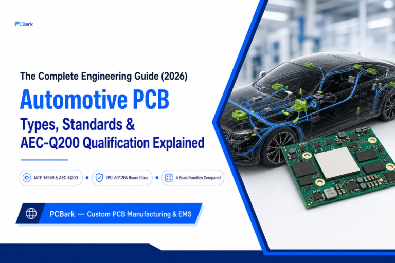
Updated July 2026 An automotive pcb is a printed circuit board built and qualified to survive a vehicles operating environment— routinely -40C to 125C or higher, constant vibration, and years of thermal cycling— and to provide the documentation trail (AEC-Q200,…
IoT PCB Design, Manufacturing, and Sourcing: What Engineers Need to Know
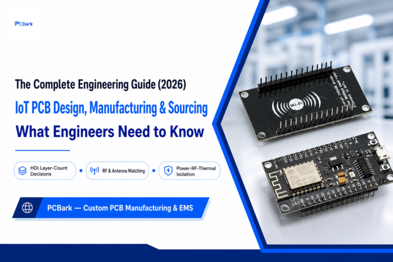
Quick Specs Typical Layer Count 2 layers (simple sensor nodes) to 6+ layers (Wi-Fi/BLE/cellular gateways) RF Trace Impedance 50 ohms, controlled impedance routing Deep-Sleep Current Target 1–5 µA HDI Trigger Point BGA pitch ≤0.5 mm or Type I microvia ≤0.15…
Everything You Need to Know About Flex PCB Assembly
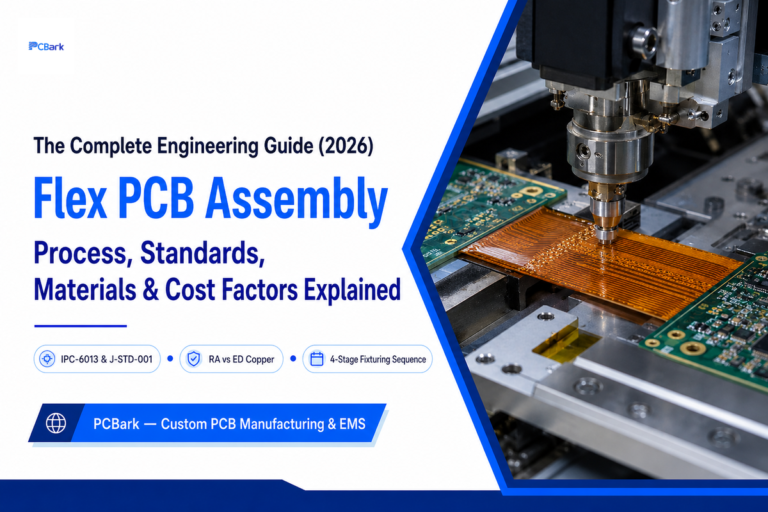
Quick Specs Substrate Polyimide (PI), 12.5-125 µm, Tg generally 250-300°C Copper foil Rolled-annealed (RA), ½-1 oz typical Reflow peak Sub-235°C, slow ramp (≤2°C/sec) Governing standards IPC-2223 (design), IPC-6013 (board qualification), J-STD-001 (soldering), IPC-A-610 (assembly acceptance) Inspection stack AOI, X-ray, flying…
Rigid-Flex PCB Manufacturing: From Materials to IPC Qualification
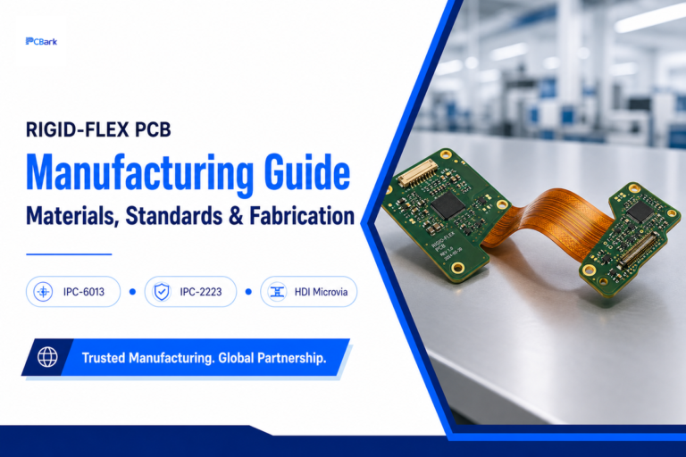
A Rigid-Flex PCB Manufacturer is a fabricator that builds boards combining rigid FR-4 sections with flexible polyimide circuits in one continuous structure, qualified under IPC-6013E and designed to IPC-2223E. The quick reference below covers the core specs; the sections that…
The Complete Guide to Flexible PCB Manufacturing (FPC)
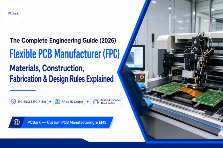
Opting for a flexible pcb manufacturer is understanding the ins and outs of a fabrication process that’s completely unlike rigid-board fabrication. This one-of-a-kind process bends, requires the copper to be bend-resistant without cracking, and the governing standards are a far…
High Frequency, RF & Microwave PCB: The Complete Engineering Guide
![High Frequency PCB Guide: RF & Microwave Design [2026]](https://pcbark.com/wp-content/uploads/2026/07/rf-microwave-pcb-guide-featured-1-768x512.png)
Quick Specs RF band ~100 MHz – 3 GHz Microwave band ~3 GHz – 30 GHz Millimeter-wave band ~30 GHz – 300 GHz (production PCBs commonly to 77–81 GHz) Typical Dk range 2.1 (pure PTFE) – 4.8 (FR-4) Standard impedance…
The Complete Guide to Gold Finger PCB Design, Plating & Edge Connector Standards
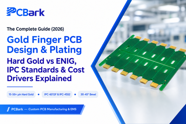
Updated July 2026 A gold finger PCB is a printed circuit board with hard-gold-plated contact pads along one edge that slide into a card-edge socket, carrying signals between boards. This guide covers the material science, plating standards, and design rules…
Rogers PCB and RF Substrate Materials: A Complete Engineering Guide
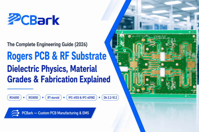
Quick Specs Common material families Ceramic-filled hydrocarbon (RO4000), ceramic-filled PTFE (RO3000), pure PTFE (RT/duroid) Dielectric constant (Dk) range 2.2 – 10.2 depending on grade Cost vs. standard FR4 Roughly 3–8× per panel, grade-dependent Governing base-material standard IPC-4103 (vs. IPC-4101 for…
Heavy Copper PCB: Materials, Manufacturing, Design Rules & Standards
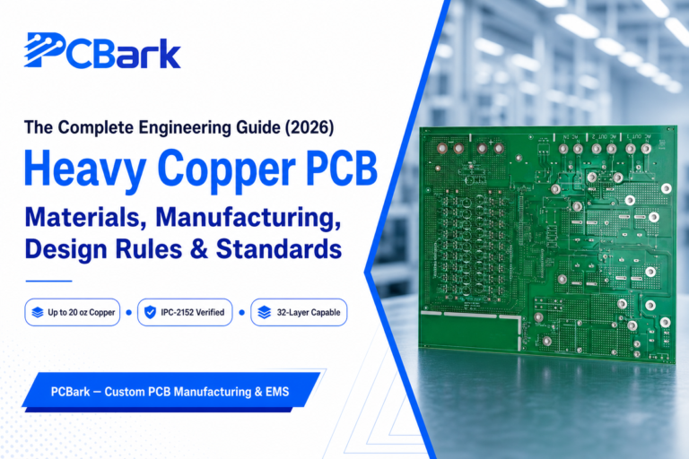
heavy copper pcb. A heavy copper pcb is a printed circuit board constructed using copper weights far heavier than the 1-2 oz found in standard boards. The material, process, and standards selection process makes the difference between a board that…
How Ceramic PCB Substrates Actually Work: A Materials-to-Reliability Guide
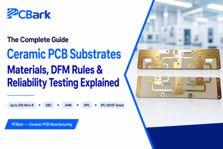
Quick Specs Substrate materials Al₂O₃ (alumina), AlN, Si₃N₄, BeO Thermal conductivity (bulk, room temp) 24–320 W/m·K, material-dependent Operating temperature −55°C to 350°C+ (tier-dependent) Dielectric constant ~6.8–10 (material-dependent) Metallization routes Thick film, thin film, DPC, DBC, AMB, LTCC/HTCC A ceramic PCB…