Get in touch with PCBark Company

ISO 9001 & IATF Certified
Automotive PCB
Automotive PCB Manufacturer, IATF 16949 / AEC-Q Boards for EV, ADAS & Powertrain Electronics
One automotive PCB partner for every board in the vehicle, high-Tg rigid, aluminum metal-core, heavy copper, HDI, flex, rigid-flex, RF and ceramic, built to IATF 16949, AEC-Q and IPC-6012DA requirements and carried from DFM review through fabrication, SMT assembly and functional test on one line.
PCBark Automotive PCB — At a Glance
- Rigid · MCPCB · Heavy Copper · HDI · Flex/Rigid-Flex · RF · Ceramic
Board technologies for every subsystem
L1::CORE_LAYOUT
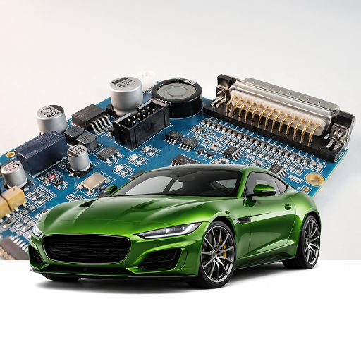
L2::HDI_ASSEMBLY
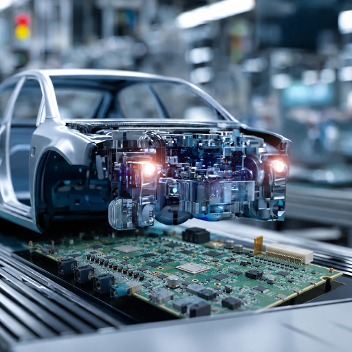
[ SYSTEM STANDBY ]
16+ years · 500,000 m²/yr
Turnkey EMS: DFM → fab → assembly → test
AEC-Q100 Grade 0–3
−40 °C to +150 °C operating zones
0.5 – 20 oz copper · 1–40 layers
Signal to high-current power
IPC-6012 Class 2/3 · IPC-6012DA
10–20 year service life
Built to IATF 16949 & AEC-Q requirements
Designed to outlast the vehicle
Automotive PCB Types by Vehicle System: the Subsystem-to-Technology Crosswalk
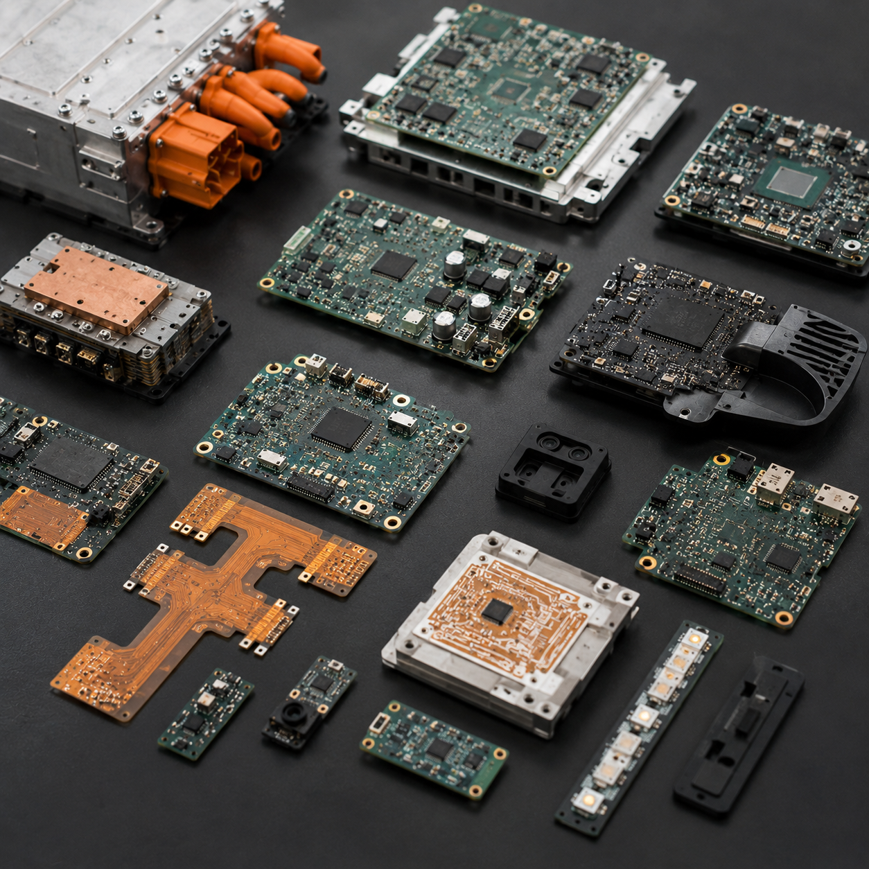
No single board type serves a whole vehicle. A power inverter, an ADAS radar antenna and a cabin sensor have nothing in common electrically or thermally, so a credible automotive PCB program mixes substrates by subsystem, power sections on ceramic or heavy copper, control and infotainment on FR-4, sensor interconnects on flex. Below, the crosswalk maps each major vehicle subsystem to the board technology, material and standard it actually needs, drawn from how these boards are built across the industry and matched to the technologies PCBark runs in-house.
CROSSWALK MAPPED
The Automotive PCB Subsystem-to-Technology Crosswalk — subsystem × board type × material × why
| Vehicle subsystem | Board technology | Material | Why this technology |
|---|---|---|---|
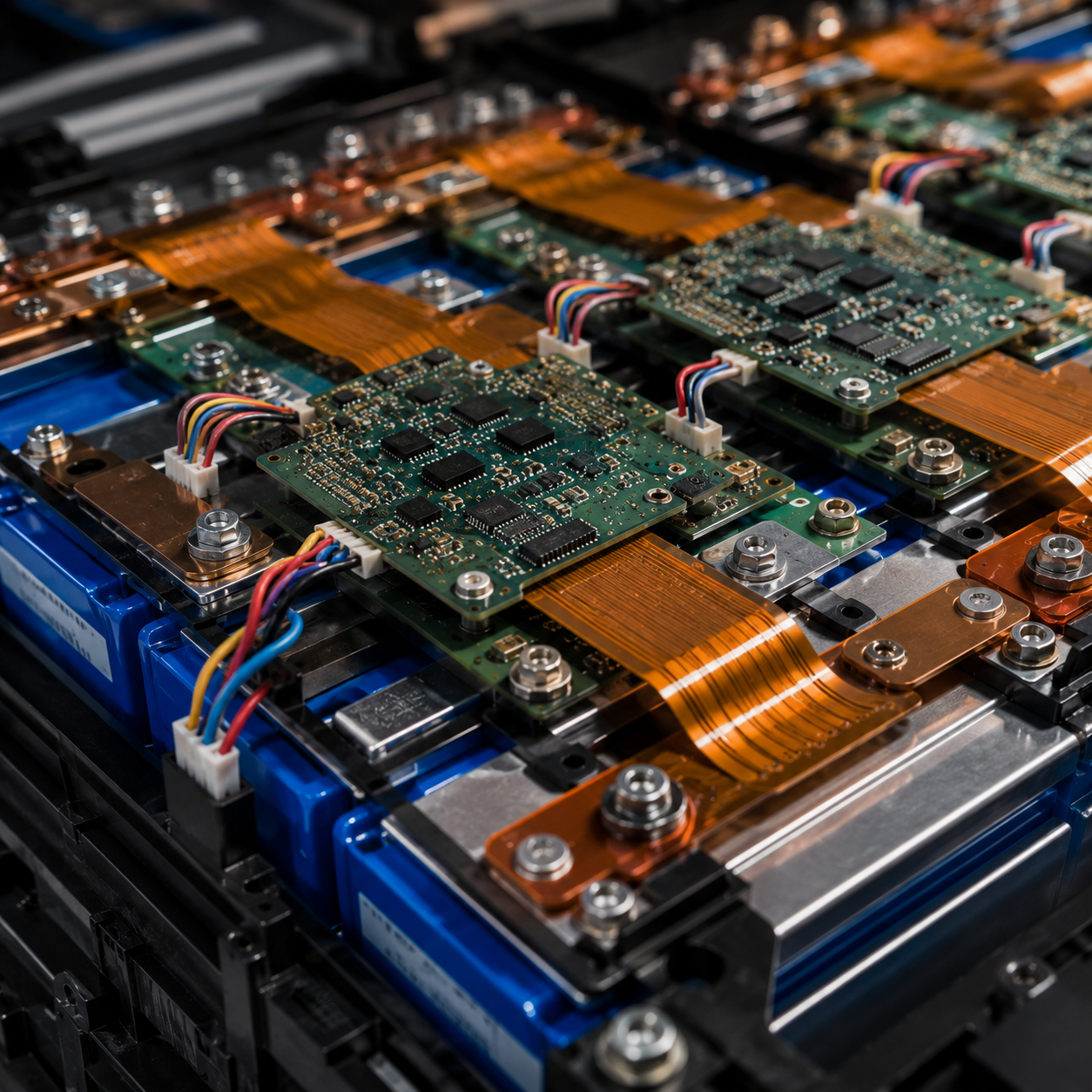
| EV battery management (BMS) | Multilayer HDI + flex interconnect | High-Tg FR-4 + polyimide flex | Dense low-noise cell sensing, HV isolation, vibration-tolerant module-to-module links |
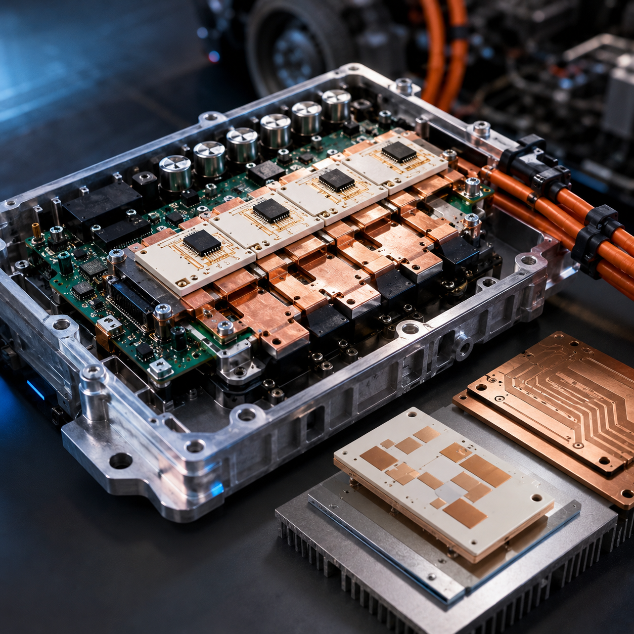
| Traction inverter / motor drive | Heavy copper & ceramic DBC | 2–20 oz copper; Al₂O₃ / AlN for SiC/GaN | High current and heat density; at the highest-power nodes the bare board is a thermal barrier, so heat moves through a direct-bonded-copper ceramic path |
| On-board charger / DC-DC / PDU | Heavy copper multilayer | High-Tg FR-4, thick copper or IMS | High-current distribution with EMI control and voltage regulation |
| LED headlamp & lighting | Aluminum metal-core (MCPCB) | Aluminum substrate, thermal dielectric | Pulls heat from high-brightness LEDs; cost-effective for lighting (not for bare-die power) |
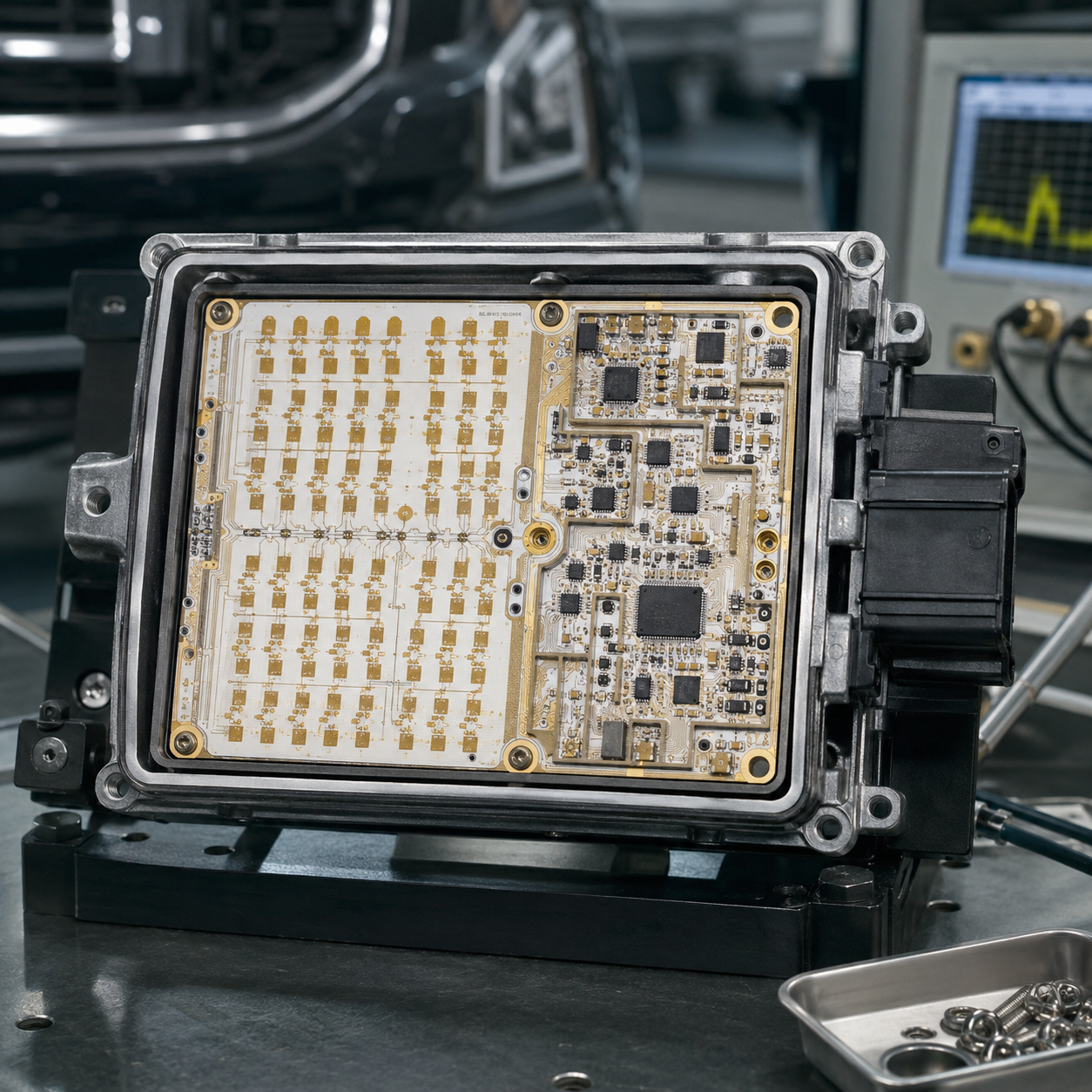
| ADAS radar (77 GHz) | RF / microwave + HDI | Ceramic-filled PTFE (Rogers RO3003 class) | Low, stable dielectric loss for millimetre-wave signal integrity |
| LiDAR, camera, sensor fusion | HDI | High-Tg FR-4, low-loss hybrid | High-speed routing and miniaturization with controlled impedance |
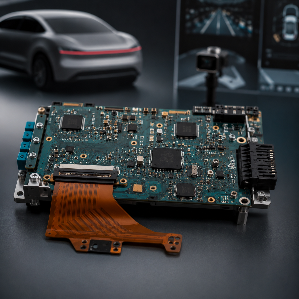
| Domain / zonal controller (VCU) | Multilayer HDI + rigid-flex | High-Tg FR-4 + polyimide | Centralized compute, dense interconnect, automotive-Ethernet differential pairs |
| Infotainment, displays, body & comfort sensors | Flex & rigid-flex | Polyimide flex | Compact interior packaging; flex cuts vehicle wiring weight 60–75% and survives >100,000 bend cycles |
Under-Hood Temperature Zones & PCB Material Selection (FR-4 Tg, Polyimide, Ceramic)
There isn’t just one “automotive Tg.” The ideal material depends on the specific location of the board within the vehicle; a blanket “automotive means Tg 170 minimum” overspecifies what’s needed for cabin electronics while underservicing an engine-bay module. Below, the chart relates the AEC-Q100 ambient temperature operating grades to the five thermal-cycling stress levels, aligned with the road-vehicle environmental tests of ISO 16750 commonly used as benchmarks by the industry to define zones in a vehicle and identifies the appropriate material laminate for each zone.
The Under-Hood Temperature-Zone Material Grade Chart
| Vehicle Zone | AEC-Q100 Grade / TCT Level | Temperature Range | Suitable Laminate |
|---|---|---|---|
| Protected passenger compartment | Grade 3 / TCT A | −40 °C to +85 °C | Standard FR-4 (Tg 130–140 °C) |
| Cabin / body electronics | Grade 2 | −40 °C to +105 °C | Mid-Tg FR-4 (Tg 150–160 °C) |
| Chassis, body, ADAS radar, infotainment | Grade 1 / TCT B | −40 °C to +125 °C | High-Tg FR-4 (Tg 170–180 °C) |
| Above engine | Grade 0 / TCT C | −40 °C to +145 °C | High-Tg FR-4 / polyimide |
| Transmission / within engine | Grade 0 / TCT D–E | −40 °C to +165 °C | Polyimide (Tg 250 °C+) or ceramic |
Our engineers keep the maximum continuous temperature on any board material about 20 °C below the laminate’s Tg. Standard FR-4 (Tg approx. 130 °C) safely operates up to around 110 °C, while a high-Tg laminate (Tg approx. 170 °C) can withstand operation up to around 150 °C.
But Tg alone doesn’t define all there’s to know about a laminate: its decomposition temperature, the point at which the resin has lost 5 percent of its mass is equally important, given that a lead-free reflow cycle hits between 240 and 260 °C. A laminate with a low Td could even break down during manufacturing and form the seed for conductive anodic filament leakage long before the vehicle ever hit the road. IPC-4101 links these metrics in its /26 and /126 slash sheets, which define the Tg 170 °C, Td 340 °C class of materials most often used in automotive and IPC Class 3 applications.
“The most expensive material on the shelf is rarely the right one. We had a customer spec alumina ceramic because they were nervous about a 1 W LED array, we moved them to high-Tg FR-4 with thermal vias, kept the junction temperature in spec, and saved them roughly 65% on unit cost. High-Tg FR-4 covers about 90% of automotive designs under 5 W/cm². We reserve ceramic for the power nodes that genuinely need it.”
A word of caution that runs against the usual “more thermal capability is always better” instinct: ceramic is rigid but brittle, so in a high-vibration zone FR-4 actually absorbs mechanical shock better, and swapping a substrate is never a drop-in fix, copper balance, edge clearance, mounting torque and the solder profile all have to be reworked.
Selecting the laminate is a trade-off between heat transfer, vibration tolerance, manufacturability and cost, not a single-number race. And because PCBark stocks and processes all five zone-matched material classes in-house, standard and high-Tg FR-4, polyimide, and Al₂O₃/AlN ceramic, across 500,000 m²/yr of capacity, the recommendation is driven by your operating zone, not by whichever laminate a single production line happens to run. Unlike a shop tied to one material, we’ll honestly tell you when standard FR-4 is the right call and save you the ceramic premium.
Material choice shapes the rest of the automotive circuit design too. On a multi-layer board that runs high-speed digital next to a radio-frequency stage, heat dissipation and signal isolation pull in opposite directions — the board has to dissipate heat while stopping radio frequency interference from coupling into sensitive nets. Class 3 boards earn their high-reliability rating only when laminate, copper and stackup are chosen together; standard FR4 handles the low-power digital, and the hard part is the boundary — a design-process call, not a material one.
PCBark Automotive PCB Capabilities, Full Specification Table
Most automotive PCB pages tell you they build “high-quality, reliable” boards. Below is the specification our own engineers quote against, spanning the board technologies an automotive program actually draws on. Match your requirement to a row before you send an RFQ and you’ll skip a round of back-and-forth.
PCBark Automotive PCB Capability Across Board Technologies
| Parameter | PCBark Automotive Capability |
|---|---|
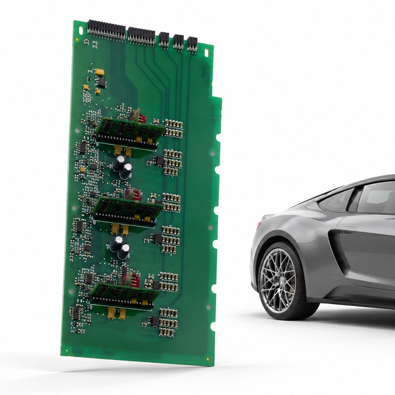
| Board technologies | Rigid high-Tg, aluminum metal-core (MCPCB), heavy copper, HDI / any-layer, flex, rigid-flex, RF / Rogers, ceramic (Al₂O₃ / AlN) |
| Layer count | 1–40 layers (rigid); 1+N+1 to any-layer HDI |
| Base material / Tg | Standard (Tg 135 °C) → mid-Tg (150 °C) → high-Tg (170–180 °C); polyimide (Tg 250 °C+); RO3003-class PTFE for radar; Al₂O₃ / AlN ceramic |
| Copper weight | 0.5 oz to 20 oz (heavy copper) |
| Min. trace / spacing | 3 mil / 3 mil standard; 2 mil / 2 mil (0.05 / 0.05 mm) HDI |
| Min. mechanical / laser via | 0.15 mm mechanical; 0.10 mm (4 mil) laser microvia |
| Hole-position accuracy (Class 3) | ±100 µm; hole-wall separation ≤ 40% of dielectric; 75% barrel fill; internal annular ring ≥ 1 mil |
| Parameter | PCBark Automotive Capability |
|---|---|
| Impedance control | ±10% standard, ±5% available (TDR-verified) |
| Surface finish | Lead-free HASL, ENIG, ENEPIG, immersion silver, OSP, hard gold |
| Operating-temperature grade | AEC-Q100 Grade 0–3 (−40 °C to +150 °C); on-engine builds to +165 °C with appropriate laminate |
| Fabrication standard | IPC-6012 Class 2/3 + IPC-6012DA automotive addendum; IPC-6013 (flex / rigid-flex) |
| Assembly standard | IPC-A-610 Class 2/3; IPC J-STD-001; built to IATF 16949 / AEC-Q automotive requirements |
| Test & verification | AOI, flying probe, in-circuit test, BGA X-ray, TDR, thermal cycling, hi-pot, ionic cleanliness |
Capabilities
×
Automotive PCB Standards & Quality: IATF 16949, AEC-Q, IPC-6012DA & ISO 26262
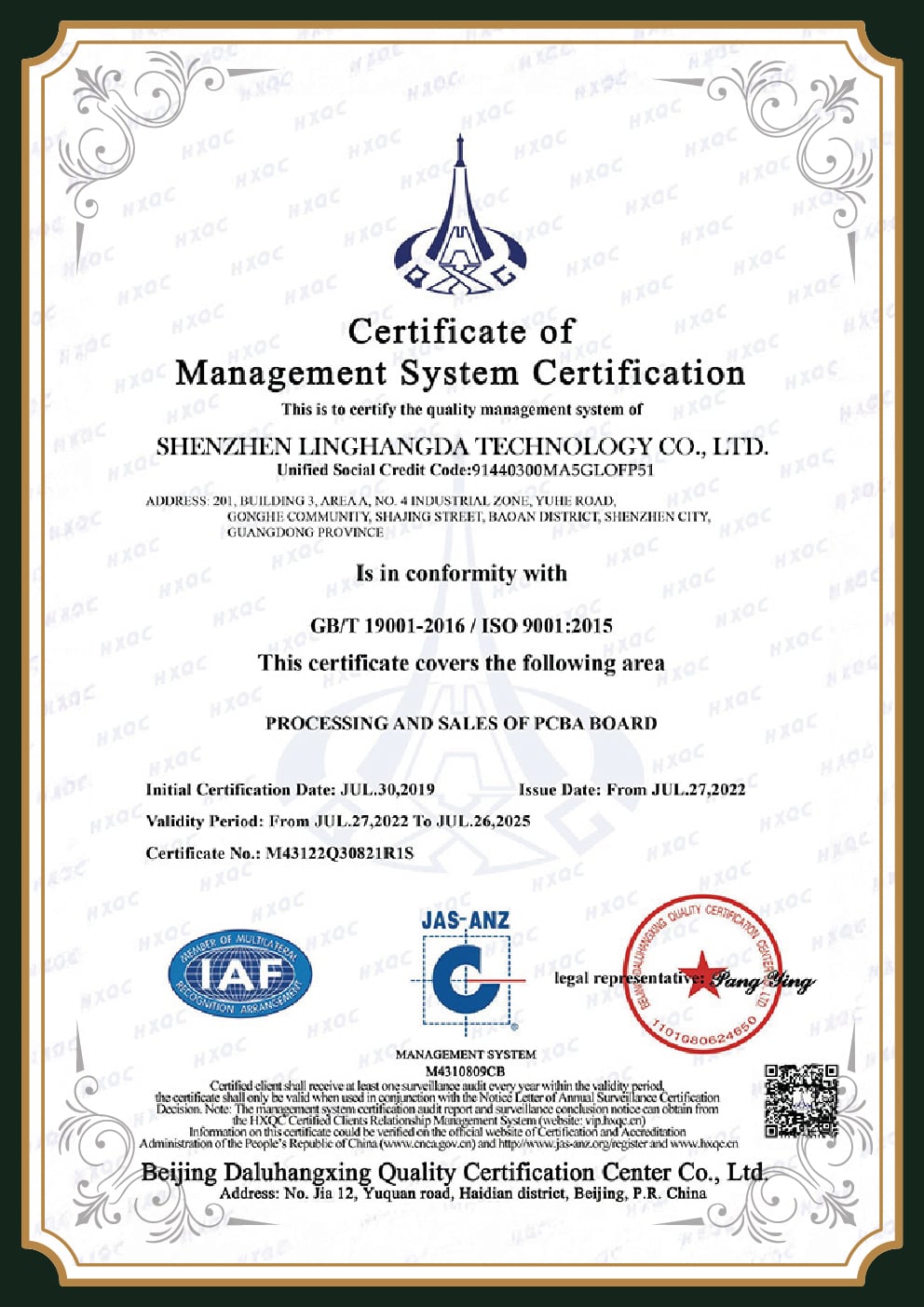
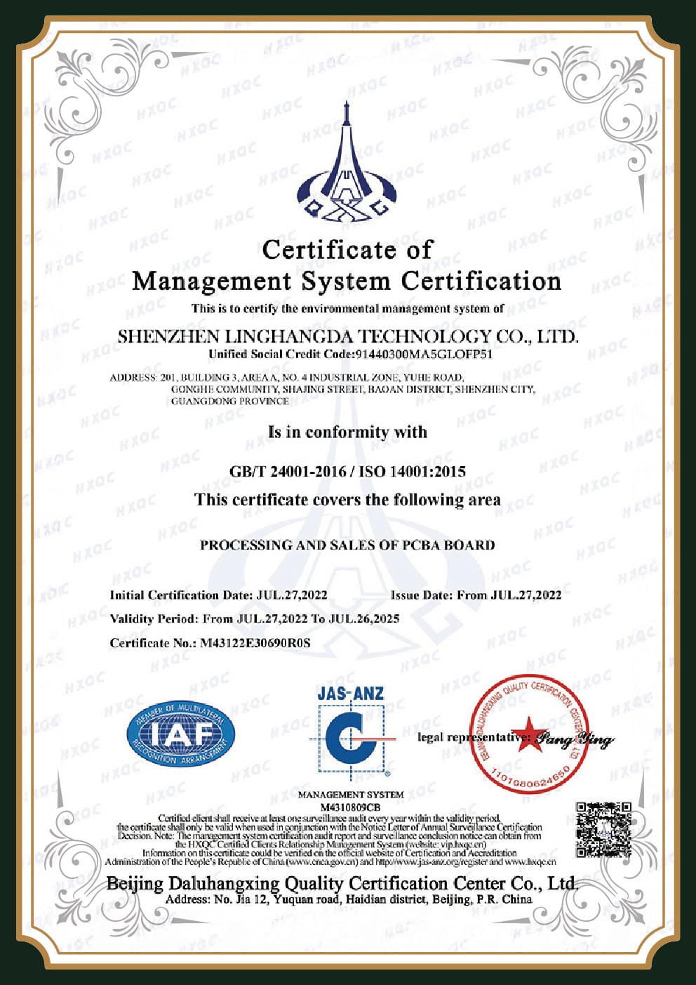
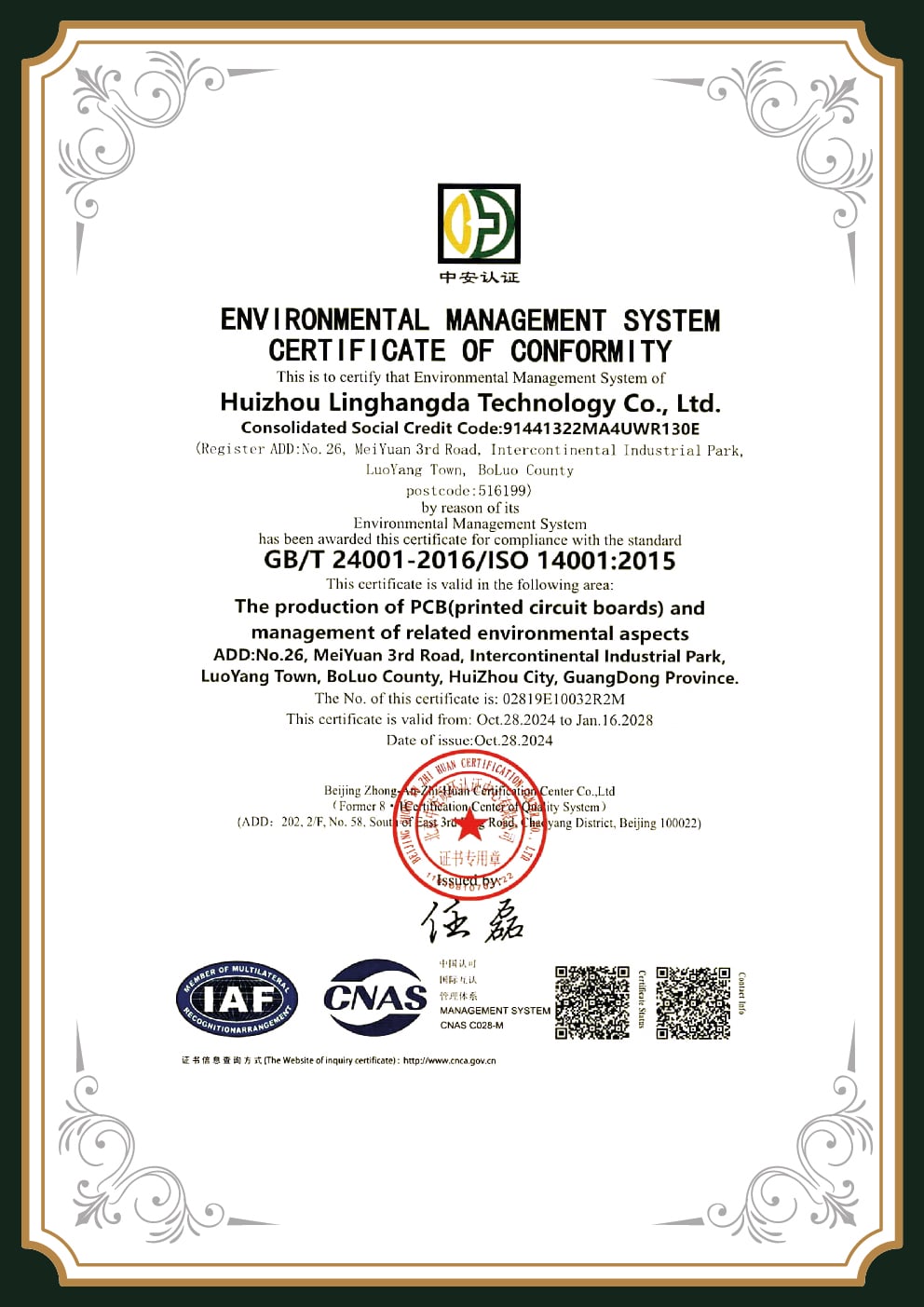
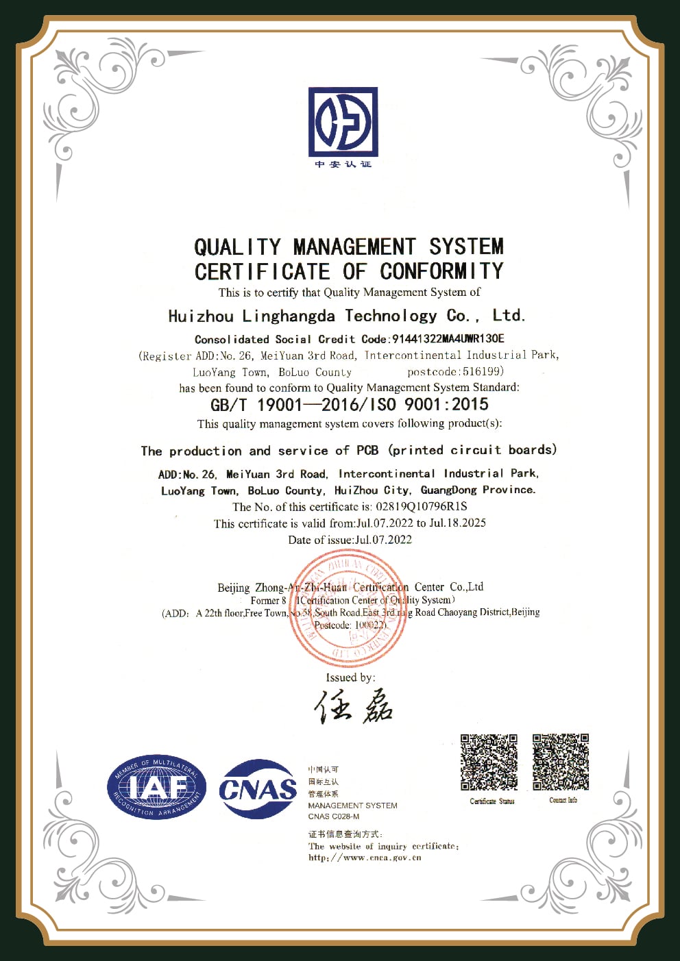
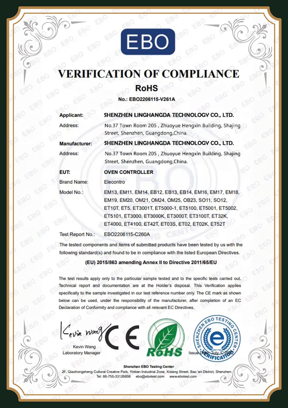
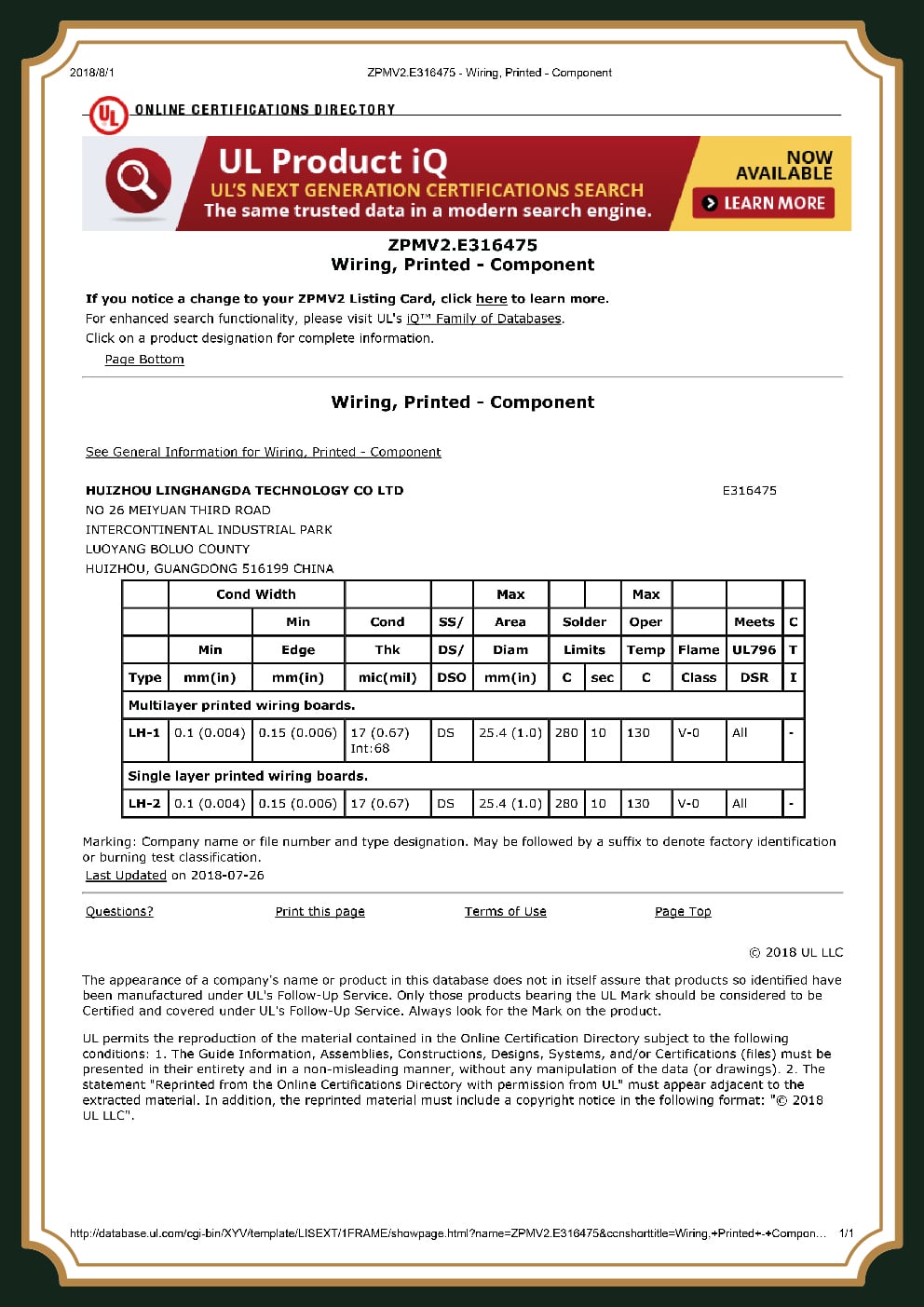
In automotive electronics, a stated certification isn’t proof, sophisticated buyers have learned that a supplier can print “IPC-6012 Class 3” on a drawing and have done none of the qualification, conformance or acceptance testing to back it, which is exactly how plating cracks and field recalls happen. A facility tour and lunch isn’t a quality system. What closes the trust gap is the test evidence behind the standard, so here’s the reliability stack every PCBark automotive board is built and verified against.
The Automotive Reliability Test Stack
| Test | Standard / method | Condition | What it proves |
|---|---|---|---|
| Thermal cycling | JEDEC JESD22-A104 / IEC 60068-2-14 | −40 °C to +125–150 °C, 500–1500 cycles | Solder joints & plated barrels survive expansion / contraction |
| Thermal shock | Molten-solder immersion | 260 °C or 288 °C, 10 s, ×3 | No lamination, blistering or copper crack at reflow extremes |
| Temperature-humidity bias | JEDEC JESD22-A101 | 85 °C / 85% RH, 1000 h | No conductive-anodic-filament (CAF) growth between vias / traces |
| Biased HAST | JEDEC JESD22-A110 | 130 °C / 85% RH, 96 h | Accelerated humidity-bias insulation integrity |
| Bare-board acceptance | IPC-6012DA addendum | Bow & twist ≤ 0.75%; wicking ≤ 60 µm; cleanliness ≤ 0.75 µg/cm² | Tighter-than-general automotive workmanship after 2× 260 °C precondition |
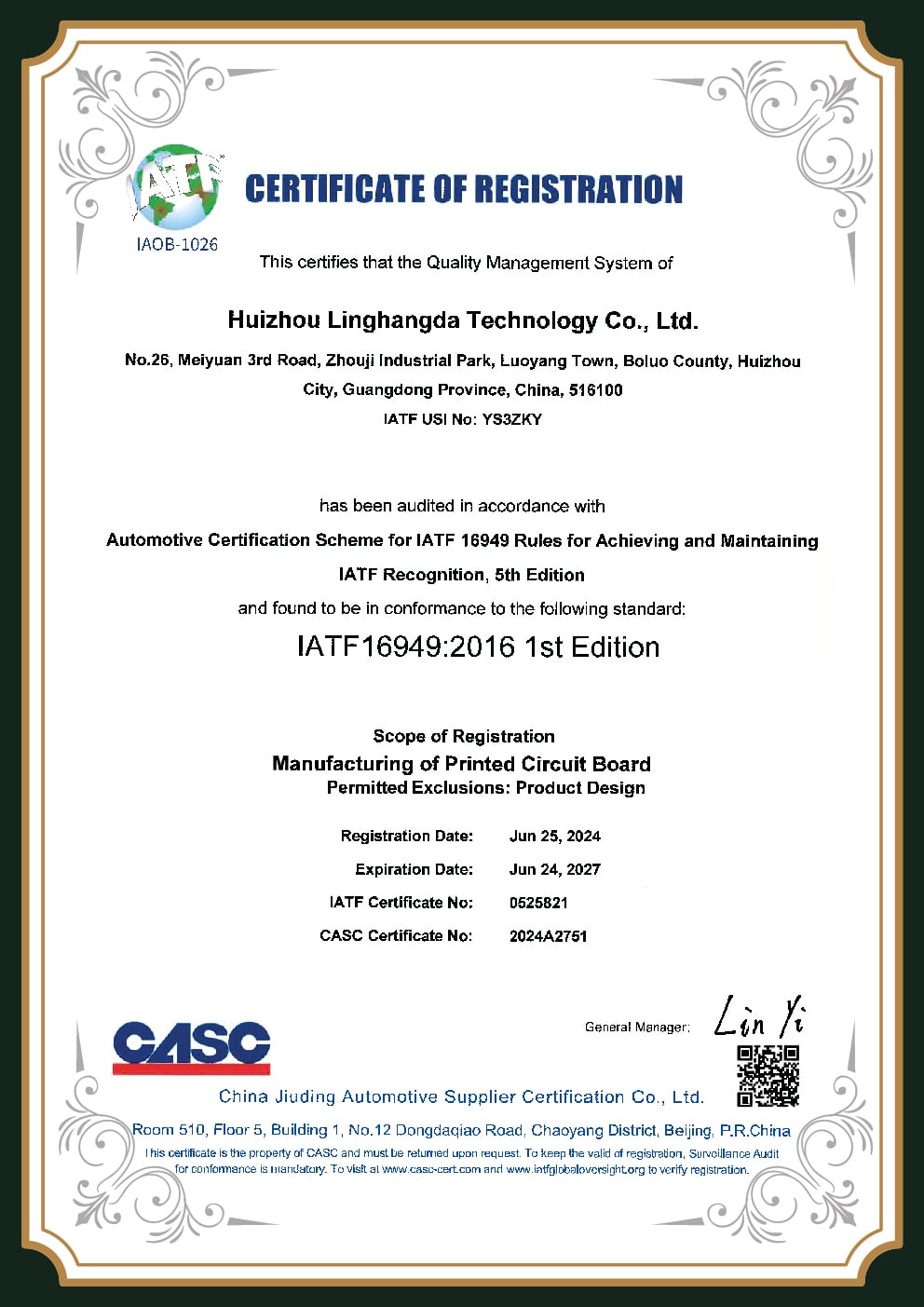
Quality sits above the board itself. IATF 16949 is the automotive QMS that builds on ISO 9001 and adds defect-prevention discipline, the APQP / PPAP / FMEA documentation package, and full lot traceability so a nonconforming board is rendered unusable rather than reaching the road. It cascades down the supply chain, most OEMs mandate it for Tier-1 suppliers, with more than 65,000 certified facilities worldwide, but, honestly, it is contractually driven by your direct customer, and the IATF rules themselves only require customers to develop their sub-tier suppliers’ systems.
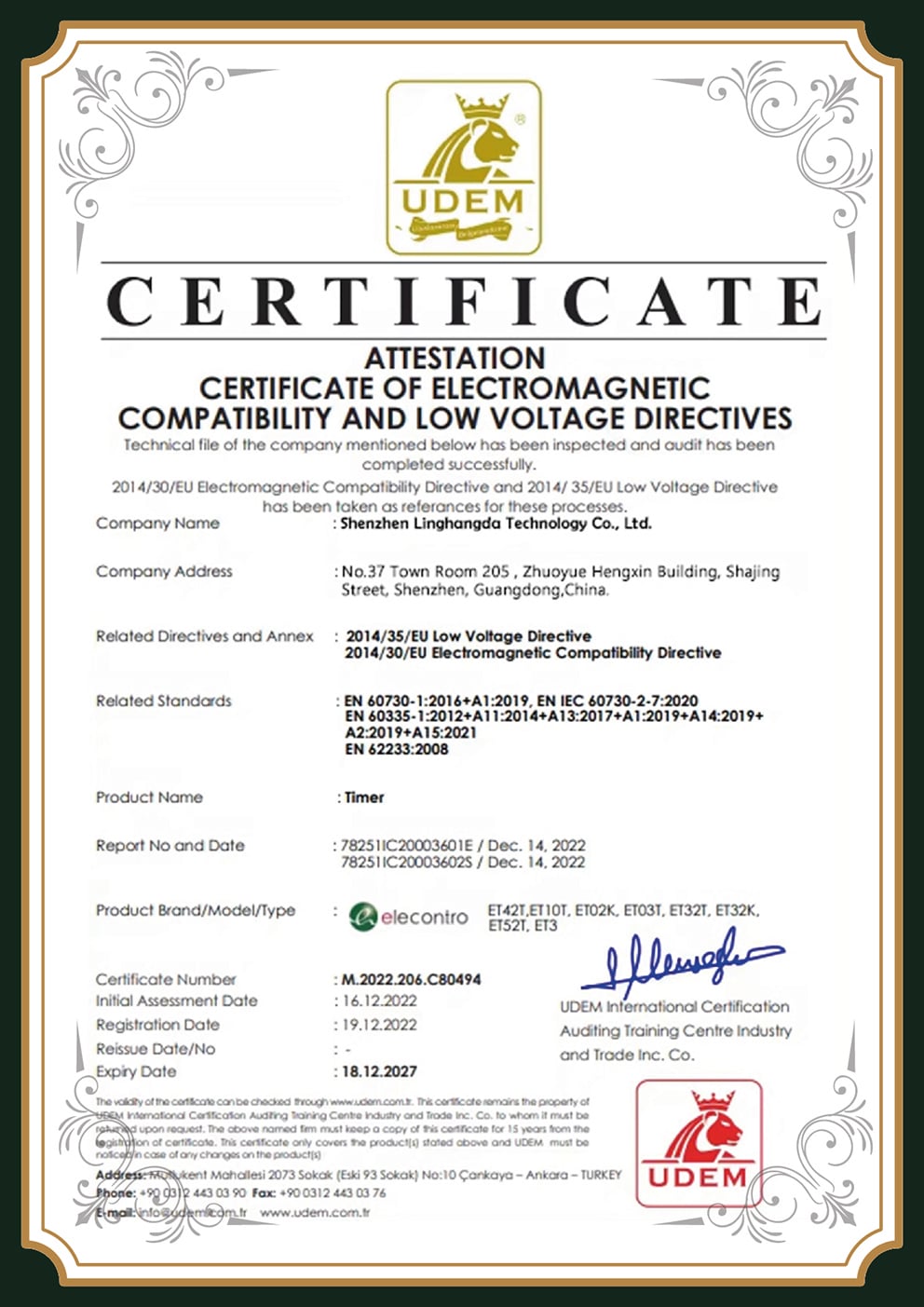
PCBark manufactures to IATF 16949, IPC-6012 Class 3 and AEC-Q automotive requirements under advanced international quality-management systems and IPC workmanship standards; where your program requires a held certificate at a specific tier, we confirm current certification status before you commit.
Higher IPC class isn’t, necessarily, the better decision – it is aligned to subsystem safety level, not maximized for its own purpose. Under ISO 26262, the IPC-6012 automotive addendum maps motor-management, HV, headlight and safety PCBs to Class 3, and body electronics, LV ECUs and rear lamps legitimately Class 2 – assigning Class 3 across the board adds expense with no ASIL reasoning. The component side is governed by the AEC-Q series: AEC-Q100 for ICs, AEC-Q101 for discretes, AEC-Q102 for optoelectronic components, AEC-Q200 for passives.
IATF 16949
Automotive QMS (built to)
IPC-6012 Class 2/3
Rigid board qualification
IPC-6012DA
Automotive addendum
AEC-Q aligned
Q100 / Q101 / Q200
ISO 26262
ASIL-mapped IPC class
Automotive PCB Assembly (PCBA): SMT, Through-Hole, Conformal Coating & Turnkey
01
By far the worst pain in the automotive PCBA buying experience isn’t price or lead-time – it’s what occurs when an assembly returns defective. Actual purchasers characterize cold-solder joints, unpopulated or 90°-rotated parts, and vendors who admit the defect and then advise the customer to find a local repair shop. For a vehicle board, that isn’t an annoyance; it’s a field-failure and recall risk. PCBark provides it with accountability built-in to the process, not generic “zero-defect” language that isn’t backed by defined process inputs.
02
Every automotive assembly follows the same disciplined approach: proactive design-for-manufacturing (DFM) review of your automotive PCB design prior to tooling, then SMT and through-hole placement, automated optical inspection, BGA X-ray, flying-probe or in-circuit electrical test, conformal coating for moisture and chemical resistance, and box-build integration where necessary – with lot and material traceability recorded at each stage against test reports from an ISO/IEC 17025-accredited lab. 100% continuity testing is the minimum, not a premium. Since fabrication and assembly are performed in a single location, a defect can be followed up to its process step instead of falling into the gap between two suppliers.
03
A fair caveat on scope: not all PCBA’s delivered to vehicle need the full automotive-certification path. Some initiatives need that tighter traceability & open process flow communication outside of typical PCBA. Inform us of the real program compliance expectations up front & we scope the assembly in line – not under-building an adjunct board or over-charging a body-electronics one.
Automotive PCB Engineering & Material Selectors
Automotive PCB Zone & Material Selector
Pick where the board lives in the vehicle to see its AEC-Q100 temperature grade and the laminate that survives it.
Subsystem-to-PCB-Technology Selector
Choose a vehicle subsystem to see the board technology, material and qualification standard it typically needs.
Substrate Right-Sizer: FR-4 vs MCPCB vs Ceramic
Most automotive boards do not need ceramic. Answer four questions to see the substrate that fits your thermal and mechanical load — without over-paying.
Automotive PCB FAQ, Common Buyer Questions
What is a PCB in a car, and what does it do?
A PCB (printed circuit board) is the rigid or flexible board that mounts and connects the electronic components behind almost every vehicle function, engine and motor control, battery management, ADAS sensors, lighting, infotainment, and safety features such as airbags and braking. A modern vehicle contains more than 200 electronic control units, and each is built on a PCB engineered to survive the car’s full 10-to-20-year service life.
What’s the difference between an automotive PCB and a standard PCB?
An automotive PCB is qualified to survive a wider temperature range (−40 °C to as high as +150–165 °C) plus the road-vehicle environmental loads of ISO 16750 continuous vibration up to 50 g, thermal cycling, humidity and electrical load-dump transients, for 10–20 years. That usually means higher-Tg laminate, controlled coefficient of thermal expansion, IPC-6012 Class 2/3 fabrication with the IPC-6012DA automotive addendum, and AEC-Q-grade components, testing and material discipline a consumer board never receives.
Is an ECU a PCB?
Not exactly, an electronic control unit (ECU) is a complete module that contains a PCB along with its components, connectors and housing. The PCB is the board inside the ECU that carries and interconnects the microcontroller, power circuitry and sensors. A car can have 200+ ECUs, each built around one or more automotive PCBs.
Does an automotive PCB supplier need IATF 16949 certification?
It depends on your position in the supply chain. Most OEMs mandate IATF 16949 for Tier-1 suppliers, but the requirement is contractually driven by your direct customer, and a bare-board fabricator may legitimately operate under ISO 9001 plus customer-specific requirements. What matters most is verifiable qualification and acceptance test evidence and full traceability, not a logo on a homepage. Tell us your program’s tier and compliance expectations and we’ll confirm what’s required.
What are the different grades of automotive PCB?
Grades are defined by operating temperature, following the AEC-Q100 scheme: Grade 3 (−40 to +85 °C) for the protected passenger compartment, Grade 2 (−40 to +105 °C) for cabin electronics, Grade 1 (−40 to +125 °C) for body, ADAS radar and infotainment, and Grade 0 (−40 to +150 °C) for engine-compartment and on-engine modules. Its laminate Tg and IPC class are then matched to the zone.
Is automotive-grade always better, or worth the cost?
Not automatically. Automotive qualification is worth paying for when your subsystem’s real stress profile, heat, vibration, voltage, service life, demands it. Field experience shows that over-specifying grade or substrate (for example, ceramic where high-Tg FR-4 would do) wastes budget and lead time without adding reliability. High-Tg FR-4 handles roughly 90% of automotive designs under 5 W/cm²; ceramic earns its place at the high-power, high-temperature nodes. We size the board to the application.
How much does automotive PCB assembly cost?
There’s no single figure, an automotive PCBA quote is driven by board technology and material, layer count and copper weight, IPC class and qualification scope, volume, and whether you need bare board or full turnkey assembly with conformal coating. Remember that a defective board cost about 10× more after assembly than before, so the right comparison is total cost of ownership, not unit price. Send your Gerber, BOM and program requirements for a firm quotation.
![Drone PCB Design Guide: IPC Class & Manufacturing [2026]](https://pcbark.com/wp-content/uploads/2026/07/drone-pcb-design-guide-featured-150x150.png)