
Get in touch with PCBark Company

PCBark · Aerospace & Avionics Electronics
Aerospace PCB Manufacturing & Assembly
Flight hardware doesn’t fail at the spec sheet. It fails at the via barrel, the solder joint, and the laminate – long before it breaks on paper. And that means it has to be designed, built, and proven to withstand all three.
As an aerospace PCB manufacturer serving commercial aviation, UAV, and satellite programs, PCBark fabricates and assembles every board to IPC-6012 and IPC-A-610 Class 3 acceptance. That standard is backed by 16 years of experience, eight SMT lines, and the insights of 2,000+ global users. This page lays out our manufacturing capabilities, their governing standards, and an honest picture of what we do — and don’t — build.
Get a Quote

Why Aerospace PCBs Fail, and How We Build Them to Survive
Very rarely do printed circuit boards for aerospace fly because a trace wasn’t perfectly the right width. In the aerospace operating environment, boards are subjected to extreme temperature and vibration. Copper, laminate, and solder expand and contract at varying rates over thousands of thermal cycles. Those differences flex via barrels apart, delaminate layers, and fracture solder joints – the real world mechanisms that take flight hardware out of commission.
The second cause of in-application failures: brittle intermetallic fractures that develop in the solder joints. With coupled thermal and vibration stresses working together, both damage modes are amplified. In fact, that combined effect explains why stringent aerospace qualifications use rigorous testing combinations like thermal-vacuum and mechanical shock and vibration profiling instead of isolated tests.
SYSTEM SPECIFICATIONS Root cause → design response
- Via barrel cracking caused by Z-axis CTE mismatch: CTE matched high-TG laminate Filled and capped via 25m hole-wall copper
- Delamination at the resin interface: High-TG FR-4 or polyimide systems designed for thermal stability.
- Solder joint fatigue under thermal cycling: Class 3 acceptance,AOI, and X-ray inspection of all solder joints.
- RF phase drift in high frequency layers: Controlled impedance to within 5% on all Rogers and Megtron stackups.
- Service moisture and contaminants: Epoxy and polyimide conformal coating options that add durability under extreme temperatures, humidity, and salt fog.
Physics – not sales jargon – dictates whether hardware survives. As peer-reviewed reliability analysis and USPTO patent US20170303392A1 both show, ductile solder failure contributes to thermal cycle issues and brittle intermetallic cracking explains many vibration failures. Our approach to this problem is patented (US Patent US20170303392A1), which demonstrates that matching the Z-axis CTE of the laminate and conductors is the most direct way to prevent via barrels from fracturing.
Designing for a harsh-environment program?
Send your stack-up for a free DFM check →
SYSTEM & PROCESS CAPABILITIES
Aerospace PCB Capabilities, Board Types, Materials & Specs
Using the wrong board technology for your aerospace application results in wasted weight, test failures or even a complete design restart. Generally, no one aerospace product uses just one type of board – think of a rigid-flex interconnect feeding signals to sensors on the end of a mechanical arm, next to a high-density compute board for processing, and a high-frequency front end for data transmission. At PCBark, we build all these designs in-house, which means we can control the board materials, stack-up, impedance, and traceability. Our front-end PCB design review and DFM process gets each of these boards ready to be manufactured to current aerospace PCB design standards, drawing on advanced technologies across our HDI and rigid-flex lines.
Below, each row maps the common aerospace applications that PCBark supports, identifies the primary technical specification of importance, and delineates our demonstrated capability for each board type. This table doesn’t represent aspirational standards but empirically proven fabrication capabilities from our process control data sheets.
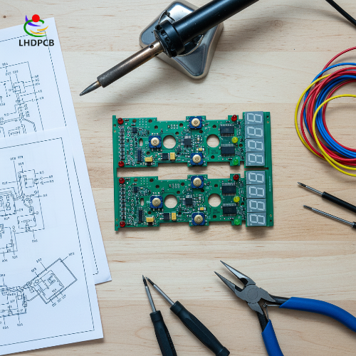
The Aerospace PCB Class-3 Capability Matrix
| Board type | Aerospace role | Layers | Key spec | Standard / finish |
|---|---|---|---|---|
| HDI PCB | Avionics processors, dense controllers | up to 32 / any-layer | laser via 0.050 mm, BGA 0.30 mm pitch | IPC-6012 Cl.3 / ENEPIG |
| Multilayer PCB | Backplanes, power & signal boards | up to 32+ | impedance ±5%, registration ±35 µm | IPC-6012 Cl.3 / ENIG |
| Rigid-Flex PCB | UAV & satellite weight-critical interconnects | up to 24 | 100,000+ dynamic bend cycles | IPC-6013 / ENEPIG |
| Flex PCB | Sensor and camera modules | up to 10+ | RA copper, 0.050 mm trace/space | polyimide / Hard Gold |
| RF / Microwave PCB | Radar, comms, telemetry front ends | mixed hybrid | impedance ±5% on Rogers / Megtron | IPC-6012 Cl.3 / Imm. Silver |
| Metal-core PCB | High-power drivers, LED & lighting | 1–4 | copper to 6 oz, heat-spread base | IPC-6012 / OSP |
Material selection is where aerospace boards earn their reliability. Our laminate stacks run from high-Tg FR-4 to polyimide for flex, and for high-speed and high-frequency work we stock Rogers, Isola, and Panasonic Megtron systems, with CTE-managed power and ground planes in the spirit of USPTO-documented low-CTE plane construction.
Decision Matrix, which board for which aerospace system
| If your system is… | Priority | Recommended board | Why |
|---|---|---|---|
| UAV / drone flight controller | weight + density | Rigid-Flex + HDI | removes connectors, cuts mass |
| Satellite / NewSpace payload | 15-yr life, low mass | Rigid-Flex, polyimide | bend-tolerant, thermal-stable |
| Radar / comms front end | signal integrity | RF multilayer (Rogers) | ±5% impedance control |
| Avionics compute module | I/O density | Any-layer HDI | 0.050 mm laser vias, fine-pitch BGA |
| Power / actuator board | thermal dissipation | Metal-core or heavy-copper | 6 oz copper, heat spread |
COMPLIANCE & CAPABILITIES
IPC Class 3, ITAR & AS9100, What Aerospace Buyers Actually Need
Buyers routinely overpay for a U.S. ITAR shop they don’t actually need, or get rejected by one they do, because nobody drew the line clearly. A defense registration, ITAR or AS9100, usually isn’t required for civil avionics, UAVs, drones, or commercial and NewSpace work, where what matters is IPC Class 3 acceptance and material traceability rather than military status.
So here’s the line PCBark draws, stated plainly rather than buried in a footnote:
What we hold:
ISO 9001, IATF 16949, ISO 14001, UL, RoHS, and REACH, with builds accepted to IPC-6012 and IPC-A-610 Class 3.
What we don’t hold:
U.S. ITAR registration and AS9100 certification, and we don’t take ITAR-controlled U.S. defense work.
Where we fit:
commercial and civil aerospace, avionics R&D, UAV and drone electronics, satellite and NewSpace, and global export programs.
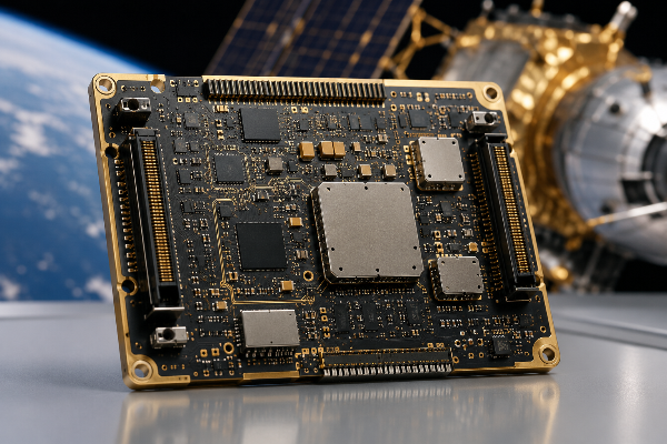
We make commercial aerospace PCBs, plain and simple — not a military aerospace PCB manufacturer in the ITAR-registered sense, because those serve different purposes. MIL-PRF-31032 and AS9100 add qualification and audit layers used across military and aerospace and broader aerospace and defense programs, whereas IPC-6012 Class 3 specifically describes what defines a physically sound PCB and covers all aspects, down to not having micro-voids. That is the honest trade-off, and we will not claim ITAR or AS9100 credentials we do not hold.
“We tell aerospace buyers the same thing every time: if your program is ITAR-controlled, use a registered U.S. fab, full stop. If it is commercial aviation, a drone, or a NewSpace payload, what protects you is Class 3 acceptance and a traceable material genealogy, and that is exactly what we document on every board.”
— PCBark Aerospace Engineering Team
Not sure which standard your program actually requires?
Ask our aerospace team →
SPECIFICATION BENCHMARK
Aerospace-Grade vs Standard Commercial PCB, The Reliability Difference
Most commercial circuit boards allow a 3-5 percent defect rate. For PCBs that will be in the air, acceptance levels need to be nearly 100 percent. IPC-6012 Class 3 specifies requirements to bridge that gap between the normal world and the airspace, and that specification is more about measuring in micrometers than just calling a product “high reliability.”
| Attribute | Commercial (IPC Class 2) | Aerospace (IPC Class 3) | PCBark build |
|---|---|---|---|
| Copper voids in plated holes | 1 void allowed per 5% of holes | zero voids | zero, X-ray verified |
| Min. hole-wall copper | 20 µm (0.8 mil) | 25 µm (1.0 mil) | 25–35 µm |
| Annular ring | breakout tolerated | defined positive ring, all layers | defined positive ring |
| Min. dielectric | — | ≥90 µm / 3.54 mil | ≥90 µm |
| Impedance tolerance | ±10% | tightened | ±5% |
| Electrical test | sampling common | 100% test expected | 100% E-test + flying probe |
We don’t invent those numbers for our Class 3 parts – they’re derived directly from the IPC-6012 publication standard, supported by USPTO patent US8250751B2 for via-reliability in filled vias. We enforce the right-hand column specs in our built PCBs on each and every aerospace order.
APPLICATION ENGINEERING
Built for Avionics, UAV/Drones, Satellites & NewSpace
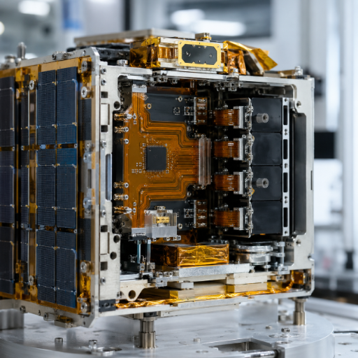
If your sole offering is rigid FR-4 then by the time first article is due on that rigid-flex or RF job, the effective scope of the bill of materials has stealthily been trimmed, and the cost of that failure lands on your program rather than the supplier’s. Avionics PCB, high reliability PCB, RF PCB – are there three distinct applications? They should be well-covered under the capability menu of a credible aerospace PCB manufacturer. Our boards operate in navigation and flight display, radar front-ends, communications transponders, weight sensitive internal cabling for satellites and drones, and on the flight-control computer.
 Avionics
01 / SECTOR
Avionics
Flight-control and display boards on any-layer HDI, I/O density without sacrificing Class 3 reliability.
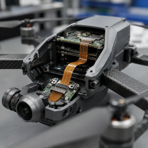 UAV & Drones
02 / SECTOR
UAV & Drones
Rigid-flex cuts connectors and mass; 100,000+ bend cycles survive airframe vibration.
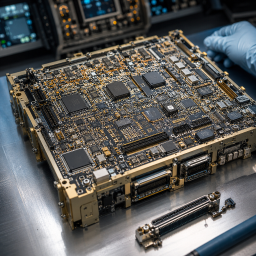 Satellite / NewSpace
03 / SECTOR
Satellite / NewSpace
Polyimide rigid-flex for low weight and the 15-year service life these payloads demand.
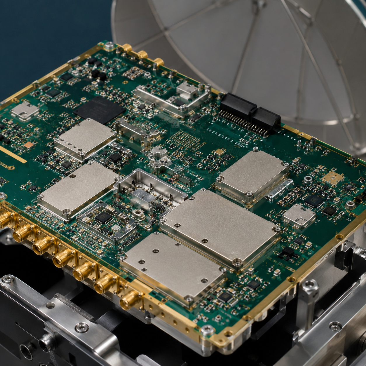 Radar & Comms
04 / SECTOR
Radar & Comms
RF multilayer on Rogers and Megtron with ±5% impedance for signal integrity.
INSPECTION & TRACEABILITY
Quality, Testing & Traceability
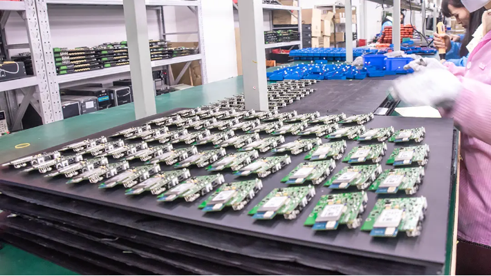
What you read in print may hide a complete void in terms of real quality systems and modern manufacturing technology. Before their purchase orders bloom into problems after they receive parts from a fly-by-night job shop, the intelligent move is for procurement departments to insist on demonstrable production reality as opposed to mere promises. Showing the test stack would prove its point far more than making an unsubstantiated claim about the “highest reliability available”. Every PCB that leaves our facility under our aerospace tab first goes through a disciplined and extensive inspection process.
Validation Process
-
01
AOI and X-ray for solder joints and internal structure, the latter with the ability to check BGA cavity and void dimensions for proper fills.
-
02
Flying probe and ICT for 100% electrical validation versus lot-level sampling of test circuits.
-
03
Burn-in and functional validation with end-use operation under stresses relevant to end application on the full board assemblies.
-
04
Per-board traceability links material lot, process parameters, and test data from copper foil to final finish.
The essence of aerospace quality systems is such traceability of material, components, process history, and test, with established methods like First Article Inspection used for material genealogy and in-process validation. Underpinning our own processes are ISO 9001, supported by IATF 16949, which provides an auditable basis in the commercial world equivalent to a number of aerospace quality assurance and control systems, including the requirements of IPC-A-610 and J-STD-001 for inspection.
Compliance Standards
- ISO 9001 Quality management
- IATF 16949 Automotive-grade QMS
- ISO 14001 Environmental
- UL Listed
- RoHS Compliant
- REACH Compliant
- IPC Class 3 Build acceptance
DRAG / SWIPE TO VIEW ALL
PROCUREMENT & SOURCING
Procurement Guide, Lead Times, Sourcing & Pricing
Procurement teams make the same mistake again and again: a misleading low headline quote includes tooling, test and shipping fees that reappear as the landed cost with tax duties included. Waiving the electrical test to bring down the per-unit cost is even worse: a faulty bare board inside your assembled unit renders the costly rework cost equal to the full assembled cost, not the bare board. Overall costs of ownership consider the defect rate and vendor-management costs a lot more than the per-line item price.
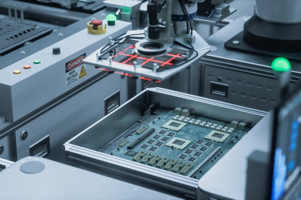 CLICK / HOVER TO READ SOURCING DATA →
SOURCING DETAILS
Components arrive in the shop from one of the reputable suppliers: Arrow, DigiKey and Avnet are all “authorized”; each comes with traceable lots; and all builds are turned “full turn key,” “partial turnkey” or “consignment” – depending on how a team shops. Lead time from concept to production runs somewhere between 1 to 15 days, depending on the specifications. Unlike suppliers that hide tooling and test behind a murky lump-sum price, PCBark returns a transparent, itemized quote that spells every line out, backed by eight SMT lines and per-board traceability aligned to ISO 9001. Skipping electrical test to shave that price is the costliest move of all, since a defective bare board inside your assembly forfeits the whole assembled value — so email your Gerber and BOM for an exact, itemized number.
What actually drives your aerospace PCB quote
Rather than the phantom price, the real drivers are: ask any supplier to line item these dimensions.
- 01 Board class and test depth (Class 2 vs Class 3, sampling vs 100% test)
- 02 Layer count, material system (FR-4 vs polyimide vs Rogers/Megtron), and finish
- 03 Volume and turn time — quick-turn prototype vs production run
- 04 Sourcing model: turnkey, partial turnkey, or consignment
- 05 Landed cost: shipping, insurance, duties — and warranty scope on defective bare boards
AEROSPACE PCB ENGINEERING TOOLS
TOOL 01 / SELECTOR
Aerospace PCB Material & Standard Selector
Select materials and standards specific to aerospace PCB manufacturing requirements.
Open Selector →
TOOL 02 / COMPARATOR
IPC Class 2 vs Class 3 Comparator
Compare IPC Class 2 and Class 3 manufacturing specifications and inspection criteria.
Open Comparator →
TOOL 03 / CHECKLIST
Aerospace PCB RFQ Readiness Checklist
Verify essential documentation, specifications, and data required for RFQ submission.
Open Checklist →
KNOWLEDGE BASE
Aerospace PCB FAQ
Direct answers regarding our manufacturing boundaries, quality standards, and compliance frameworks for aerospace programs.
01
Are your aerospace PCBs ITAR compliant?
No-PCBark isn’t ITAR registered, nor can we support ITAR-governed U.S. defense programs. Our expertise extends to commercial and civil aerospace, where ITAR doesn’t apply.
02
Do you comply with AS9100?
We lack the AS9100 certification, yet our quality systems adhere to the rigorous ISO 9001 and IATF 16949 standards, with all assemblies meeting IPC-6012 and IPC-A-610 Class 3. Should your program require AS9100 or ITAR documentation through contract, you’ll find an appropriately registered firm more suitable. We will direct you toward a qualified alternative unequivocally.
03
What is your lead time for turnkey aerospace PCBs?
The time it take for an order to run the gamut from prototyping to full production range anywhere from 1- to 15-day production runs based on each of the previous cited metrics: total layer count, preferred materials, board classification and test coverage. Even our quick-turn prototypes, a key part of verifying a production design, are fabricated to actual production standards- not simplified prototypes.
04
What quality control standards do you follow for aerospace PCB assembly?
Every build goes through AOI testing; automated X-ray screening; “100%” electrical testing with flying probe and ICT methods; functional or burn-in testing; and is accepted to both the IPC-A-610 and J-STD-001 “Class 3” specification. Additionally, each board is identified by a per-board trace, enabling lot traceability that connects the component’s origins to process details and testing outcomes.
05
What standards apply to civil aerospace PCBs?
Typically, civil aerospace boards undergo construction according to “IPC Class 3” and are managed using quality standards congruent with those of ISO/AS9100. The fabrication acceptance-ensuring zero voids, solid annular rings and dependable controlled impedances- is managed with criteria outlined by “IPC-6012 Class 3”, which is applicable to all of our fabrication builds.
06
Can a Chinese manufacturer build reliable aerospace PCBs?
For non-ITAR commercial, UAV, civil, or “NewSpace” endeavors, yes, we serve the high-reliability market. Guangdong is the de-facto world hub for high-reliability printed circuits, and board performance, not the label of the country where it’s built, hinges on acceptance to IPC Class 3, consistent material traceability and thoroughly documented testing. What really matters is whether a vendor can prove zero-void plating, controlled impedance held to tolerance, and per-board genealogy from copper foil to finish. A necessary caveat must still be said though: any ITAR-regulated defense program needs to be assembled at a registered United States-facility, and we’ll recommend one over trying to do business.

![16-24 Layer PCB: Stackup, Lamination & Design Guide [2026]](https://pcbark.com/wp-content/uploads/2026/07/16-24-layer-pcb-guide-featured-2-150x150.png)


