Get in touch with PCBark Company

When Rigid Boards Can’t Bend: Why Engineers Choose Flexible PCBs
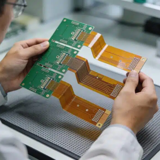
A flexible pcb – also called a flex circuit or FPC – is a printed circuit board whose rigid FR4 laminate is replaced with a thin polyimide film, so the copper circuitry bends, folds, and twists to fit the product instead of forcing the product around the board. That single change is why design teams move to flex when space, weight, or motion is the constraint, and it’s the work this page is about.
As one engineer put it on r/PrintedCircuitBoard, “Bending FR4 always has a risk of breaking, so I would go for a flex pcb 10 out of 10 times rather than bend a rigid PCB.”
System-Level Reliability
The pain show up at the system level. A cable assembly or a stack of rigid boards joined by connectors carries the dominant failure mode of any electronic assembly – the solder joint and the interconnect. When that assembly live inside a wearable, a camera module, or an under-hood automotive run, vibration and repeated motion fatigue those joints until something cracks. A flexible printed circuit replaces that cabling and those connectors with one continuous etched conductor, removing the points that fail first. Teardown data attributes a 30-45% reduction in interconnect-related defects to replacing discrete wiring with flex assemblies, depending on connector count, alongside a 10-25% weight drop in compact products.
The Engineering Trade-off
The honest version: flex is not the right answer for every board. If your design ships flat in consumer volumes and never bends after assembly, rigid FR4 usually wins on cost and design freedom. Flexible PCBs earn their place when the board has to fit a 3D shape, survive repeated motion, shed connectors, or cut weight — and that is exactly the decision this page helps you make. With 16+ years and 500,000 m²/yr of EMS capacity, PCBark builds both sides of that trade-off in-house, so the recommendation you get is engineering, not a sales reflex.
Flex PCB Types & Materials: Single, Double & Multilayer FPC Construction
Here’s the counter-intuitive part most capability pages skip: in flex, more layers isn’t better. The minimum bend radius a flexible circuit can survive scales with its layer count – roughly 6× the flex thickness for single-sided, 12× for double-sided, and 24× for multilayer construction. A multilayer flex need four times the bend radius of a single-sided one, so adding layers to a tight-bend wearable can make the design physically un-buildable. The right lever is often via architecture, not layer count: a 6-layer HDI flex can carry the functionality of an 8-layer rigid board. Choosing a stack-up is a balance of bendability, density, and reliability – not a race to the highest layer count.
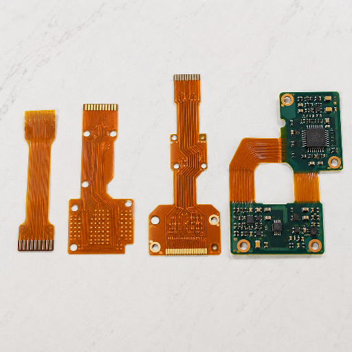
Flex PCB construction types (IPC-2223 / IPC-6013) — layer count, bend behavior, and typical use
IPC-2223, the sectional design standard for flex, formalizes this in five board Types, which map directly onto how PCBark quotes a job:
High-Precision FPC
| Construction | IPC Type | Min bend radius | Typical use |
|---|---|---|---|
| Single-sided FPC | Type 1 (1 conductive layer) | ≈ 6× flex thickness | LED strips, sensor flex, dynamic-flex jumpers |
| Double-sided FPC | Type 2 (2 layers, plated holes) | ≈ 12× flex thickness | Connectors, display flex, wearables |
| Multilayer flex | Type 3 (3+ layers, PTH) | ≈ 24× flex thickness | Dense camera & medical modules |
| Rigid-flex | Type 4 (rigid + flex combination) | Per rigid-flex zone design | See our rigid-flex PCB manufacturer page |
Material choice is where flex reliability is won or lost, and it’s the area where an unknown brand has to prove it won’t silently downgrade the build. We treat three decisions explicitly:
Polyimide base, not polyester.
Polyimide film holds thermal stability to about 260 °C versus roughly 150 °C for polyester, and it damps shock and vibration. Substituting a cheaper polyester laminate where performance matters leads to premature failure, a substitution we don’t make.
RA copper for bending.
We prefer RA in most places that move – this gives us a long horizontal grain that doesn’t get broken by flexing; electro-deposited (ED) has a vertical grain that fails under tension and doesn’t take bending quite as well, and costs less, so ED is mostly used in stationary locations.
Coverlay-not solder mask.
Standard FR4 solder mask is very brittle, and cracks upon flexing. flex uses a laminated polyimide coverlay (usually 1mil polyimide, 1mil adhesive). Adhesiveless laminates -where the copper attaches to polyimide via no adhesive layer to absorb moisture or crack out-build thinner, more dimensionally stable, higher temperature products.
PCBark Flex PCB Capabilities, Full 3-Tier Spec Envelope
Most flex manufacturer pages publish a single number per parameter, which tells you a ceiling but not where routine production ends and advanced engineering begins. That gap is exactly what makes buyers wary, as one put it, “FPCs are more expensive and yield rates are low, with FPC your design will likely determine quality.” We answer it the opposite way. The PCBark Flex PCB Capability Envelope below publishes three tiers for every parameter, Standard (routine, with the best yield and price), Best (advanced production), and Maximum (engineering ceiling) — so you can place your design inside the envelope before you ever request a quote, and we can both see whether a spec sits in routine territory or pushes the limit.
Read More
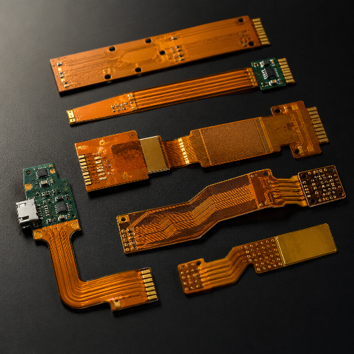
PCBark Flex PCB Capability Envelope — Standard / Best / Maximum Across 18 Parameters (Source: PCBark Process-Capability Data)
| Parameter | Standard | Best | Maximum |
|---|---|---|---|
| Layer count | 1–2 | 2–6 | 10+ |
| Base material | Polyimide | PI, adhesiveless | High-reliability flex material |
| Board thickness | 0.08–0.20 mm | 0.05–0.30 mm | Project-based |
| Copper thickness | 0.5–1 oz | 0.5–2 oz | 3 oz |
| Copper foil type | ED copper | RA copper | High-flexibility RA copper |
| Min. trace / space | 0.10 / 0.10 mm | 0.075 / 0.075 mm | 0.050 / 0.050 mm |
| Min. mechanical hole | 0.25 mm | 0.20 mm | 0.15 mm |
| Min. laser via | 0.10 mm | 0.075 mm | 0.050 mm |
| Hole copper thickness | ≥15 µm | ≥20 µm | ≥25 µm |
| Parameter | Standard | Best | Maximum |
|---|---|---|---|
| Surface finish | ENIG, OSP | ENIG, Imm. Silver, Imm. Tin | ENEPIG, Hard Gold, custom |
| Coverlay color | Yellow, black | + white | Custom colors |
| Stiffener material | PI, FR-4 | + stainless steel | Aluminum, steel, custom |
| Min. bend radius | ≥10× thickness | ≥6× thickness | ≥3× thickness |
| Dynamic bend cycles | 1,000+ | 10,000+ | 100,000+ |
| Max. finished size | 250 × 400 mm | 400 × 500 mm | 500 × 600 mm |
| Impedance control | ±10% | ±8% | ±5% |
| Testing | 100% E-test | + AOI, flying probe | + impedance + reliability |
| Gold finger | Available | Selective hard gold | High-durability |
Engineering Insight
Two columns are worth reading carefully, because they’re where hidden cost lives. The copper-foil row is a real engineering decision, not an upsell: RA copper is mandatory for dynamic flex but costs more, while ED copper is fine, and cheaper, for static designs that only bend once at install. And the trace/space Maximum of 0.05 mm is genuine fine-line capability: adhesiveless 2-layer flex as thin as 30 µm with 15 µm line and space is produced at volume using Laser Direct Imaging, which sits in more than 80% of fine-line flex mass production. Where a competitor’s single-value sheet stops at about 0.089 mm, our published envelope shows the routine, advanced, and ceiling cases side by side.
Flex PCB vs Rigid PCB vs Cable Assembly, Performance & Real Cost
Buyers tell us flatly that flex worries them on price — “flex circuits do tend to be more expensive than comparable rigid PCBs for the same size and number of layers, especially in prototype.” That’s true at the bare-board level, and it’s worth saying plainly: polyimide flex laminate runs 2–3× the cost of FR4, and a finished flex board can land at 3–8× a comparable rigid one, because flex uses 40–50 process steps against rigid’s 20–30. Stopping the comparison at the bare board is the mistake.
Read More
COST ANALYSIS
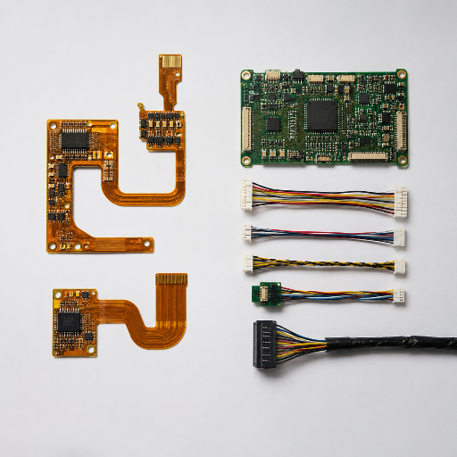
Flexible PCB vs Rigid PCB + Cable Assembly — Where Each Wins (Quantified, Not High/Med/Low)
| Factor | Flexible PCB | Rigid PCB + Cable Assembly |
|---|---|---|
| Bare-board cost | 2–3× material premium | Baseline (FR4) |
| Interconnect defects | 30–45% fewer (connectors removed) | Connector/solder joints = top failure source |
| Weight (compact product) | 10–25% lighter | Heavier (cables + connectors) |
| Assembly & test | One line, one test run | Board + connector + cable, multiple test cycles |
| 3D / dynamic fit | Folds & flexes to the enclosure | Fixed shape, bend risks breakage |
| Best when | ≥5 connectors, space/weight critical, motion | Flat, static, high volume, cost-driven |
This is the contradiction worth internalizing: rigid isn’t always the cheaper procurement decision. Once a design connects five or more boards or replaces a cable assembly, eliminating those connectors, cables, extra production lines, and repeated test cycles often makes the total assembled-system cost lower than the rigid-plus-cabling path, the published breakeven sit around 500 units.
Total Cost of Ownership, The Part The Per-Board Quote Hides
In multi- board designs substituting a “cable assembly” with a flex circuit typically reduces connector/cable costs and “cuts field failures by 30-45%” for “interconnect-related field defects”, and typically reducing board “mass by 10-25% in space- constrained products”. The fabrication cost per-piece “is 30-80% higher per board but is cost-effective once they substitute 5+ connectors at volume”.
Silver-tier estimate, figures are published industry-average TCO data (Epec, AIVON, bestfpc), not PCBark first-party measurements. We size the trade-off against your bill of materials during DFM.
Flex PCB Applications & Industries: From Wearables to Camera Modules
Why designers may pay too much: Often, companies start specifying a “custom flex pcb” then figure out what “layer count” fits, rather than start by exploring how the intended use can impact the need. designers focusing on camera modules and wearable electronics regularly trip up: “traces stacked directly on top of each other on a double-sided flex will crack with repeated bending unless reinforced with anchors and teardrops, and when the bending element delaminates”. Because minimum radius depends on layer count (6x single sided, 12x double-sided and 24x multilayer as a function of flex thickness), the physical dimension of your product determines the number of layers, not its schematic. Our flex pcb design Review, therefore, takes place at the quotation stage of your project: we then size the application against its appropriate tier within our capability suite, ensuring a wearable sensor fit a dynamic “Maximum” specification, not an LED string that simply bends 90 degrees upon installation.

Wearables & Medical
Activity trackers and patient monitors, hearing-assist devices, implantables, and diagnostic equipment for CT, MRI, and ultrasound. These need biocompatible polyimide, RA copper for repeated bending, and coverlay or conformal coating that survives repeated disinfection.

Automotive & Industrial
Under-hood and in-cabin runs where polyimide’s vibration damping and the deletion of connectors raise reliability. Flex replaces discrete wiring in space- and temperature-constrained assemblies.

Consumer & Camera Modules
LED strips, foldable and hinged devices, and camera-module interconnects where 0.05 mm fine-line and tight, repeated bends are the design driver.
Comms & High-Density
HDI flex and high-density interconnect for antennas, modules, and dense digital boards, where a 6-layer HDI flex replaces an 8-layer rigid stack and controlled impedance matters.
Ultimately, the same reliability issue you were presented with on this page can be solved: a flexible board eliminating “interconnects” won’t have a field failure within the printed circuit assembly (PCA). Whether your needs span a single-layer flex sensor, multilayer-based camera module, or dynamic “body-worn” flex, your product will determine its structure, and we help size the investment as a flex pcb design decision, not provide an off-the- shelf estimate.
Quality, Testing & Certifications for Flex PCB
Lower-down the green fields: trust in an offshore flex isn’t about the country – it’s brand-specific evidence. Engineers claiming to have bought from China several years in a row say it clearly: “I’ve been buying pcbs from Chinese companies for years now, and am very happy with their turn-around and quality.” The purpose of this section is therefore not to defend China; it’s to anchor our marketing statements to the precise standards a buyer can audit.
IPC-6013 Class 2/3
Flex acceptance & performance
IPC-2223
Flex / rigid-flex design
IPC-A-600
Board acceptability
ISO 9001
Quality management system
100% E-test
+ AOI · flying probe · TDR
What “±5% impedance” and “Class 3” actually mean
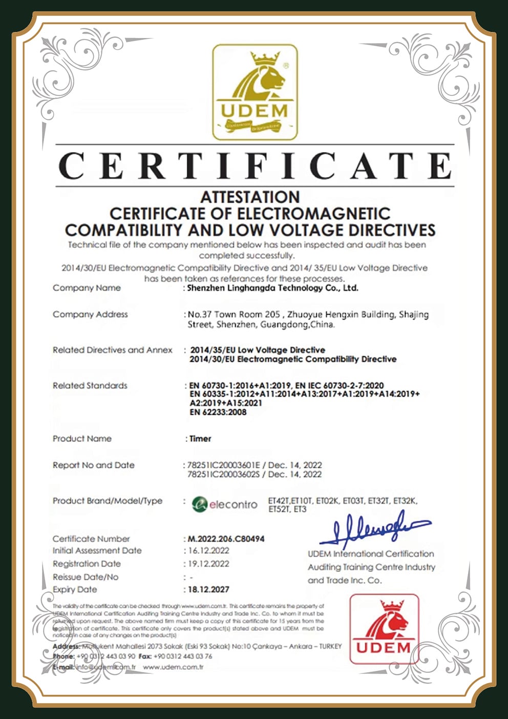
Our 5% controlled-impedance tolerance is Class-2 standard controlled impedance under IPC-6013; the tightest class 3 aerospace work falls between 2-5%. We state that frankly rather than implying every board is built to the max band. PCBark’s flex pcb manufacturing runs to IPC-2223 design rules and IPC-6013 acceptance under an ISO 9001 quality system, serving commercial, industrial, consumer, automotive, and medical flex. We are not an itar-registered defense supplier – if your program requires ITAR or AS9100, inform us up-front so we can route it properly rather than overstate our scope.
Flexible boards are classified on two orthogonal axes under IPC and blending them is a common and expensive mistake. Board Type (1-5) refers to construction and layer count; Performance Class (1-3, determined by IPC-6011)refers to inspection strictness and dependability. They’re orthogonal: a single-sided Type 1 can be built to class 3, and increasing layers doesn’t raise the class. Even more relevant for flex, neither one is the dynamic-flex axis – that one is Installation Use B, where the bend-cycle count is set on the purchase order and verified to IPC-6013 procedures. A class 2 board specified Use B at 100,000 cycles is a superior dynamic-flex part to a class 3 board left at the default one time install bend.
Every board is 100% electrically tested as a baseline; advanced and dependability tiers add automated optical inspection, flying-probe test, TDR impedance verification, thermal cycling, and microsection. The honest caveat: over-specifying tests your design does not need inflates price and schedule, so we match the test plan to the class it actually requires.






×
Interactive Flex PCB Engineering & Design Tools
Flex PCB Stackup & Layer Selector
Pick your layer count, flex duty, and application — see the construction type, minimum bend radius, copper, and the PCBark capability tier it lands in.
Access Tool
Flex Bend-Radius & Dynamic-Cycle Estimator
Enter your flex thickness, bend radius, and how often the board flexes. Get the bend ratio, an estimated cycle band, the copper to use, and the PCBark tier — based on IPC-2223 / EE Times copper-strain rules.
Access Tool
Flex-vs-Rigid TCO Estimator
Flex costs more per bare board — but deleting connectors and cables can lower total system cost. Enter your design to see where the trade-off lands. Estimates use published industry-average TCO ranges, not a quote.
Access Tool
FAQ — Flex PCB Manufacturer: Common Buyer Questions
What is a flex PCB?
A flex PCB (flexible printed circuit, or FPC) is a printed circuit board built on a thin polyimide film instead of rigid FR4, so the copper circuitry can bend, fold, and flex to fit a 3D shape or survive repeated motion. It’s used to replace discrete wiring and connectors, save space and weight, and fit electronics into curved or moving assemblies.
What is the difference between flex and rigid PCB?
A rigid PCB holds its shape on FR4; a flex PCB bends on polyimide. The practical difference is failure mode and fit: rigid boards joined by connectors fail at the interconnects, while a flex circuit replaces those connectors with one continuous conductor and folds into the enclosure. Rigid wins when the board is flat, static, and high volume; flex wins when shape, motion, weight, or connector count drives the design.
How many bend cycles can a flex PCB survive?
It depends entirely on bend radius, copper type, and layer count, there’s no single number. Rolled-annealed copper at a generous radius can exceed 1,000,000 cycles, while the same artwork on ED copper or a tight radius may crack below 1,000. PCBark rates dynamic-flex builds to 100,000+ cycles in the Maximum tier, qualified against the radius and material in your design under IPC-6013 Use B.
Is offshore / China-made flex PCB reliable?
Flex reliability is set by material, design, and process control, not by country of origin, and most polyimide flex worldwide is already made in China on cost grounds, with engineers widely reporting good quality and turnaround. What separates suppliers is brand-specific proof: cycle-rated bend data, IPC-6013 class, controlled impedance tolerance, and DFM engagement. That’s what our capability envelope and test documentation exist to show.
What is the smallest trace and space you can make on flex?
Our Maximum tier reaches 0.05 mm (50 µm) trace and space, produced with Laser Direct Imaging, the fine-line process behind more than 80% of high-density flex mass production. Standard production runs 0.10 mm, with 0.075 mm in the Best tier; we quote the tier that matches your density and budget.
Why are flex PCBs more expensive than rigid PCBs?
At the bare-board level a flexible PCB runs 3–8× a comparable rigid board, because polyimide laminate costs 2–3× FR4 and flex uses 40–50 process steps versus 20–30 for rigid. The premium is real, but on a multi-board product, deleting connectors and cables and consolidating test often makes total system cost lower than rigid plus a cable assembly, with breakeven near 500 units.
What is the difference between FR4 and flex material?
FR4 is a rigid glass-epoxy laminate rated to about 130 °C; flex uses polyimide film rated to roughly 260 °C that bends without cracking. FR4 also uses a brittle solder mask that cracks on a bend, whereas flex uses a laminated polyimide coverlay. For static bends, a semi-flex FR4 construction can cut material cost 30–40% — but it can’t do dynamic flexing.
What is coverlay in a flex PCB?
Coverlay is the flexible insulating film, typically 1-mil polyimide plus 1-mil adhesive, laminated over the copper traces to protect and insulate them. It replaces the rigid solder mask used on FR4, which would crack when the board bends. Coverlay material and placement are a primary driver of bend reliability, not a cosmetic layer.
Can PCBark do both flex fabrication and assembly?
Yes, PCBark is a full-turnkey EMS provider. One supplier handles DFM review, flexible PCB fabrication, component sourcing, flex PCB assembly, and functional testing, so design errors are caught before production rather than during it. We also build rigid-flex and multilayer flex for designs that need them.
![Drone PCB Design Guide: IPC Class & Manufacturing [2026]](https://pcbark.com/wp-content/uploads/2026/07/drone-pcb-design-guide-featured-150x150.png)