Get in touch with PCBark Company

Medical PCB Manufacturer, IPC Class 3 Boards & Turnkey Assembly
Reliability that holds inside your medical device, while mounted to a board inside an infusion pump or wearable on a patient, has to be built and traceable end-to-end. That means under one roof. That’s what we do.
- ISO 9001
- ISO 14001
- IATF 16949
- UL
- RoHS / REACH
- CE
- IPC Class 3 capable
4–32
layers (rigid, HDI, multilayer)
0.040 mm
min trace/space (any-layer HDI)
±5%
controlled impedance (TDR)
100%
AOI + X-ray + e-test
1–15 days
quick-turn to production
No MOQ
on prototypes + free DFM
Why Medical PCBs Demand a Different Standard
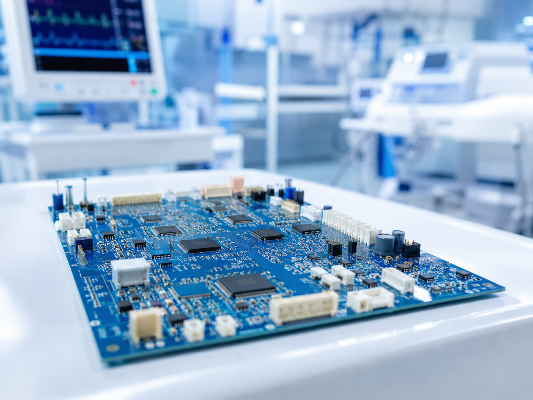
Quality escapes occur when a defective board still looks correct. Selecting the right board requires recognizing your real choice is between managing risk and buying on price. A circuit board on your diagnostic monitor, in a patient pump, or on your portable ventilator can’t afford to quietly die. Even one “quality escape” could prompt an FDA investigation and delay launch. (FDA medical device framework)
The challenge:
“Quality escape” boards can still appear perfect – passing routine functional checks on the bench and a rapid eye inspection before being packed, shipped, and experiencing months of in-device thermal stress, moisture, and vibration.
The medical-grade gap, in one line
A merely “working” printed board and one worthy of your design exist worlds apart – a gap narrowed only through build discipline (ipc class 3 discipline!), rigorously correct material selection and finish, and full lot traceability ready for auditor eyes. Anything less becomes a dangerous liability.
PCBark narrows that gap by adhering to a consistent Class 3 build protocol (IPC-6012), 100% boards inspection with automated checks and eye ball (automated optical inspection, x-ray), and careful process and material records for every job lot. You get a printed circuit board that will survive review-not one that simply turn on first power.
Medical PCB Capabilities, Board Types & Specs
Most of your patient monitors will need different board types. That high layer count in the console contrasts sharply with a wearable’s ultra-thin flex circuit requiring 100,000 bend cycles, or a portable device pushing functionality into an HDI architecture on the screen. (ISO 9001 quality management)
Review this Medical PCB Capability Matrix to understand the precise tolerances for different medical program board types in reality. (You’ll note the manufacturing process for each category refers to the same underlying documented Class 3 processes and materials)
SPECIFICATIONS MATRIX
| Board type | Layers | Min trace / space | Min laser via | Impedance | Finish | Typical medical use |
|---|---|---|---|---|---|---|
| Rigid multilayer | 4–32 | 0.075 / 0.075 mm | 0.10 mm | ±10% ±5% | ENIG, ENEPIG | Imaging, diagnostics consoles |
| HDI / any-layer | 4–32 | 0.040 mm | 0.050 mm | ±5% | ENEPIG, hard gold | Handheld & wearable compute |
| Flex (FPC) | 1–10 | 0.050 mm | 0.050 mm | ±5% | ENIG, ENEPIG | Catheters, ECG patches, sensors |
| Rigid-flex | 4–24 | 0.050 mm | 0.050 mm | ±5% | ENEPIG | Patient monitors, portables |
| Aluminum / MCPCB | 1–6 | 0.075 mm | — | — | ENIG | Surgical & exam LED lighting |
| Ceramic (Al₂O₃ / AlN) | 1–6 | 0.050 mm | — | — | NiPdAu | Sensors, high-temp modules |
| Rogers / RF | 2–32 | 0.050 mm | 0.050 mm | ±5% | ENIG, immersion silver | RF telemetry, wireless implants |
| Heavy copper | 2–32 | 0.15 / 0.15 mm | — | ±10% | ENIG | Defibrillator & power stages |
| Gold-finger / edge | 2–32 | 0.075 mm | 0.10 mm | ±10% | Hard gold 30–50µin | Modular & cartridge boards |
| Double-sided rigid | 2 | 0.10 / 0.10 mm | 0.10 mm | ±10% | HASL-LF, ENIG | Power & control sub-boards |
Medical-Grade vs Standard PCB, What Changes & Why It Costs
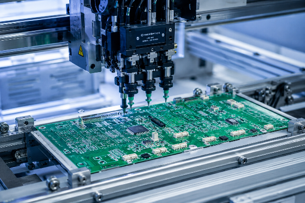
“Medical-grade” isn’t just marketing buzzword: it means a definitive improvement over basic (ipc class 2) quality, incorporating the stricter process and dimensional tolerances associated with IPC-6012 Class 3 boards-including higher plated hole copper amounts and tighter annular rings defined under IPC-A-600. these are the stringent requirements critical for approval. (FDA medical device recalls)
We’ve published a IPC Class 2 vs Class 3 Decision Guide comparing specs and explaining why the Class 3 specification makes sense for circuits within patient-connected systems where a failure means a critical loss of functionality.
| Attribute | Standard board (IPC Class 2) | Medical board (IPC Class 3) |
|---|---|---|
| Reliability target | Predictable service, occasional rework OK | Continued performance, no field failures tolerated |
| Min. annular ring | Relaxed; breakout allowed | Maintained 0.025 mm; no breakout |
| Plated hole-wall copper | ≥20 µm typical | ≥25 µm, verified by microsection |
| Inspection | Sample AOI | 100% AOI + X-ray on buried/blind vias |
| Traceability | Lot-level | Material + process record per lot |
Board costs go up for Class 3 boards because of tight tolerances (a narrower build window) and 100% inspection of every board and component – but even the tiny cost premium is dwarfed by the financial and reputational consequences of a failure.
The Cost-of-Failure View (ROI, Silver)
Individual recall events cost manufacturers an estimated $10M-$600M depending on scope. Against exposure like that, the trade-off favours Class 3 traceability.5B each year. So, a fully traceable Class 3 board is more like risk-management than a cut-to-a-shaving item. All values are general industry figures, not based on specific PCBark projects. However, we can tailor our assessment for your volume needs.
That’s precisely why we also build for IEC 60601-1’s crawl/clearance requirements, the FDA’s accepted electrical-safety standard for medical electrical equipment, which is mandatory for all US submissions since last December.
Quality, Compliance & Traceability
Many of our customers’ first question to us is, “Are you ISO 13485 certified?” The answer is more complex than simply yes or no-and will fundamentally change how you should look at a PCB fabricator. (ISO 13485:2016)
Without ISO 13485 certification, most buyer assume a PCB manufacturer is unable to serve any class II or class III devices -and here’s where most get it wrong.
Where ISO 13485 actually lives
A PCB manufacturer without ISO 13485 is widely assumed unable to supply any Class II or Class III device, and that assumption is where most buyers get it wrong. The honest answer depends on who holds the device-level quality system. ISO 13485 is a device-level quality system owned by the device’s legal manufacturer-the medical device maker-and audited by the FDA. The manufacturer(fabricator) feeds into that system. a supplier that has IATF 16949 automotive quality standards, ISO 9001 process controls, and ipc class 3 traceability, is able to supply product that the OEM(you!) can qualified and roll into 13485 systems.
Put plainly, the device’s submission’s certification is ultimately yours. What you need to expect from the fabricator is process discipline and a documented trace of its every decision. PCBark is your solution. All fabrication is driven by quality control based on total inspection and per-lot documentation, not spot-checks.
What we hold
- ISO 9001 & ISO 14001 (since 2011)
- IATF 16949 automotive-grade process control
- UL recognition & RoHS / REACH (since 2014)
- CE marking support
- IPC-6012 Class 3 build capability
What we give your auditor
- Material certs (laminate, copper, finish) per lot
- Process travelers with date / line / operator
- Microsection & impedance (TDR) reports
- 100% AOI and X-ray records
- Component traceability via authorized distributors
“We don’t ask customers to take ‘medical-grade’ on faith. For every Class 3 lot we keep the microsection, the impedance trace, and the AOI record, so when your auditor opens the design history file, the evidence is already there.”
— PCBark Engineering Team, Process QualityDOCUMENTED EVIDENCE (SCROLL →)
Medical Device Applications We Power
Choosing the wrong board architecture often makes cost problems resurface later, when a rigid board might flexesa solder joint after few thousand cycle, or a board overbuilt to deal with complexity wastes a margin for a simple sensor.
The risks for failure vary by class and device. PCBark uses an approach that matches the construction to those risks, rather than relying on a single line-fit and compromise solution applicable to every type of device – whether it’s for high power in CT imaging console’s or delicate, low power skin-wearable sensors – we use ipc class 3 on ISO 9001 processes that maintains tolerance to ±0.040 mm on space/trace with tight ±5% impedance tolerances and hole-wall copper to 25µm.
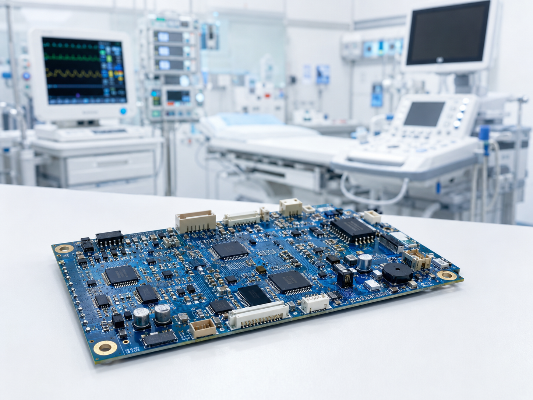
Match your application to the right construction with our Medical Device-to-PCB Type Selector.
| Medical device | Recommended board | Driving requirement |
|---|---|---|
| CT / MRI imaging console | High-layer rigid multilayer | Signal integrity, layer count, impedance |
| X-ray detector panel | HDI multilayer | Fine pitch, low noise |
| Patient monitor | Rigid-flex | Durability, fewer connectors |
| Wearable ECG / biosensor patch | Flex (FPC) | 100,000+ bend cycles, low weight |
| Hearing aid / small implant | HDI flex | Extreme miniaturization |
| Infusion & syringe pump | Rigid multilayer | Long-term reliability |
| Oxygen concentrator circuit board | Rigid + heavy copper | Power handling, thermal |
| Pulse oximeter PCB | Rigid-flex / flex | Compact, light, durable |
| Blood-glucose monitor | Flex / HDI | Small footprint, low cost at volume |
| Surgical robot controller | HDI + rigid-flex | High reliability, density |
| Defibrillator | Heavy copper rigid | High-current power stage |
| Ultrasound probe | HDI flex | High density, flexible routing |
Devices at the frontier are pushing into territory that are putting electronics inside the body. We actually patented the idea of putting a flex circuit on an implanted circuit with a patent published in 2024 by Cardiac Pacemakers Inc. EP4103270B1 for its invention of a body-safe flex circuit wrapped in an implanted housing that’s done away with traditional headers altogether. We’re at the forefront of what can be achieved using flex and rigid flex construction, and that’s reflected in what we do for medical equipment makers.
From Prototype to Production, Turnkey Workflow
Let A provider’s lead times to slack put a buyer out of your market window or to cause you to lose a costly medical lot with a redesign. Perhaps the most perilous threat is the “quality escape,” where you believe your circuit passes everything you run from the test to its first 30 days in the field… but that isn’t what has happened after a board passes first tests only to then reveal its flaws within months in field use. (IEEE electronics standards)
PCBark’s ipc class 3 assembly process covers you with single documentation across all its lines from fabrication to vol; all manufacturing operations are completed in our single facility (no division of production). We use eight assembly lines for each component and, since everything’s processed internally, we can offer you 100 percent AOI and x-ray, plus copper of .25 mill (to achieve and maintain a 5% impedance across each component from start to finish on all boards, whether your lot comes back as custom or comes out of inventory from your part’s shelf life in our storage) with lot traceability back to the date the base component was made.
PCBark’s ipc class 3 assembly process covers you with single documentation across all its lines from fabrication to vol; all manufacturing operations are completed in our single facility (no division of production). We use eight assembly lines for each component and, since everything’s processed internally, we can offer you 100 percent AOI and x-ray, plus copper of .25 mill (to achieve and maintain a 5% impedance across each component from start to finish on all boards, whether your lot comes back as custom or comes out of inventory from your part’s shelf life in our storage) with lot traceability back to the date the base component was made.
[ STEP 01 ]
DFM review (front-end CAM)
Every design get a proactive Design-for-Manufacturing check, clearance, trace width, stack-up, before tooling. Catching a clearance error here prevents a scrapped medical lot later.
[ STEP 02 ]
Transparent sourcing
Components come through authorized distributors (Arrow, Avnet, DigiKey) with full traceability, no grey-market counterfeits in a life-critical board.
[ STEP 03 ]
Fabrication
IPC Class 3 build across rigid, HDI, flex and rigid-flex, with controlled impedance held to ±5% by TDR.
[ STEP 04 ]
SMT & assembly services
8 SMT lines, up to 9 million placements per day, down to 0201 and 0.30 mm BGA pitch, SMT and through-hole, leaded or lead-free.
[ STEP 05 ]
Test & inspection
100% AOI and X-ray, plus ICT, flying-probe, burn-in and functional test to your protocol.
[ STEP 06 ]
Delivery
Quick-turn PCB prototypes in as little as 1–15 days, scaling to volume on the same documented process.
Procurement Guide, Pricing, Lead Time, MOQ & Quoting
The #1 problem that medical product manufacturers bring up time and again is the hidden (or “soft costs”), which include cost overruns related to rework that drive product landed cost by 20 percent; overhead costs due to excessive communications; and unanticipated tariffs that convert a seemingly low “cost”… to your purchase into an inflated invoice. (FDA supplier quality controls)
Since PCBark bases its estimates on current market pricing instead of a teaser figure, you’ll always know what directly impacts costs. Rather than luring clients in with a bargain and then inflting the estimate price after you submit their POs, we make the true cost clear on the outset. We maintain all quality control in-house, along with certified bikapafo Loteguk standards (IATF 16949). What This Means To you.
Since PCBark bases its estimates on current market pricing instead of a teaser figure, you’ll always know what directly impacts costs. Rather than luring clients in with a bargain and then inflting the estimate price after you submit their POs, we make the true cost clear on the outset. We maintain all quality control in-house, along with certified bikapafo Loteguk standards (IATF 16949). What This Means To you.
Our procurement posture
You won’t pay anything to prototype with free DFM from our PCB experts and you’ll never incur additional fees no matter the order volume (even one piece). Turnkey or consignment options allow you to retain complete control of the BOM. Lead time as well as our pricing are listed per each design on request and are in accordance with your standards.
It’s of the utmost importance for us that your board costs you the fewest possible cost in use over time; for this reason, we’ll shoulder risk management tasks ourselves in an effort to save you money (while ensuring efficiency, not by cutting corners in production).
What drives your medical PCB price
- Construction and Classification: ipc class 3, HDI vs rigid or rigid-flex structure, and board level count.
- Materials used: From standard FR-4 material to other types, such as high-Tg, Polyimide flex and Rogers RT laminates for high-performance apps.
- Specialty features and Finishes: Available options include ENIG, ENEPIG, Gold fingers, Vias in Pads and Controlled impedances.
- Scope of Test: Basic AOI/x-ray through advanced testing such as; ICT, Burn-in and Functional testing, as desired to spec.
- Production volume and schedule: prototypes are readily available along with scheduled production volumes to match your demand.
RESOURCES / SYSTEM TOOLS
Medical PCB Engineering Tools
Technical utilities for device specification, IPC compliance comparison, and project quotation.
System Ready
Build your next medical board with a partner that documents everything
Send your stack-up and BOM for a free DFM review and an itemized quotation -no MOQ on prototypes, full Class 3 traceability included.
Request a Quote →At the fabricator level, look for ISO 9001, IATF 16949 or equivalent process control, UL, RoHS, and demonstrated IPC-6012 Class 3 capability with per-lot traceability. The honest version is simple: ISO 13485 is the device maker’s own quality system, the fabricator feeds documented evidence into it rather than replacing it.
Yes. ISO 13485 governs the legal device manufacturer’s quality system, not every component supplier. Many Class II and III devices are built on boards from fabricators qualified by the OEM through audits, IPC Class 3 build records, and material/process traceability, which is what PCBark supplies.
Most medical boards use FR-4 or high-Tg FR-4. Polyimide is standard for flex and rigid-flex; Rogers and PTFE laminates are used for RF and high-speed telemetry. Exotic materials are the exception, not the rule, the right call is application-driven.
Sterilization compatibility is mainly a material, finish, and conformal-coating decision, autoclave, EtO, and gamma each stress the board differently. We review the intended method during DFM and recommend laminate, finish (e.g. ENIG), and coating accordingly.
Yes, there’s no minimum order quantity on prototypes, and quick-turn builds run in roughly 1–15 days. The same documented Class 3 process scales straight into production, so your qualified board doesn’t change when volume does.
Every board gets 100% AOI and X-ray (for BGA and buried/blind vias), plus 100% electrical test. We add ICT, flying-probe, burn-in, and functional test to your protocol for assembled boards.
We support medical OEMs alongside automotive, industrial, and aerospace customers, and can share relevant capability evidence and process documentation under NDA. Contact us to discuss your program and what references apply.