Get in touch with PCBark Company

PCBark · Drone & UAV Electronics Manufacturing
Drone PCB Manufacturing & Assembly: Lightweight, Flight-Ready UAV Circuit Boards
A drone PCB is the printed circuit board that drives flight control, power propulsion, sensing, and communication at the heart of a UAV – and the manufacturing processes it follows ultimately determine if your aircraft successfully achieves flight or fails on deployment. PCBark makes these boards from DFM through sourcing and full turnkey assembly on a single production line: fabricate, SMT assembly, then functionally test.
Request a Drone PCB Quote
8
In-house SMT lines
0201
Min component / BGA · QFP · CSP
FR-4 → Rigid-Flex
5 substrate families
1–15 days
Prototype to volume turn
IPC Class 2/3
Build standard option
Turnkey
DFM → fab → assembly → test
SYSTEM RELIABILITY
Why Drone PCBs Fail in the Field, and the Manufacturing Decisions That Prevent It
Drone PCBs face the same vibration, shock, and thermal-cycling stresses tracked by NASA’s electronic parts and packaging reliability program, which is why field survival is a manufacturing problem, not a schematic one.
Most drone PCB failures aren’t design flaws – they become apparent only when in use, when vibration, temperature extremes, and the weight of the payload all come to bear on the board. A perfectly fine prototype might show its first crack after 200 hours of rotor vibration or a brownout from a sudden surge… in motor current next to an unprotected signal line.
The solution is almost never a revised schematic diagram. Instead it relies on better materials choices and fabrication- copper weight, symmetric layout, solid solder joints, higher levels of test coverage, and how it fits in the aircraft’s real flight regimen.
When constraints of board space, trace spacing, and component placement often limit the number of layers used, each choice is inevitably a trade-off against the weight burden that carries much of our air time. This makes the guidance provided by manufacturing specialists invaluable, rather than simply reviewing a polished set of schematics and plans.
Field failure (pain)
Root cause
PCBark manufacturing control
Solder joints crack after flight hours
Continuous rotor vibration + launch/landing shock fatigue joints (per MIL-STD-810 random-vibration profiles)
X-Ray + AOI joint verification; IPC-A-610 Class 2/3 acceptance; optional conformal coating per IPC-CC-830
Flight controller resets under throttle
High-current ESC/PDB traces couple noise into control signals (EMI)
Controlled-impedance stack-up + ground-plane separation, verified on our impedance test bench
MOSFETs / power stage overheat
FR-4 conducts heat at only 0.3 W/m·K; power zones exceed 85°C
2 oz+ copper, thermal vias, or aluminum-core PCB in motor-drive zones
Board too heavy, payload/endurance drops
Over-specified layer count and copper add grams that cut flight time
Weight-driven stack-up: right-sized layers, HDI/rigid-flex where it saves mass
Latent defect ships to the customer
Visual-only inspection misses BGA voids and opens
Flying-probe e-test + ICT + X-Ray + function test before shipment
We start every drone PCB quote using a list of common flight-related failures, instead of the same one-size-fits-all templates most board shops use. We’re manufacturing partners, engineers for flight, not just circuit board fabricators.
Material System
Drone PCB Types & Material Selection, FR-4, Aluminum, Rogers, Polyimide & Rigid-Flex
Substrate thermal behaviour, from FR-4 to ceramic cores, is documented across IEEE electronics packaging research and it’s what separates a board that sheds heat from one that cooks.
A misstep with a drone PCB board material will result in overheating- a power supply component exceeding 85 °C, or the flight of a heavier aircraft carrying non-contributing copper that consumes battery life at an alarming rate-thus sacrificing operational range, possibly beyond reach. Many a UAV flight-time budget has evaporated, unbeknownst, on this simple design decision.
While many may assume that any flight application can benefit from an aluminum core PCB, this isn’t always true. Aluminum substrates are best suited for motor drives and power circuits that have a large area exposed to ambient conditions to manageheat;they increase weight and cost otherwise. Whereas the many different stack-ups offered by other sources, and simply followed blindly on our production line for whatever you order,we’ll match materials for your airframe’s temperature demands-verifying each step with temperature data we collect and analyze for controlled impedance during design.
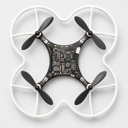
The Drone PCB Material Selection Matrix
The honest version of material choice is a trade-off, not a free upgrade. You pay for high-conductivity substrate in weight and cost, so we compromise deliberately and place premium material only in the thermal hot zones.
| Material | Thermal conductivity | Relative weight | Best-fit drone zone |
|---|---|---|---|
| Standard FR-4 | ~0.3 W/m·K | Baseline | Flight controller, sensor & logic boards |
| High-Tg FR-4 (TG170) | ~0.3–0.4 W/m·K | Baseline | Mixed power/logic boards run warm |
| Aluminum-core (MCPCB) | >10× FR-4 | Heavier | ESC / power distribution / motor-drive zones |
| Rogers / PTFE | Low-loss at RF | Light | 2.4 GHz+ RF, video transmission, GPS antenna |
| Polyimide / Rigid-Flex | >250°C Tg (PI) | Lightest in 3D | Folding stacks, arm wiring, weight-critical UAVs |
Higher performance levels (for 170 W/mK aluminum nitride versus 0.3 W/mK FR4) are available when thermally critical motor power components require them-and we ensure the spending is directed intelligently where your UAV application will most benefit.
An agricultural spraying drone could use an aluminum motor controller card but light FR4 for its ESP32 or STM32 flight control board, for example, while a delivery drone needing high-frequency communications at 2.4 GHz only puts its Rogers RF circuits where they’re needed for communications and antennae, and an aerial imaging drone that must operate through complex aerial environments uses a rigid-flex layer stack to efficiently locate its many sensor outputs.
The Drone Board-Type Map
The modern unmanned aerial vehicle doesn’t use a single circuit board-the airframe’s components are usually composed of several specialized boards that vary in board thickness, materials, and the importance placed on specific areas during functional testing, and so any one-size-fits-all solution for a “drone pcb” is rarely the right answer.
| Board type | Typical layers | Key constraint | Material lean |
|---|---|---|---|
| Flight controller (FC) | 4–8 | Signal integrity for IMU/gyroscope/accelerometer + microcontroller | FR-4 / high-Tg |
| Power distribution board (PDB) | 2–4 | High-power copper, heat spreading | 2 oz+ Cu / aluminum-core |
| Electronic speed controller (ESC) | 2–4 | MOSFET thermal path, current density | Aluminum-core / thick Cu |
| RF / video transmission (VTX) | 4–6 | Controlled impedance, low loss | Rogers / PTFE |
| GPS / sensor / telemetry module | 4–6 | EMI isolation, antenna ground | FR-4 + RF section |
| All-in-one (AIO) board | 6–8+ | FC + ESC + PDB integrated; tight thermal budget | Mixed / HDI |
Show us the block – or hand us the drone – and we map each discrete IC on the printed circuit board to the right substrate and number of layers even before we cut a panel. Our lines can build the attendant dense, multilayer HDI PCBs for dense multi-layer drone designs, or develop the hybrid rigid-flex circuits that save weight in folded UAV stacks in fold-down applications.
Not sure which substrate fits your board?
Get a free DFM review of your drone PCB →Drone PCB Design & DFM, Weight, Signal Integrity, Thermal & EMI
Controlled-impedance and signal-integrity targets for high-speed drone nets follow established IEEE signal-integrity design literature, which we hold to… on the bench rather than by assumption.
The fact is: not all layers are created equal. Contrary to a prevailing myth, a more copper-layered stack up doesn’t automatically translate to a more reliable drone PCB. All too often a 6-layer stack is simply inferior to a symmetrically laid out, well-grounded 4-layer board.
In practice, when we consider the flight of a drone, many careless 6-layer drone circuit boards lose to even a neatly routed, symmetrically laid out board with a substantial ground plane and controlled impedance 4-layer layout – because grounds and balance often trump the sheer count of layers.
This fundamental insight into what really constitutes a well-manufactured product underpins the entire DFM design review at the heart of all the drone boards that come through our shop. As we transition to the PCB fabrication process we tune your board around your target weight budget through our DFM analysis for drone circuit boards based on four interlocking design adjustments:
Engineering note, the four drone PCB design levers
01 Weight
every ounce added to the PCB directly reduces either flight time or payload, and so the PCB design team rightsizes, rather than overloads the stackup with copper and layers.
02 Signal integrity
targets (50 single-ended; 100 differential) and routed trace-spacing guidelines (for 3 trace-width min between traces that’s typically 0.2mm trace, 0.6mm gap) suppression crosstalk to levels above 2.4GHz.
03 Thermal
keep operating temperature at less than 85°C with thermal vias, while 2oz+ copper conduct thermal energy away from MOSFETs into the inner layers.
04 EMI
the designers’ careful work at the power-control and RFI-boundary isolates the traces routed for discrete RF and high-speed control signal paths from any noisy power distribution nets and eliminates unnecessary vias for such critical pathways.
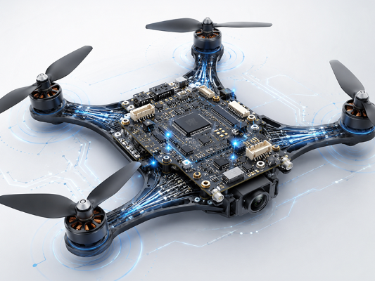
Hover to View Test Data & Insights
System Specifications
Custom Drone PCB Manufacturing vs. Off-the-Shelf & Generic Suppliers
For commercial and beyond-visual-line-of-sight UAVs, board choices ultimately answer to FAA unmanned aircraft systems requirements a bar an off-the-shelf hobby board rarely targets.
While off-the-shelf FC boards and off-the-shelf broker quotes PCBs are still good until you’ve to meet a specific weight or volume target and temperature and volume budget becomes critically important at some stage – these differences become measurable: – At a custom drone FC and assembly stage, the differences become tangible.
Dimension
Off-the-shelf board
Generic PCB broker
PCBark turnkey
Drone-specific DFM
Off-the-shelf:None (fixed design)
Generic:Rarely (prints your file)
PCBark:Weight/thermal/EMI review per board type
Material choice
Off-the-shelf:Fixed
Generic:Limited menu
PCBark:FR-4 → aluminum → Rogers → rigid-flex
Test coverage
Off-the-shelf:Batch sample
Generic:Bare-board only
PCBark:X-Ray + AOI + ICT + flying-probe + function
Traceability
Off-the-shelf:Low
Generic:Fragmented
PCBark:Single-system DFM→fab→assembly→test
Prototype → volume
Off-the-shelf:Not scalable
Generic:Re-quote / re-tool
PCBark:Same line, 1–15 day turn
Standard
Off-the-shelf:Unspecified
Generic:Class 2 typical
PCBark:IPC Class 2 or Class 3 on request
An off-the-shelf board may serve for hobby use, yet for production drone operations needing to be qualified for harsh environments, endure long service and be produced in volume; custom drone assembly of a specialized drone flight controller is the lowest risk pathway.
Quality, Certifications & Compliance, IPC, ISO, IATF, UL, RoHS
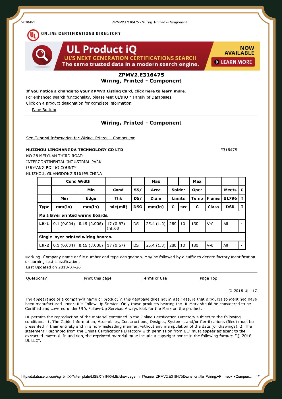
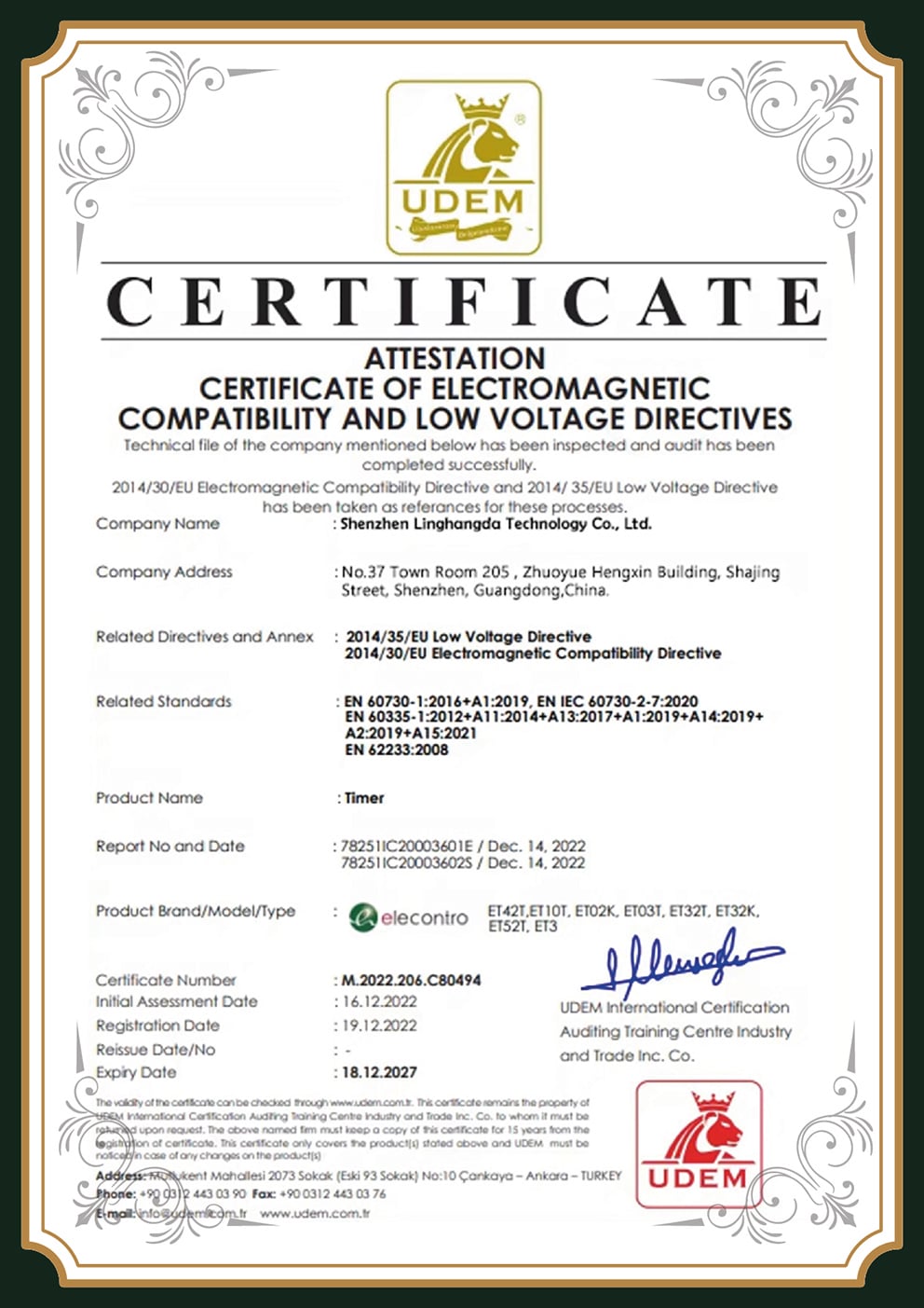
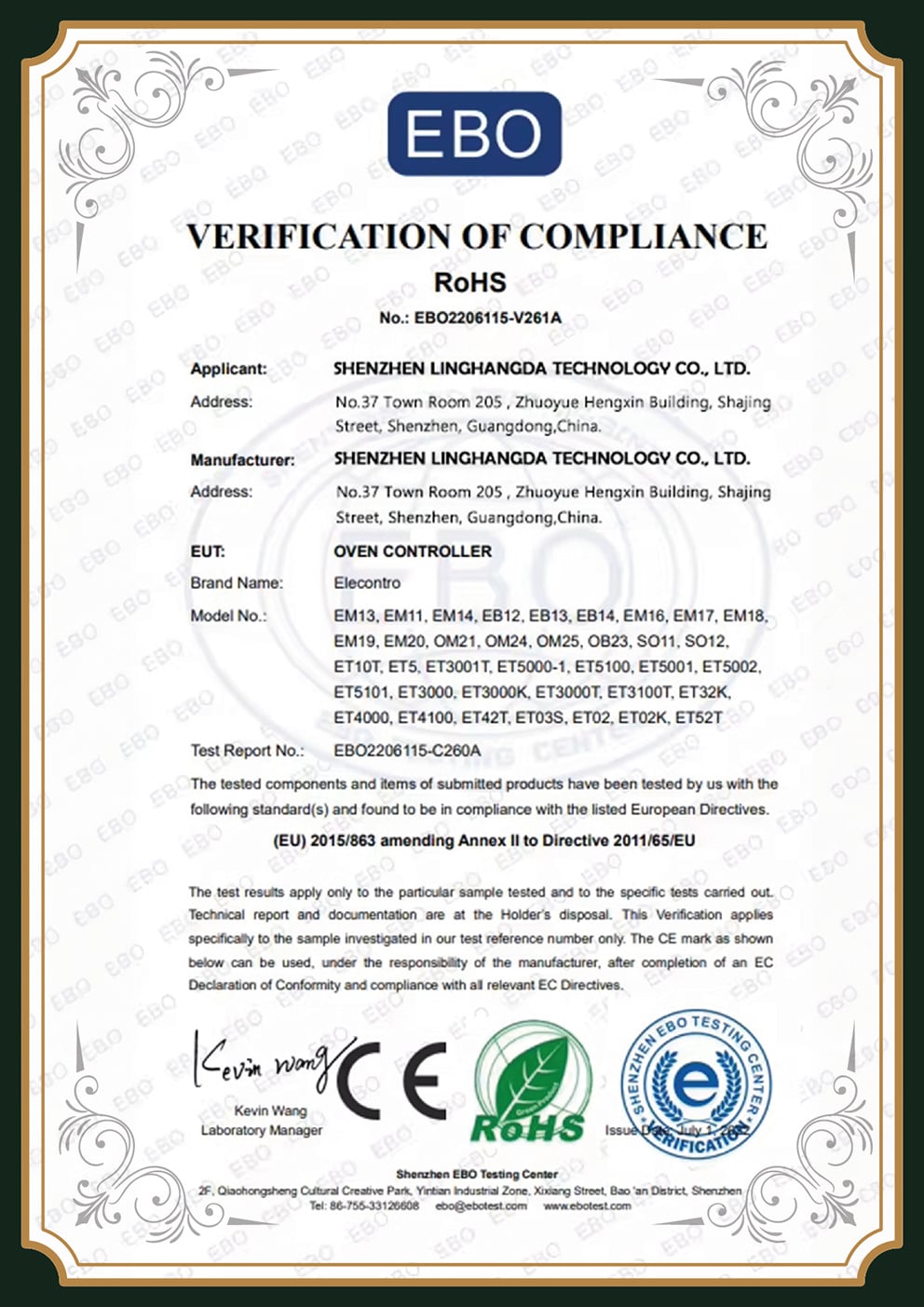
The most important factor to investigate with an international vendor; can he verify and substantiate, not merely claim compliance with specifications, which could be empty marketing rhetoric? Instead, we offer our substantiated record of international compliance to all our drone component assembly clients.
IATF 16949Automotive-grade QMS
ISO 9001Quality management
ISO 14001Environmental
ULListed materials
CEEU conformity
RoHSHalogen-tested
Sadly, too many UAV program managers have fallen prey to the cheapest supplier claiming ISO 9001 who can’t produce documentation and a certificate under audit. Unfortunately, and perhaps unintuitive, these highest risks occur with discount offshore vendors because quality controls are often flimsy. We will provide the certification numbers with the certified board’s building class.
For those who need to satisfy standards such as that mandated by military (defense-grade), medical and beyond visual line-of-sight; we switch to a lower production rate of component placement, employ rigorous testing at various stages and follow strict protocols. Our procedures align perfectly with those used for the highest demanding technologies for IPC Class 3 built assemblies.
Standard Governance for Drone PCBs
IPC-6012 (rigid board)
Plating thickness, hole quality, dielectric performance of the bare board
IPC-A-600 / IPC-A-610
Bare-board and assembly acceptance; Class 3 = zero-defect, life-critical workmanship
IPC-2221 / IPC-2152
Trace width and current-carrying capacity design rules
FCC Part 15 (US EMC)
Electromagnetic compatibility for radio-frequency emissions
High-reliability soldering and assembly benchmarks
Substantiated Verification Records





Procurement Framework
Drone PCB Procurement Guide, MOQ, Lead Times & Cost Drivers
Our pricing and quality discipline is built on the ISO 9001 quality management framework, so the figure you approve reflects a controlled, repeatable process.
A claim of “15 days delivery”, as the phrase imply, may not encompass everything, for example, DFM, test and shipment readiness or just its line item on the floor and without context for your project these figures are unreliable; similarly with cheap offshore, although unit cost appears very low – this can quickly escalate due to shipping costs, testing and delays and the cost for your drone flight controller can skyrocket!
The fact is that, in practice, we’ll tell you the real time needed to deliver your board and quote to the specific cost factors influencing the price you and the firm quote for your specified board in real terms and cost in actual time as opposed to imaginary timelines.
The Drone PCB Cost-Driver Reference
Every cost driver here’s a trade-off, and we give you the honest version instead of one headline number that hides the compromises.
Layer count & HDI
More layers and microvia/HDI raise fabrication complexity
Material
FR-4 is the cost baseline; aluminum-core, Rogers and polyimide cost more
Copper weight
2 oz+ power copper adds process cost but is required for ESC/PDB zones
Board size & panel use
Larger boards and poor panelization reduce yield per panel
Assembly complexity
0201, fine-pitch BGA and double-sided builds add placement & test time
Test class
IPC Class 3 + X-Ray/ICT/function test add verification cost and reliability
Order volume
Prototype unit cost is far higher than volume; setup amortizes at scale
Procurement advisory, what to lock in before you order
Build time explained – we’ll walk you through the phases; DFM fabrication, assembly, and shipping – and explain in detail what you’re to expect from our factory – from a low of just 1 to a maximum of 15 days depending on the scope of services and quantity involved.
Scale your production quantity for the appropriate phase – the idea is that we use the same manufacturing lines to keep the costs down as the number of units increases.
For your next design project, always demand a ‘single-system’ commitment to prevent fragmentation and maintain end to end product quality and accountability.
Engineering Resources
Drone PCB Engineering Tools
Evaluate material properties, estimate production costs, and verify design-for-manufacturing (DFM) requirements using our dedicated drone PCB engineering utilities.
01
Drone PCB Material & Stack-up Selector
Configure layer counts, dielectric materials, and copper weights to optimize your UAV flight controller and power distribution boards.
Open Tool
02
Drone PCB Cost-Driver Index Estimator
Evaluate the pricing impact of HDI, test class, production volume, and specific material choices on your custom drone PCB build.
Launch Estimator
03
Drone PCB DFM / Quote-Readiness Checklist
Validate your engineering files, manufacturing specifications, and acceptance criteria to ensure a seamless transition to production.
View Checklist