✓ ISO 9001 Certified 16+ Yrs Exp 500,000 m²/yr EMS

Rigid-Flex PCB Manufacturer

Rigid-Flex PCB Manufacturer: 4–24 Layer Boards, IPC-6013 Class 3, DFM to Functional Test

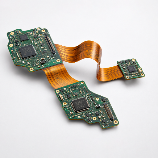
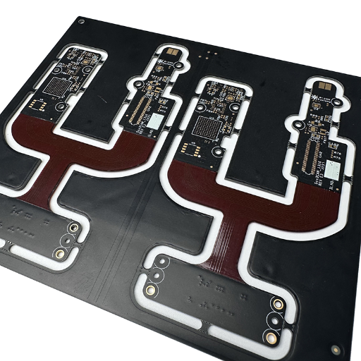
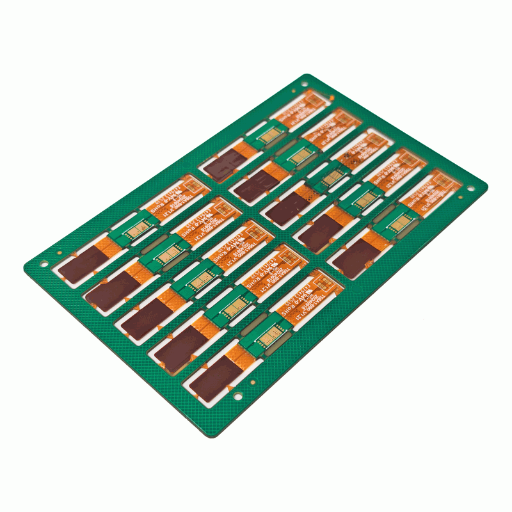
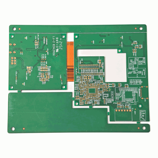
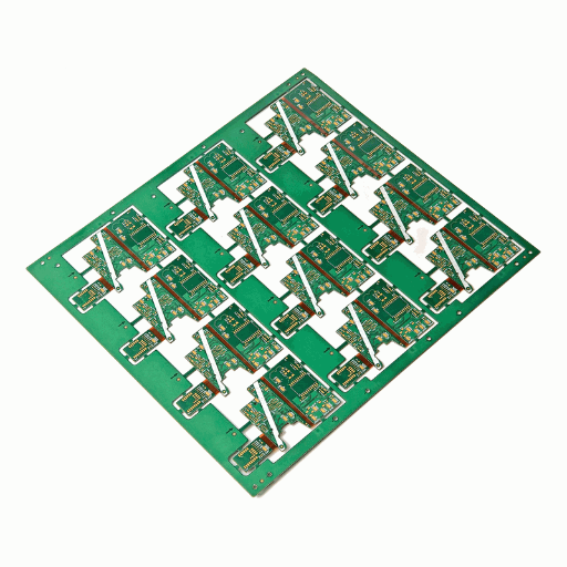
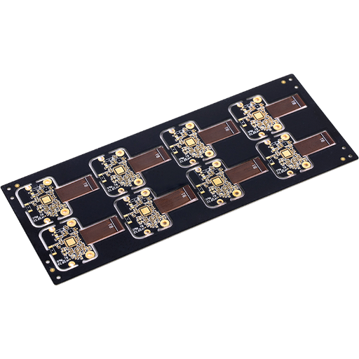
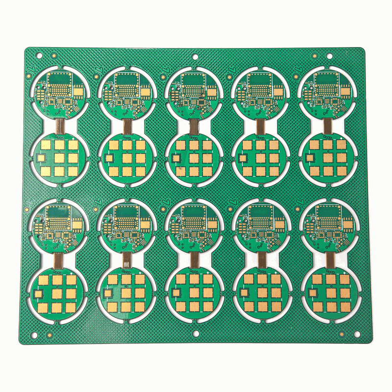
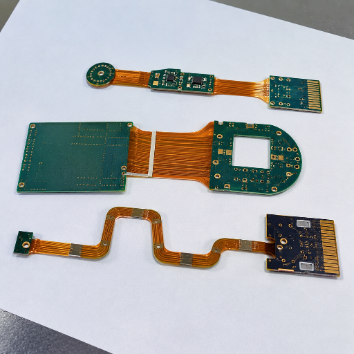
As a rigid-flex PCB manufacturer, PCBark builds boards that fuse rigid FR-4 sections and flexible polyimide sections into one part, an IPC-6013 Type 4 construction that bends into a 3D shape and removes the connectors and cables a separate rigid board would need. We run the full chain in-house: DFM, sourcing, fabrication, assembly, and 100% electrical test.

L
4–24 Layers(2–6 flex)
R
≥3× Min bend radius(Extreme)
C
100k+ CyclesDynamic bend
Z
±5% ToleranceImpedance control
T
0.050mmMin trace / space
E
100% E-test+ AOI + TDR
1/6
Rigid-Flex PCB 1
LAYER-01
Rigid-Flex PCB 2
LAYER-02
Rigid-Flex PCB 3
LAYER-03
Rigid-Flex PCB 4
LAYER-04
Rigid-Flex PCB 5
LAYER-05
Rigid-Flex PCB 6
LAYER-06

IPC-6013 Class 3

High-reliability build

IPC-2223

Flex/rigid-flex design

IPC-A-600

Acceptability standards

ISO 9001

Quality management

What a Rigid-Flex PCB Is, and When It Beats Rigid Boards Plus Cables

A rigid-flex PCB is a single circuit board that laminates rigid FR-4 sections and flexible polyimide sections together with plated through-holes connecting them, classified as IPC-6013 Type 4. It carries components on the rigid sections and bends or folds along the flex sections, so it replaces the board-to-board connectors and ribbon cables that a multi-board rigid assembly needs.

Eliminating Failure Modes

Pull the cables out of a tight enclosure and you remove the parts that fail first. In a board-plus-cable assembly, connector contacts and cable flex points are the joints that fret, crack, and intermittently open under vibration. By fusing rigid and flexible layers into one printed circuit board, a rigid-flex design folds the interconnect into the copper itself, so the signal path that used to cross two crimp terminals and a cable now run as one continuous etched trace that can withstand far more bending. Eliminating the need for connectors is the real reason aerospace and medical teams reach for it, not elegance, but the simple fact that every connector you delete is a failure mode you delete.

3D Packaging & Reliability

This board type earns its place when packaging is 3D and reliability is non-negotiable: a camera module that folds two rigid boards against a lens barrel, a hearing aid that wraps a battery, an avionics stack that has to survive launch vibration. There’s also an honest answer to a different question, when not to use it. If your design only mounts components on one side and you simply need a flat board to bend once during assembly, a flex PCB or a single-layer flexible circuit with a bonded stiffener is usually cheaper than full rigid-flex and does the same job. Expect us to say so during DFM rather than upsell you a Type 4 stackup you don’t need. That’s the honest trade-off we lay out up front.

A Different Tool

So a rigid-flex circuit board isn’t a premium version of rigid PCBs, it’s a different tool. Combining flexible and rigid construction trades a higher piece price for fewer parts, a smaller envelope, and a continuous interconnect. What follows shows exactly what we can build across flex and rigid-flex PCBs, how we keep the rigid-to-flex transition from cracking, and where the cost line actually sits once you count the system instead of the bare board.

Bridging the Gap

Rigid-flex PCB technology bridges the two basic types of PCBs, fully rigid and fully flexible. Rigid-flex printed circuit boards earn their advantages over traditional rigid boards by using a combination of rigid and flexible materials in a single stack. Where traditional PCBs rely on cables to reach a moving part, rigid and flexible PCBs use designs that can bend into the desired shape, because the flexible sections can withstand repeated flexing without mechanical failure. That spatial efficiency, plus the heat dissipation gained by spreading copper across more board area, is why engineers choose rigid-flex over separate rigid circuit boards for compact, high-vibration products. On a quote or a forum thread you’ll also see these called a rigid flex board, a flex rigid pcb, rigid flex circuit boards, or a rigid flexible pcb, all the same Type 4 construction.
PCBark Rigid-Flex PCB Build Envelope, Standard, Advanced & Extreme

Most rigid-flex manufacturer pages give you one flat capability list. Ours is banded into three classes so you can match your design to the right manufacturing process the moment you read it, and so procurement can scope an RFQ for flex and rigid-flex PCBs without a phone call.

Every value below come from our own process-capability sheet, not a marketing round-number. The Standard column is what we run at production volume with comfortable yield; Advanced is high-density work with HDI structures; Extreme is the high-layer, high-reliability envelope for aerospace and implantable programs. Read it as a decision tool: pick the tightest column your design actually needs, because each step toward Extreme adds cost and lead time.

PCBark Rigid-Flex PCB Build Envelope Classes
Parameter Standard Advanced Extreme
Total layers 4–8 6–16 24+
Flex layer count 1–2 2–4 6
Rigid layer count 2–6 4–12 20+
Base material FR-4 + Polyimide High-Tg FR-4 + PI High-speed material + PI hybrid
Flexible material PI / Polyimide PI + adhesiveless High-reliability flexible film
Rigid area thickness 0.6–1.6 mm 0.4–2.4 mm 3.2 mm
Flex area thickness 0.08–0.20 mm 0.05–0.25 mm Project-based
Copper thickness 0.5–1 oz 0.5–2 oz 3 oz
Parameter Standard Advanced Extreme
Min trace / space 0.10 / 0.10 mm 0.075 / 0.075 mm 0.050 / 0.050 mm
Min mechanical hole 0.25 mm 0.20 mm 0.15 mm
Min laser via 0.10 mm 0.075 mm 0.050 mm
Blind & buried vias Available HDI rigid-flex Multi-step HDI
Min bend radius ≥10× flex thickness ≥6× ≥3×
Dynamic bend cycles 1,000+ 10,000+ 100,000+
Surface finish ENIG, OSP ENIG, ENEPIG, Imm. Silver ENEPIG, Hard Gold
Stiffener material PI, FR-4 PI, FR-4, stainless Aluminum, steel, custom
Coverlay Yellow, black + white Custom colors
Impedance control ±10% ±8% ±5%
Max board size 250 × 400 mm 400 × 500 mm 500 × 600 mm
Testing 100% E-test AOI + flying probe + impedance AOI + E-test + TDR + reliability
Source: PCBark rigid-flex process-capability data. Values are achievable minimums/maximums by class, confirmed per project at DFM. Advanced HDI build methods follow published processes such as US Patent US10772220B2.

How We Engineer the Rigid-to-Flex Transition So It Doesn’t Crack

Are rigid-flex PCBs automatically more reliable than a cable assembly? No. A rigid-flex board is only more reliable when the rigid-to-flex transition is designed and built correctly. A bad transition, a tight bend at the board edge, a via too close to the flex, or the wrong copper grain, cracks faster than a well-made cable. Here’s the honest version: reliability is engineered into the transition, not inherited from the technology, and we won’t claim otherwise.

The transition zone, also called the transition area, is where rigid meets flex, and it’s the single most-documented failure point in this technology, the place where designers get burned and where IPC-6013E added dedicated acceptance criteria in its 2021 revision. We treat it as the part of the board that earns the program. Here’s the cause behind the failure: bend the flex too sharply at the rigid edge and you put the outer copper into tension it was never sized for; the trace work-hardens, micro-cracks, and over thousands of cycles opens into the “tens of ohms to open circuit” symptom that shows up on forums as a mystery defect. The root cause is mechanical, so the fix is mechanical.

Our transition rules aren’t opinions, they’re how the board survives. Copper grain is the first lever: we specify rolled-annealed (RA) copper for any section that flexes repeatedly, because its elongated grain structure resists fatigue far better than electrodeposited (ED) copper, which we keep to static flex-to-install sections only. We hold the first bend at least 1.5 mm back from the rigid edge so the stress relaxes into the flex rather than concentrating at the lamination line, and we keep vias and plated holes out of the bend area entirely. Coverlay, not solder mask, protects the flex; an adhesive bead at the transition control resin flow so the layers don’t delaminate where they’re most stressed, a process detail recent patents (US10772220B2) are built around.

Designing rigid-flex PCBs starts with the layer stackup. The design process for rigid and flexible sections differs from circuit design on a purely rigid board, because the flexible sections can be challenging to balance against the rigid areas in a single rigid and flexible board. Critical design considerations, the appropriate bend radius, the flexibility of the substrate, and how the layers of rigid and flexible copper stack, get settled before fabrication, not discovered at first article.

The 10-6-3 Bend-Radius Rule and Flex Endurance Classes

Our bend-radius capability runs on a simple “10-6-3” framing keyed to soft-area thickness: Standard work holds a minimum bend radius of 10× the flex thickness for static or one-time installation bends; Advanced reaches 6×; and our Extreme class goes to 3× for the tightest folds. We pair that with a Flex Endurance Class, FEC A at 1,000+ cycles for occasional service access, FEC B at 10,000+ for periodic motion, and FEC C at 100,000+ cycles for continuous dynamic flexing such as a hinge or a moving printhead.

Engineering note, 10-6-3 vs the IPC-2223 minimum

Our 10-6-3 numbers describe a static / install / dynamic capability against flex thickness. They aren’t the same framing as the IPC-2223 standard, which sets conservative minimum bend radii by layer count, roughly 6× for single-sided flex, 12× for double-sided, and 24× for multilayer in static use, with dynamic applications often run at far larger radii (some references use up to 100× total thickness for continuous motion). We design to whichever rule is stricter for your stackup and validate the build with flex-endurance testing per the intent of IPC-TM-650 Method 2.4.3, rather than quoting a single round cycle number with no test behind it.

“The first thing we check on a rigid-flex layout is not the trace width, it is where the bend lands relative to the rigid edge and the via field. Move the bend 1.5 mm and switch the dynamic section to RA copper, and a board that would have failed at a few thousand cycles passes a hundred thousand. The transition is the whole job.”
PCBark Rigid-Flex Engineering Team
Failure mode at the transition Root cause How PCBark prevents it
Outer-layer trace cracking Bend radius below copper fatigue limit 10-6-3 radius rule + RA copper for dynamic flex
Permanent crease / kink Bend located at the rigid edge 1.5 mm bend keep-back from rigid section
Barrel / via cracking Plated holes inside the bend area 0.5 mm via keep-out from flex zone
Transition delamination Uncontrolled resin flow at lamination Adhesive bead + IPC-6013E transition criteria
Unbalanced-stackup warp Asymmetric copper distribution Balanced build / asymmetric blind-hole process

Rigid-Flex Stack-Up & Materials, Polyimide, Coverlay, Stiffeners

The stack-up is where a rigid-flex board is won or lost, because the flex section and the rigid section want different things. The flex layers are built on polyimide film, usually adhesiveless laminate for high-reliability work, since the adhesive layer in cheaper constructions is the part that delaminates under heat. The rigid sections use FR-4, or high-Tg FR-4 when assembly sees lead-free reflow, and we can run a high-speed material hybrid where signal integrity matters.

On the flex, coverlay replaces solder mask. This is the coverlay vs LPI question buyers ask about, much like the polyimide vs FR4 material choice: coverlay is a laminated polyimide film with a pre-cut opening, and it survives bending where liquid photo-imageable (LPI) solder mask would crack. We use coverlay across every dynamic flex section and reserve LPI for rigid areas only. Stiffeners go where the flex need local rigidity, under a connector or a component pad, in polyimide, FR-4, stainless steel, or aluminum depending on whether you need thickness, heat spreading, or grounding.

Read More
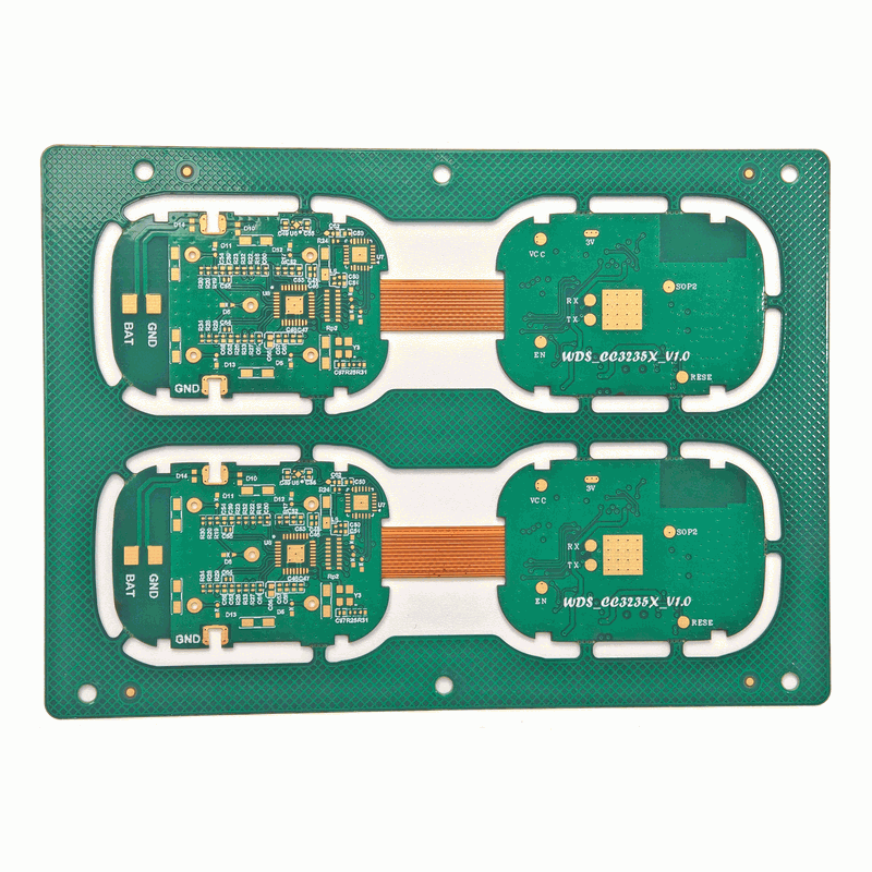
PCB Stack-Up Configuration

Stack-Up Choices That Change Cost and Reliability

01_

Adhesiveless polyimide for dynamic flex, better z-axis stability and bend life than adhesive-based film

02_

Surface finish: ENIG and OSP for Standard; ENEPIG and immersion silver for fine-pitch; hard gold for contact/edge-connector wear

03_

Prepreg and laminate selection balanced top-to-bottom to stop the board from warping after lamination, the unbalanced-stackup failure mode that dedicated asymmetric rigid-flex processes exist to solve

04_

Controlled impedance from ±10% down to ±5%, verified by TDR on the Extreme class

Material Selection is Also an Electronic Design Decision

that ties into our wider HDI PCB and PCB assembly work, because the stack-up you choose for the flexible board determines whether fine-pitch BGAs and their solder joints can sit on the rigid islands. These board technologies interact during reflow soldering, so we settle them early in the manufacturing process, before you release the design, not after the first build fail. The assembly process for rigid-flex PCBs carries its own handling rules, and HDI flex PCBs add laser-drilled microvias that a simpler rigid and flexible board wouldn’t need.

What Does A Rigid-Flex PCB Really Cost? Board Price Vs System TCO

Why are rigid-flex PCBs more expensive?

At the bare-board level a rigid-flex PCB can run several times the price of an equivalent rigid board, one industry whitepaper puts it near 7× — because it adds layers, tighter tolerances, polyimide materials, and a more skilled build. The number that matter for a buying decision is the system cost, which often moves the other way once connectors, cables, assembly labor, and test cycles are counted.

Let’s be straight about the sticker shock, because every first-time rigid-flex buyer feels it. Cost is a big factor, and U.S. buyers who price flex for the first time tend to compare it against rigid and wince; flex circuits do run more than a comparable rigid board, worst of all at prototype quantities where the tooling spreads across a handful of pieces. Pretending otherwise costs trust. The honest trade-off is straightforward: you pay a premium on the board to take cost out of the whole system. The honest case for rigid-flex isn’t that the board is cheap, it’s that the board is one line on a bill of materials that gets shorter everywhere else.

~7× Board, Lower System

A rigid-flex board carries roughly a 7× bare-board premium over rigid (Minco), yet the system total cost of ownership frequently lands lower once you remove the connectors, cables, assembly labor, and multi-stage test that a board-plus-cable design needs. Weight savings of 60%+ are common when one rigid-flex board replaces several rigid PCBs and their cabling.

Sources: Minco rigid-flex cost whitepaper; Epec cost-benefit analysis. Directional figures — request a quote for your build.
Here’s the boundary drawn explicitly, because procurement teams lose faith in any page that only argues one side:
Cost Line Board + Cable + Connectors Rigid-Flex PCB
Bare board piece price Lower (baseline) Higher (up to ~7×)
Connectors & cable assemblies Added per interconnect Eliminated
Production lines Multiple (board, cable, connector) Single production line
Test cycles Board + joints + cable, multi-stage Single 100% E-test run
Assembly & installation labor Manual routing, install-error risk Folds one way only, low error
Weight / enclosure size Baseline Up to 60%+ lighter, smaller envelope

The crossover depend on volume and how many interconnects you’re deleting. Two rigid boards joined by one cable rarely justify rigid-flex on cost alone, you’re buying reliability there, the same connector-deleting topology described in US Patent US12382583B2. Replace four boards and a wiring loom in a vibrating enclosure, and the system math usually favors rigid-flex before you even price in field returns. We’ll model that line with you instead of asserting a percentage we can’t source.

Rigid-Flex PCB Applications, Medical, Aerospace, Automotive & Wearables

Rigid-flex started as a spacecraft technology and has spread to anything small, moving, or mission-critical. The rigid-flex market sat around $4.2 billion in 2024 and is tracking toward roughly $6.3 billion by 2030 (Strategic Market Research) — growth driven by exactly the products that can’t tolerate a connector. The common thread across these markets is survival in harsh environments, vibration, thermal cycling, and electromagnetic interference (EMI) — where a folded board with corrosion-resistant finishes and built-in thermal management outlasts a cabled build. Our three capability classes map cleanly onto where the technology is used:


Medical electronics

Medical electronics

Medical electronics

pacemakers, hearing aids, ultrasound probes, and expandable catheters where the board has to fold into the body or a sealed shell. Recent patents put rigid-flex inside ultrasound energizers (US11903118B2) and interventional catheters (US10201311B2); these are the high-reliability, Class-3 builds for implantable medical devices.

Aerospace & defense

Aerospace & defense

Aerospace & defense

avionics stacks, satellites, and guided systems that have to pass launch vibration with no intermittent opens. IPC’s military-applications data shows adhesiveless rigid-flex passing 2,000+ flex cycles with no barrel cracking.

Automotive electronics

Automotive electronics

Automotive electronics

camera modules, LiDAR, and instrument clusters. A current two-board rigid-flex camera patent (US12382583B2) is exactly the topology we build, two rigid islands joined by a flex.

Wearables & consumer

Wearables & consumer

Wearables & consumer

smartwatches, earbuds, and folding cameras where every cubic millimeter count, the flex wraps the battery, and the same approach scales across the automotive industry and other smart devices.

For the highest-temperature or highest-frequency corners of these markets, rigid-flex often shares a program with our ceramic PCB and Rogers PCB lines, we keep those decisions under one roof so the interconnect and the substrate are designed together.

Why Aerospace & Medical Buyers Can Trust a Rigid-Flex PCB Manufacturer They Haven’t Used
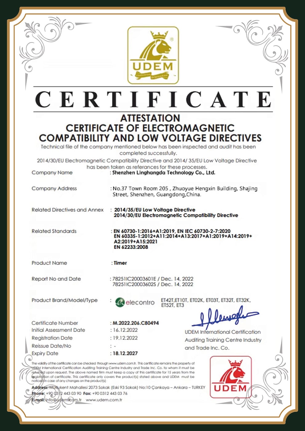
A new supplier earns trust through verifiable standards, not brand age.

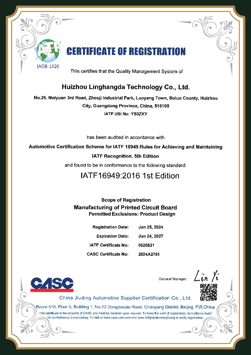
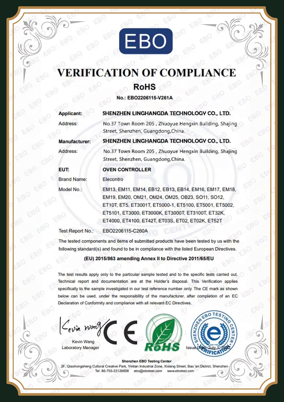
PCBark builds to IPC-6013 Class 3, the high-reliability class many government programs accept as a commercial equivalent to MIL-PRF-31032, and proves every board with a 100% test stack. The certificate and the test data travel with the order, so you audit the work rather than the logo.

We know the objection, because it’s the right one to have: why hand an aerospace or implantable program to a manufacturer you haven’t run before, when Sierra and TTM sit in your existing supply base? The answer isn’t a promise. It’s IPC-6013 Class 3 build acceptance, IPC-2223 design rules, and IPC-A-600 visual criteria applied to every panel, the same standards your incumbent is held to. Class 3 is the high-reliability tier where end-use failure isn’t an option, and many defense and medical buyers treat it as the COTS path to MIL-PRF-31032 expectations, the reliability class behind implantable designs such as US Patent US11903118B2.

Then we prove it instead of claiming it. Every board see 100% electrical test; AOI and flying-probe catch what the eye misses; TDR confirms the controlled impedance on the Extreme class. First-article inspection data and the Class-3 certificate ship with the order. That’s the substance behind 16+ years of EMS and a 500,000 m²/yr facility, not a slogan, a paper trail you can hold.

IPC-6013 Class 3

High-reliability acceptance

100% E-test

Every board

AOI + Flying Probe

Automated inspection

TDR Impedance

±5% verified

First-Article Data

Ships with order

× Enlarged Certificate
Rigid-Flex Manufacturing Facility

Rigid-Flex PCB Procurement, Quote, Lead Time & DFM Partnership

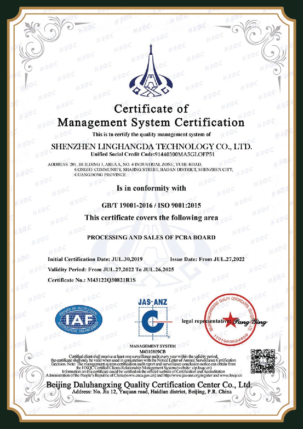
Buyers who have shipped rigid-flex give newcomers one piece of advice over and over: pick the vendor you can have the most back-and-forth with on DFM. This board type fails in design review, not in fabrication, so the supplier relationship is the risk control. As a turnkey rigid-flex PCB manufacturer, we run DFM, sourcing, fabrication, assembly, and functional test under one roof, there is no handoff where a flex-specific design rule gets lost between a board house and a separate assembler, and the whole line runs under our ISO 9001 quality system. Good rigid-flex PCB design lives or dies in that DFM conversation, because printed circuit board manufacturing for a Type 4 stackup follows flex-specific rules a generic PCB design review will miss.

What Drives Your Rigid-Flex Quote

Pricing on rigid-flex is set by a handful of factors more than by a simple area calculation. Knowing them helps you scope a design before you ask for a number:

01_

Layer count and flex-layer count, the biggest single driver

02_

Reliability class (Class 2 vs Class 3 adds roughly 20–40% per IPC-6013 acceptance)

03_

HDI features, laser vias, blind/buried structures, fine-pitch BGA

04_

Surface finish, ENIG vs ENEPIG vs hard gold

05_

Quantity, the premium is worst at prototype volume and improves at production

Send us a stackup, a Gerber, or even a hand sketch and we return a DFM review with the build class, the cost drivers we see, and a quotation against your parameters. We would rather flag a transition-zone problem or recommend a cheaper flex-with-stiffener build at quote time than discover it at first article. Request a quote and we'll start the DFM conversation, not just send a number.

Request a Quote

Rigid-Flex PCB Engineering & TCO Tools

01

Rigid-Flex PCB Build-Class Selector

Match your design to PCBark's Standard, Advanced, or Extreme build envelope.

Access Tool
02

Rigid-Flex Bend-Radius & Endurance Calculator

PCBark's 10-6-3 capability vs the IPC-2223 layer-count minimum — designed to the stricter rule.

Access Calculator
03

Rigid-Flex vs Board + Cable: System-TCO Direction

The bare board costs more. This shows where the system cost moves — directional, no quote required.

View Direction

Rigid-Flex PCB FAQ

An FPC (flexible printed circuit) is all flex, a thin polyimide circuit with no rigid sections. A rigid-flex PCB combines rigid FR-4 sections and flex sections in one laminated board with plated through-holes connecting them. The FFC vs FPC distinction matters too: an FFC is a flat flexible cable, not an etched circuit. Use an FPC when the whole circuit bends; use rigid-flex when you need rigid islands for components plus flex interconnects between them.

It can be, but only with correct design. Removing connectors removes failure points, which is why rigid-flex dominates aerospace and medical, including implantable designs like US Patent US10201311B2. A poorly designed transition zone, though, fails faster than a well-built cable assembly. Reliability shows up when the bend radius, copper type, and via keep-out are right, it isn't automatic.

The bare board adds layers, polyimide materials, tighter tolerances, and a more skilled build, so it can run several times the price of a rigid board, with the worst premium at prototype quantities. System cost usually drops, because rigid-flex deletes connectors, cables, extra production lines, and multi-stage testing.

Our capability run from 10× the flex thickness for static bends down to 3× for the tightest folds. The IPC-2223 standard sets conservative minimums by layer count, about 6× single-sided, 12× double-sided, 24× multilayer for static use, and larger radii for continuous dynamic flexing. We design to the stricter rule for your stackup.

Coverlay is a laminated polyimide film with pre-cut openings that protects the flex circuit. It bends without cracking, which liquid photo-imageable (LPI) solder mask can't. We use coverlay on all flex sections and keep LPI solder mask to the rigid areas.

IPC-6013 defines three classes. Class 1 is general electronics, Class 2 is dedicated-service, and Class 3 is high-reliability where failure isn't acceptable, aerospace, medical, and defense. Class 3 adds tighter acceptance on the transition zone and costs roughly 20–40% more than Class 2. Most rigid-flex programs specify Class 2 or Class 3.

Yes. PCBark is a turnkey EMS provider: DFM, material sourcing, fabrication, SMT assembly, and functional test in one place. Keeping fabrication and assembly together matters for rigid-flex because flex-specific handling and bend rules carry through to the assembly line without a vendor handoff.

Rolled-annealed (RA) copper for any section that flexes repeatedly, because its elongated grain structure resists fatigue. Electrodeposited (ED) copper is used only for static or flex-to-install sections. Choosing the wrong copper for a dynamic application is one of the most common causes of early flex failure.