Get in touch with PCBark Company

Prototype PCB Assembly
Prototype PCB Assembly, From a Single Proto Board to Volume Production
Build, test, and scale your design on the same IPC-A-610 Class 3-capable SMT lines, with a real engineering DFM review on every job, transparent quick-turn lead times, and no minimum order. One partner from your first 5-board proto to your first 50,000-unit run.
Boards shipped into:
consumer electronics, medical, automotive, IoT, robotics, industrial, aerospace, drones
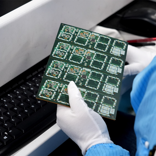
8
SMT lines
9M
placements / day
0201
min component
24h
quick-turn (1–10 pcs)
No MOQ
1 board and up
IPC Class 3
capable, ISO 9001/UL
Smart DFM Ready
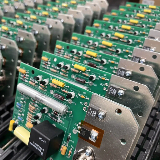
Why Your Prototype PCB Assembly Partner Decides Your Time-to-Market
Prototype PCB assembly is the step where a Gerber file and a bill of materials becomes a physical, testable board—and it’s where most schedule slips are quietly created. The trap is treating price and lead time as if they were capabilities. They aren’t. A shop can quote the cheapest price and the fastest turnaround precisely because it runs a high-volume, low-touch operation that processes files automatically and minimizes engineering engagement.
According to a 2026 survey of 439 OEM engineering and procurement professionals, 46% estimate that a single change made after the design freeze exceeds $50,000. A footprint error that an automated portal waves through becomes a re-spin, a re-qualification cycle, and weeks of slipped revenue.
Turnkey Timeline
Proactive DFM Review
First-time footprint & clearance verification.
Component Sourcing
Transparent path to eliminate long lead times.
SMT & Functional Test
8 certified lines for reliable agile scaling.
The Foundation
“PCBark closes that gap with a different model: a turnkey path run by an agile engineering team rather than an automated file queue. The same lines build your first 5-board prototype and your 50,000-unit production run.”
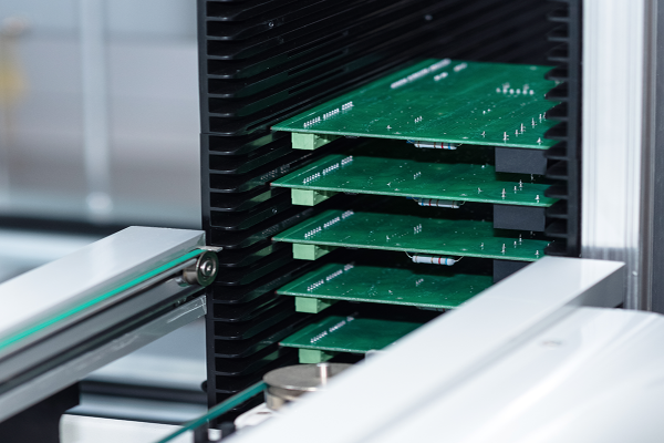
Quick-Turn Lead Times by Quantity, the PCBark Prototype-to-Production Scale Matrix
Quantity (PCS)
Expedited
Standard quick-turn
Stage
1–10
24 hours
48–72 hours
Design validation
11–50
48 hours
3–5 days
Iteration / EVT
51–100
3 days
5–7 days
Low-volume / DVT
100–500
5 days
7–10 days
Pilot / pre-production
Note: industry definitions for quantity tiers that inform our commitment: prototype: 1 to 25 boards (to validate a design) / low volume: 10 to 500 boards / bridge quantity: 50 to 1,000 / production: 1,000+ boards.
Inside Our Prototype Assembly Process, DFM → Build → Test
The single most important thing a prototype assembler does is also the thing buyers most often can’t see on a quote: the design-for-manufacturing review. A surface-level, automated DFM report flags only the obvious rule violations any tool catches. A genuine engineering DFM review reads design intent, and that distinction is decisive, because by one practitioner estimate approximately 94% of assembly data sets arrive with at least one error.
“Assuming the manufacturer will figure it out” is how a missed clearance become a copper sliver bridging power to ground, and a $500 fix at prototype becomes a five-figure problem at production.
Every PCBark job starts with that human review. Our front-end engineers check footprint-to-part match, annular ring against drill wander, trace and space against the etch process, and solder-mask web before a board is tooled, the failure modes that pass first power-up and then fail after thermal cycling. The 3W rule for trace spacing, IPC-2221 clearance baselines, and impedance targets are verified against both the standard and our line’s real capability, not just a generic design-rule check.
The PCBark DFM Readiness Checklist
What a real review verifies before tooling. Our engineers check every one on each prototype:
- Footprint-to-part match, every reference designator maps to the BOM part it will receive
- Annular ring vs. drill wander, pads hold a reliable plated-through-hole barrel
- Trace / space against the etch process and copper weight, no bridging or mask slivers
- Solder-mask web and clearance per IPC-2221
- Controlled-impedance and stackup definition present (no undefined targets)
- Fine-pitch and BGA land geometry buildable on our lines (down to 0201)
- Panelization and fiducials for automated placement
- Component availability and authorized-source confirmation before tooling
Build and inspection stack
Real-time data-driven line control & technical deployment:
After paste print, solder-paste inspection (SPI) verifies deposit volume before a single component is placed. Post-reflow, automated optical inspection (AOI) scans every board for placement and solder defects, not as an opt-in upgrade, but as standard. Hidden joints under BGAs and QFNs are confirmed by 3D X-ray inspection; electrical behavior is verified by in-circuit test (ICT), flying probe for low-volume and prototype runs, and customer-defined functional test where a jig is supplied. As one industry guide put it bluntly, “Assembly houses that don’t employ AOI put their customers at risk” — which is the honest reason we run it on 100% of boards rather than as a paid upgrade. Industry practice is moving toward exactly this kind of closed-loop, data-driven line: a 2024 EMS patent from a major contract manufacturer describes linking printer, SPI, pick-and-place, AOI, and reflow to a single feedback engine (USPTO US20240248463A1, 2024), and a granted 2023 patent predicts SPI/AOI quality from design data before a board is built (US11825606B2). Our process control reflects the same principle, catch the defect at the station that caused it.
“Most of the boards that come back to us at production ramp are not failing because of the components, they’re failing because the prototype was built fast and clean on a process that never matched the production line. We test 100% of prototype boards through AOI and X-ray for one reason: the prototype is the only chance to find a problem before it ships a thousand times.”
Industry Insight
Offshore Prototype Assembly Done Right, China Cost, IPC Class-3 Quality
Two assumptions deserve to be challenged head-on. The first: that the lowest piece price wins. On a true total-cost-of-ownership basis, a board bought at roughly half the domestic piece price has been shown to end up 18.5% more expensive once freight, duties, inventory carrying, communication overhead, and rework are counted, and about 60% more over a five-year horizon.
The second: that “Made in China” automatically means a tariff penalty that erases the savings. In reality the bare board is only about 8–12% of a finished product’s bill of materials, so even a 10% tariff on the board works out to roughly a 1% impact on end-product cost , and 2- and 4-layer rigid PCBs from China currently carry a Section 301 exclusion (9903.88.69) extended through November 2026. Rates change month to month; we quote landed cost transparently and recommend verifying the live HTS rate at order time.
$50,000+
The average cost of a single post-design-freeze change reported by 46% of surveyed OEMs. A real prototype DFM review and a production-grade test stack exist to catch the footprint, clearance, and sourcing problems that force these changes.
Source: Accuris Intelligence Survey, March 2026.
So the honest question is not “offshore or domestic” but “which offshore” — and the honest trade-off is between a certified partner and a low-touch broker that quotes the same board. That gap is exactly where prototype projects are won or lost.
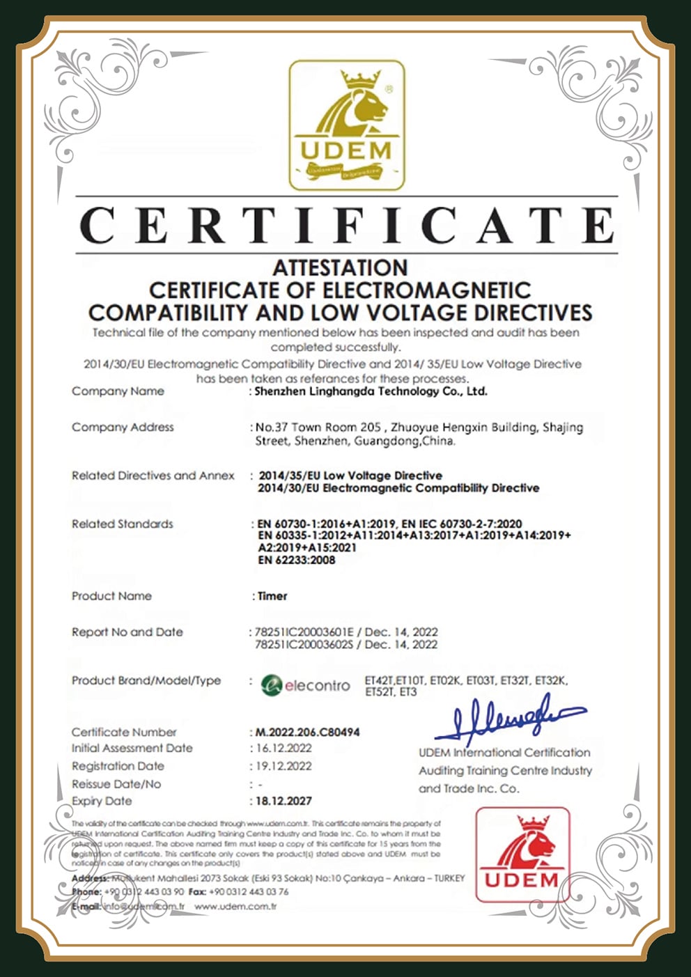
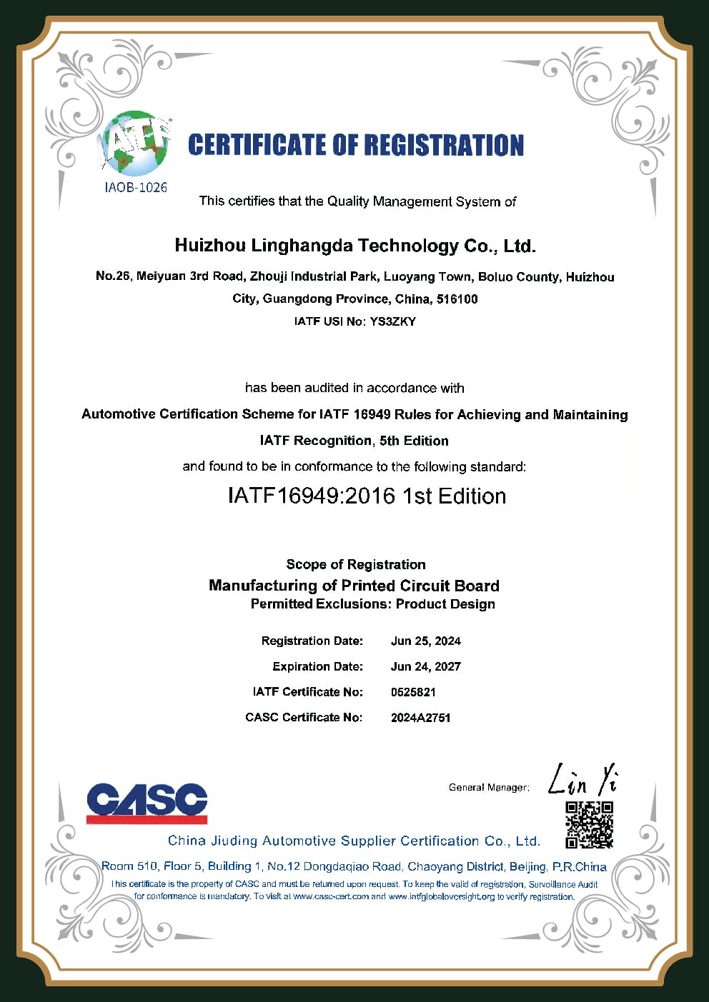
Certifications & Quality Systems
Certification is a floor, not a finish line, a credential tells you the minimum is met, not how far above it a supplier operate. We treat it that way. PCBark builds to IPC-A-610 Class 2 for consumer and industrial product and Class 3 for medical, automotive, aerospace, and mission-critical assemblies, where, as IPC’s own standards director frames it, “continued high performance or performance-on-demand is critical… and the product must function when required.” Soldering follows IPC J-STD-001, and the line runs under an ISO 9001-certified quality system, so every board carries batch and serial traceability from component lot to final test.
Trust at the Component Level
Trust at the component level is just as deliberate. Counterfeit and out-of-stock parts enter through unauthorized channels, and 2024 industry data logged a 25% year-over-year rise in suspect parts, with visual inspection now catching only about 60% of professional fakes. PCBark sources through authorized distributors, Digi-Key, Mouser, Arrow, so parts trace back to the original manufacturer, and a Certificate of Conformance with lot and date codes is available on request. If a part can only be found on the open market, we tell you, and we inspect accordingly rather than quietly substituting.
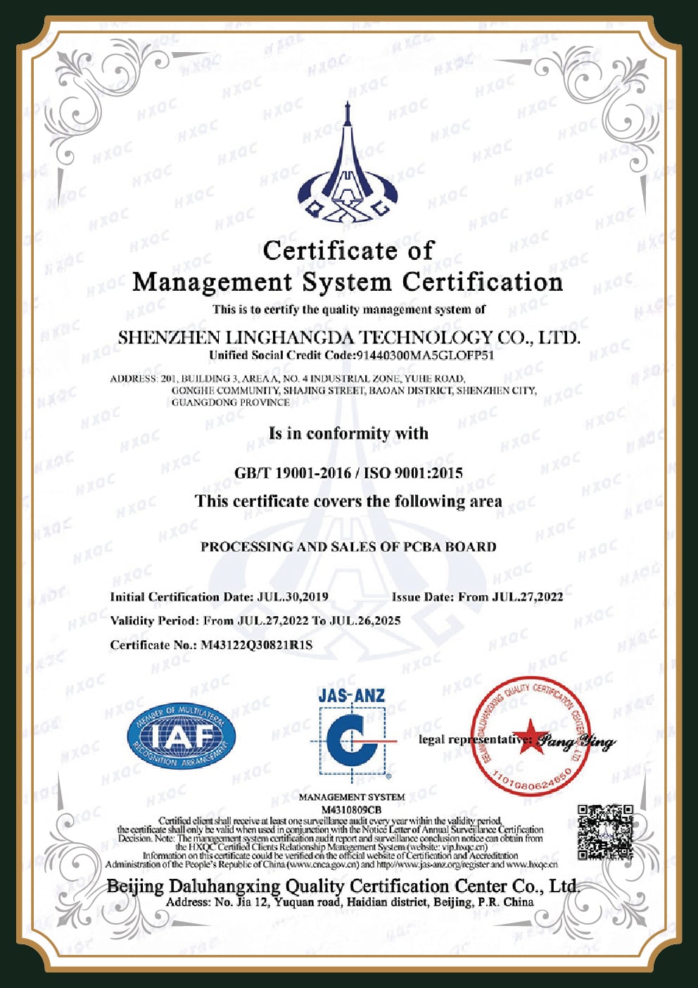
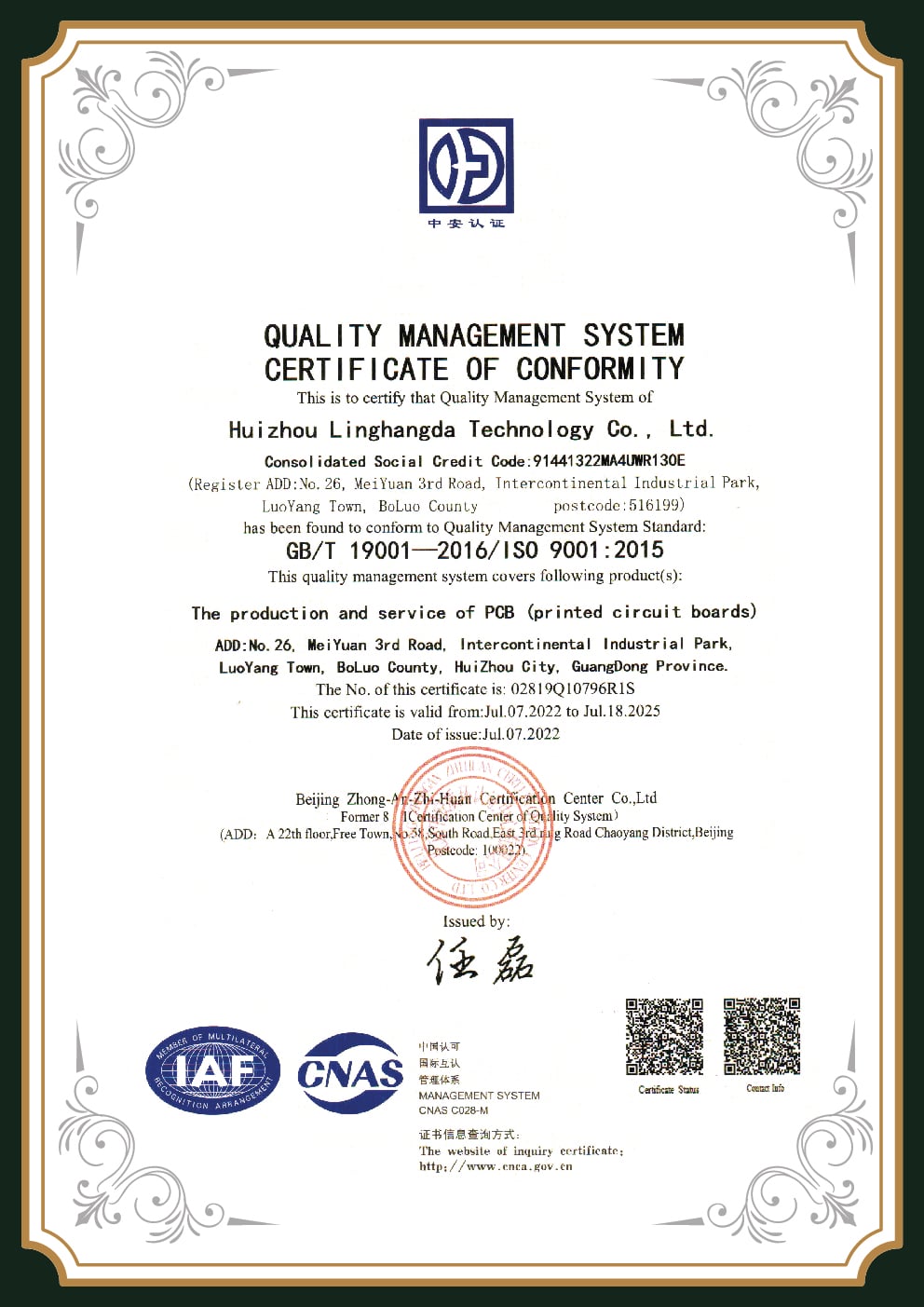
ISO 9001:2015
QMS · since 2011
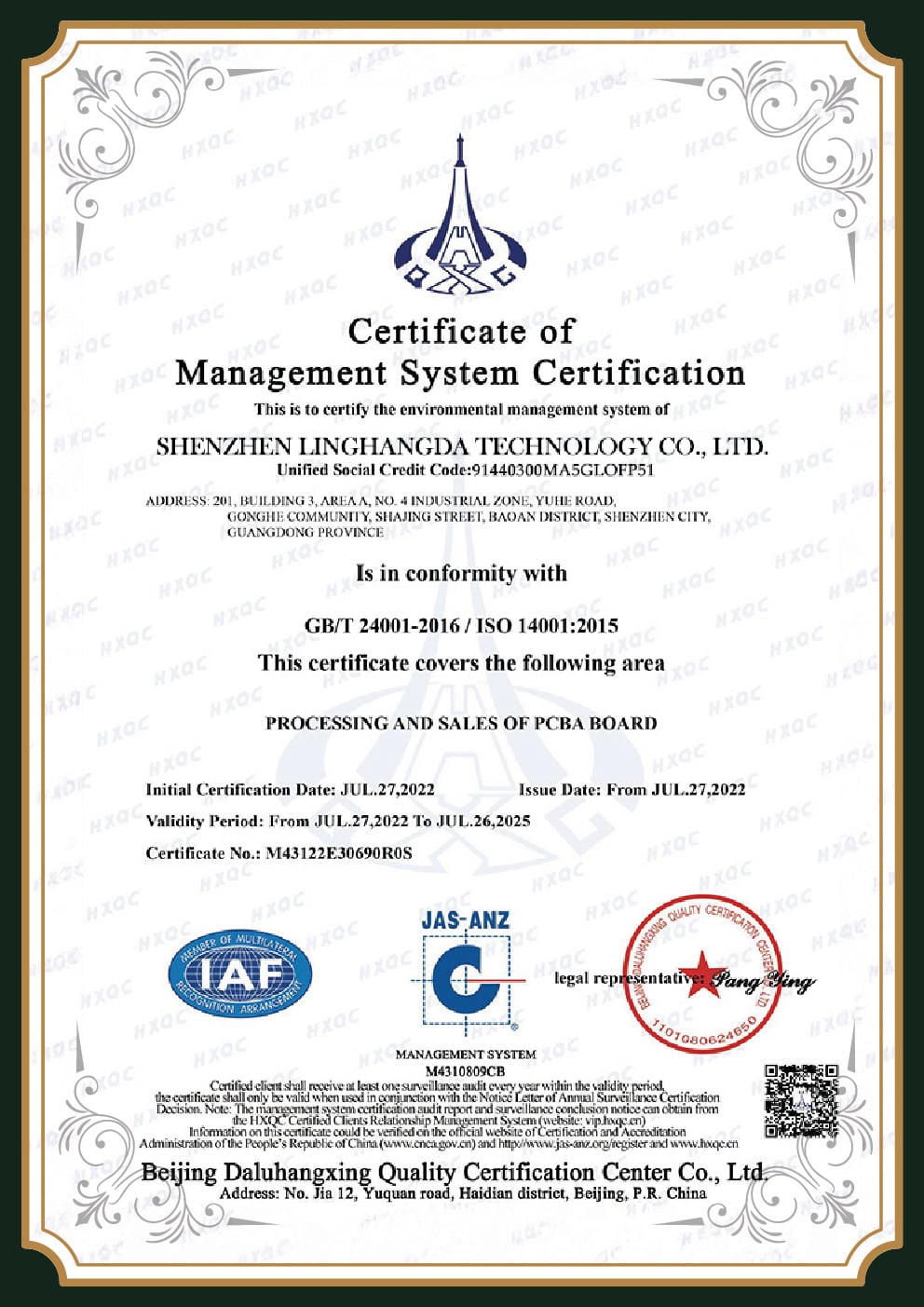
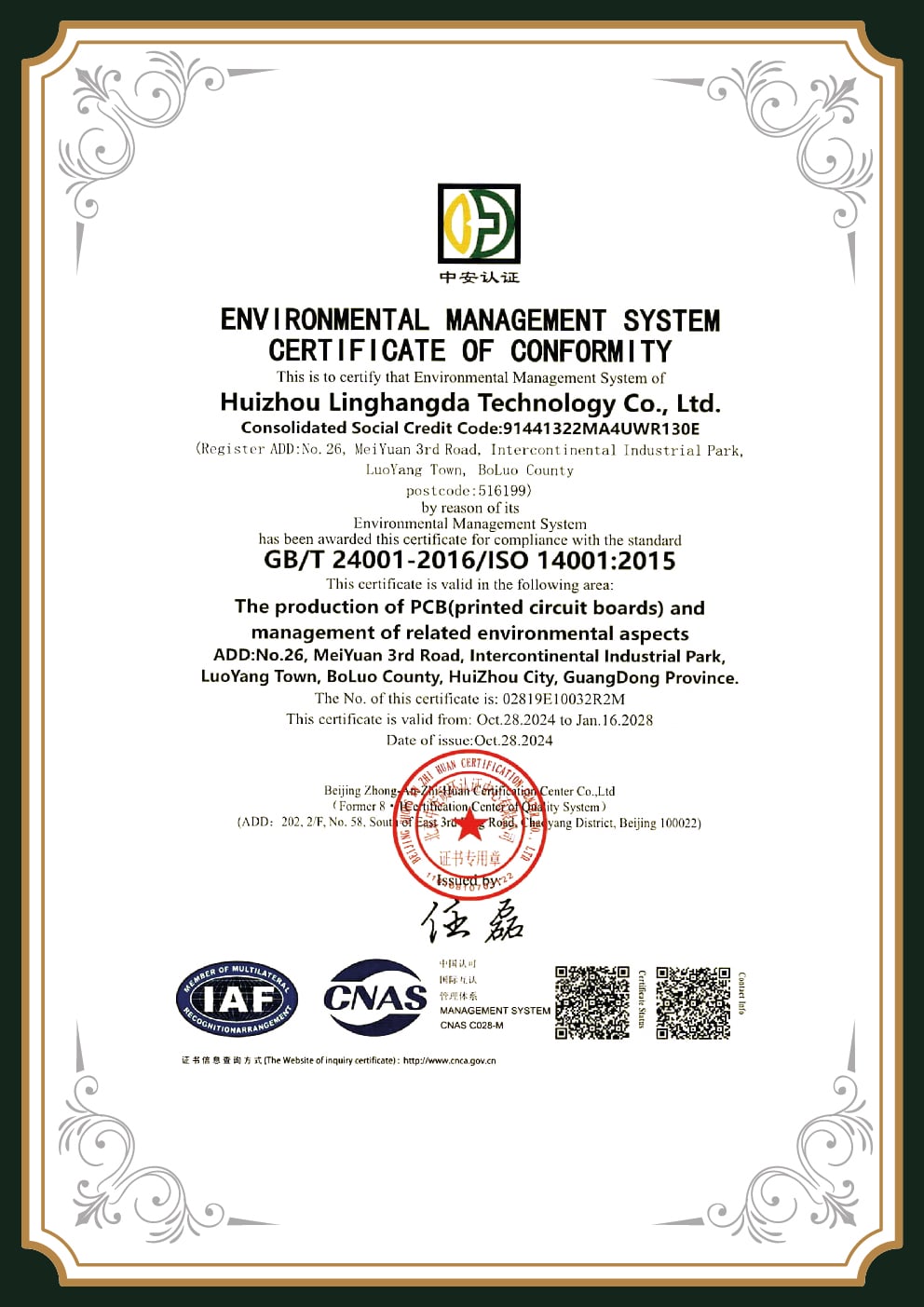
ISO 14001
Environmental · 2011
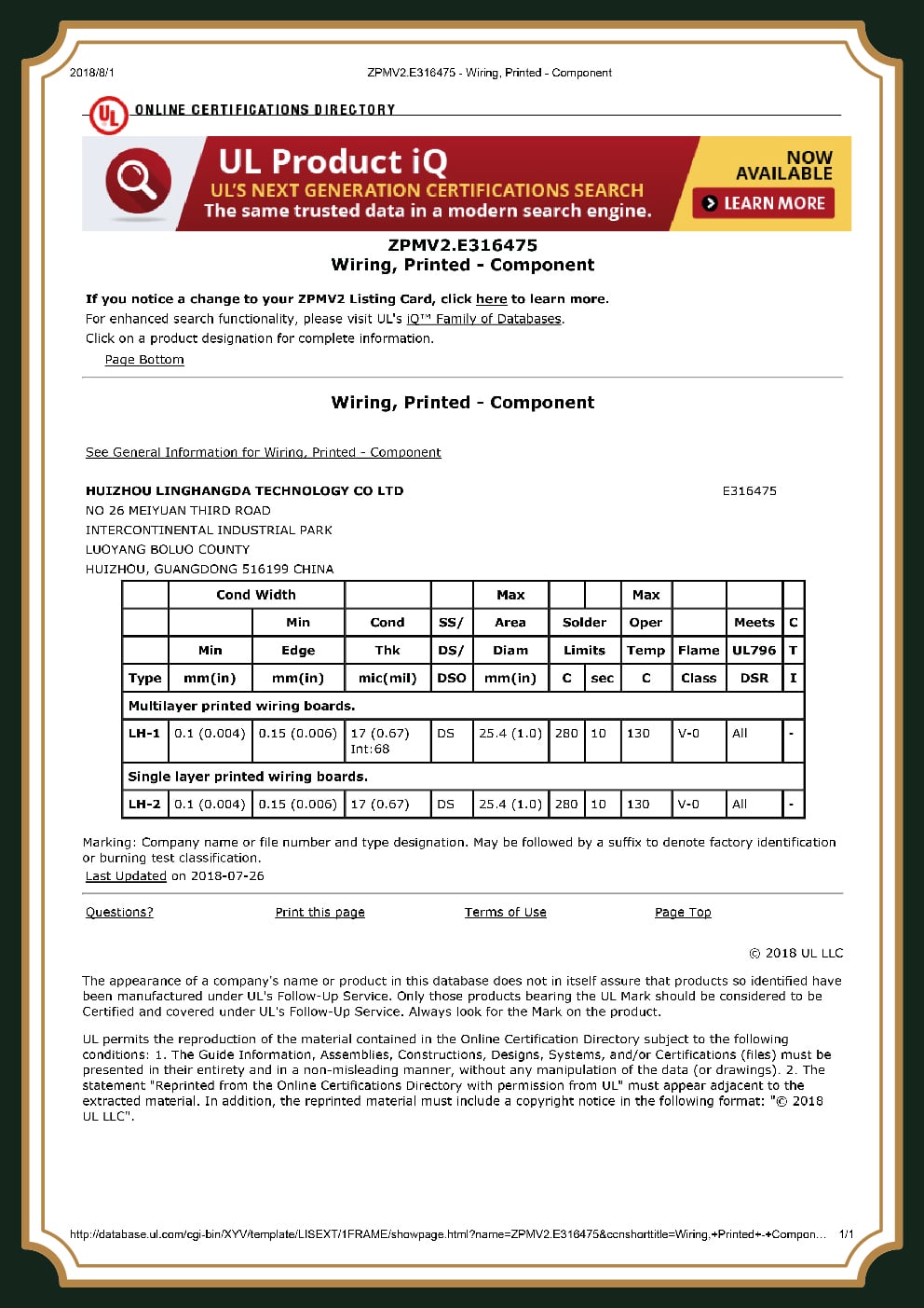
UL
Listed · since 2014
IPC-A-610
Class 2 & 3 capable
J-STD-001
Solder acceptance
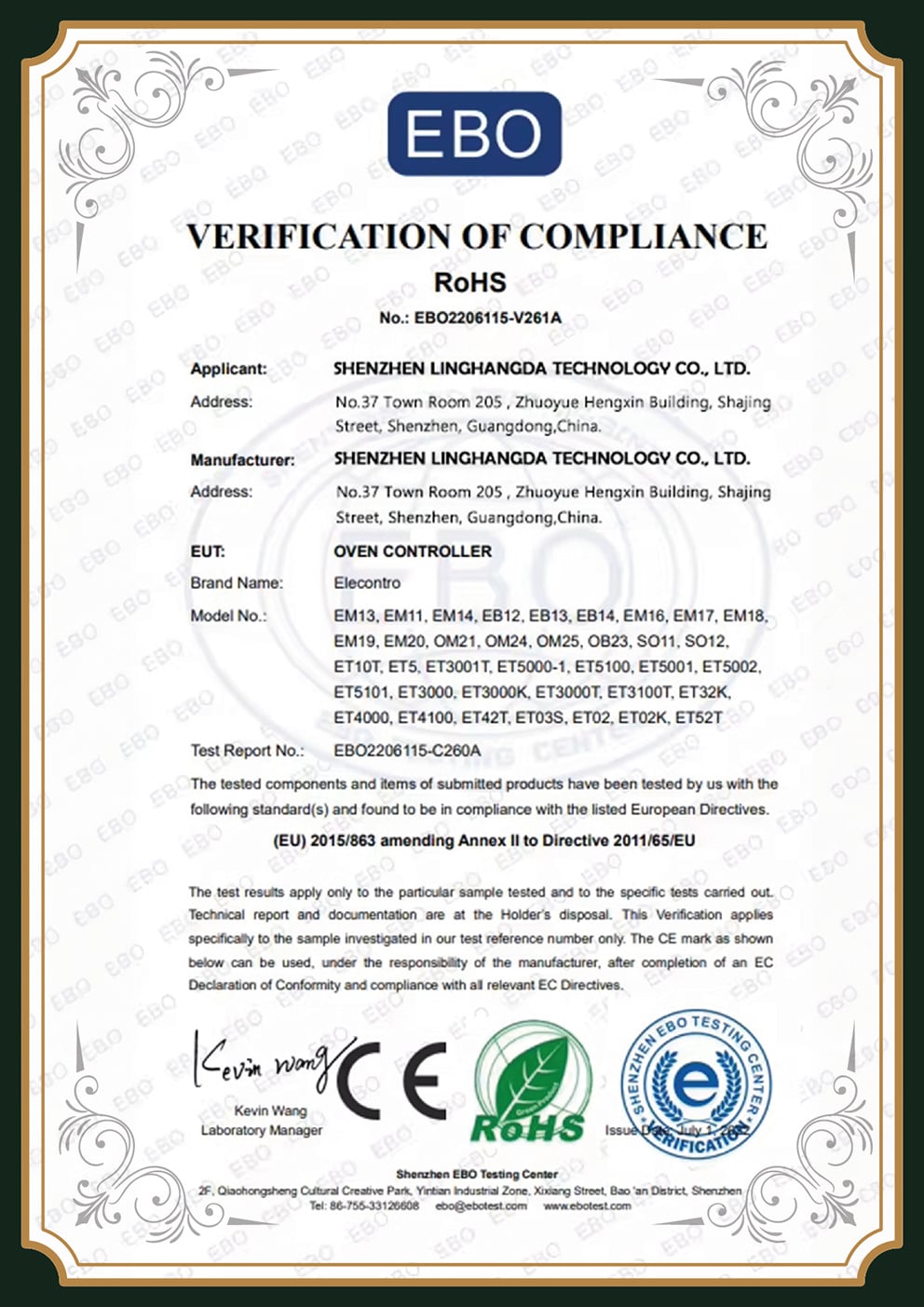
RoHS / REACH
Compliant
Frequently Asked Questions About Prototype PCB Assembly
What’s the difference between prototype and production PCB assembly?
Prototype assembly is quick-turn, small-lot (typically 1–25 boards) for design validation and uses flexible, often semi-automated setups. Production emphasizes repeatability, panelized efficiency, and cost control at scale. At PCBark both run on the same certified lines, so the transition adds no requalification.
What’s a typical lead time for prototype PCB assembly?
For 1–10 boards with in-stock parts and complete files, 24 hours expedited or 48–72 hours standard. Larger or component-sourced builds run 3–10 days. The full schedule by quantity is in the Scale Matrix above; a 24-hour turn is a premium service, not the default.
Full turnkey, partial turnkey, or consignment, which should I choose?
Full turnkey if you want one supplier to source, build, and test (most prototypes). Partial turnkey if you hold rare or long-lead parts and want PCBark to source the rest. Consignment if you already have a full kit and need assembly labor only.
Why do some cheap PCBA quotes get more expensive as I order more, or on bigger boards?
This is a real pattern engineers report: some low-cost vendors price small orders as loss-leaders, so unit price can rise with quantity. One engineer summed up the second trap, a vendor was “too expensive when you hit extended parts,” charging each time a part was swapped, “so for my low volume stuff (5 or 10 PCBs) it’s not really worth it.” Transparent landed-cost quoting avoids the surprise.
What files do I need to start?
Gerber (or ODB++), a complete BOM with manufacturer part numbers and alternates, and a pick-and-place / centroid (XYRS) file. Add assembly drawings, IPC class, and any impedance or laminate requirements. Complete data is the difference between a same-day quote and a week of back-and-forth.
Can you scale my prototype to volume production on the same lines?
Yes, that’s the core of how we work. The stackup, process parameters, panelization, and test criteria locked during the prototype build carry straight into production on the same 8 SMT lines and the same inspection stack, so there is no re-tooling, no second supplier qualification, and no data re-standardization when you ramp. This is what removes the domestic-proto-to-offshore-production handoff an NCAB field engineer describes as the hardest part of the whole process — and it is what lets your unit cost fall along the normal volume curve without a single requalification cycle eating your schedule.
Is offshore prototype assembly reliable for regulated or industrial boards?
It depends entirely on the partner. PCBark builds to IPC-A-610 Class 3, sources components through authorized distributors with full traceability, and provides Certificates of Conformance, the controls that distinguish a certified manufacturer from a low-touch broker for medical, automotive, and aerospace work.
What is the 3W rule in PCB design?
The 3W rule recommends spacing adjacent traces at least three times the trace width to limit inductive crosstalk. It’s a conservative rule of thumb, our DFM review checks it alongside IPC-2221 clearances and your real impedance targets rather than applying it blindly.
![High Frequency PCB Guide: RF & Microwave Design [2026]](https://pcbark.com/wp-content/uploads/2026/07/rf-microwave-pcb-guide-featured-1-150x150.png)