Get in touch with PCBark Company

Conformal Coating for PCBs: Types, Process & When You Need It

Conformal coating PCB decisions should begin with exposure, service access, and process control, not with a favorite resin. Conformal coating PCB refers to the decision and process for applying a protective polymer film to selected areas of an assembled circuit board. Choosing well can reduce moisture- and contamination-related risk, but no resin corrects poor cleaning, an unsuitable enclosure, unprotected connectors, or an undefined inspection plan.
This guide gives design, manufacturing, quality, and procurement teams a practical route from “Do we need coating?” to a supplier-ready specification. It also marks the claims that must be verified against the selected material data sheet and a representative coated assembly.
What conformal coating does, and what it does not do
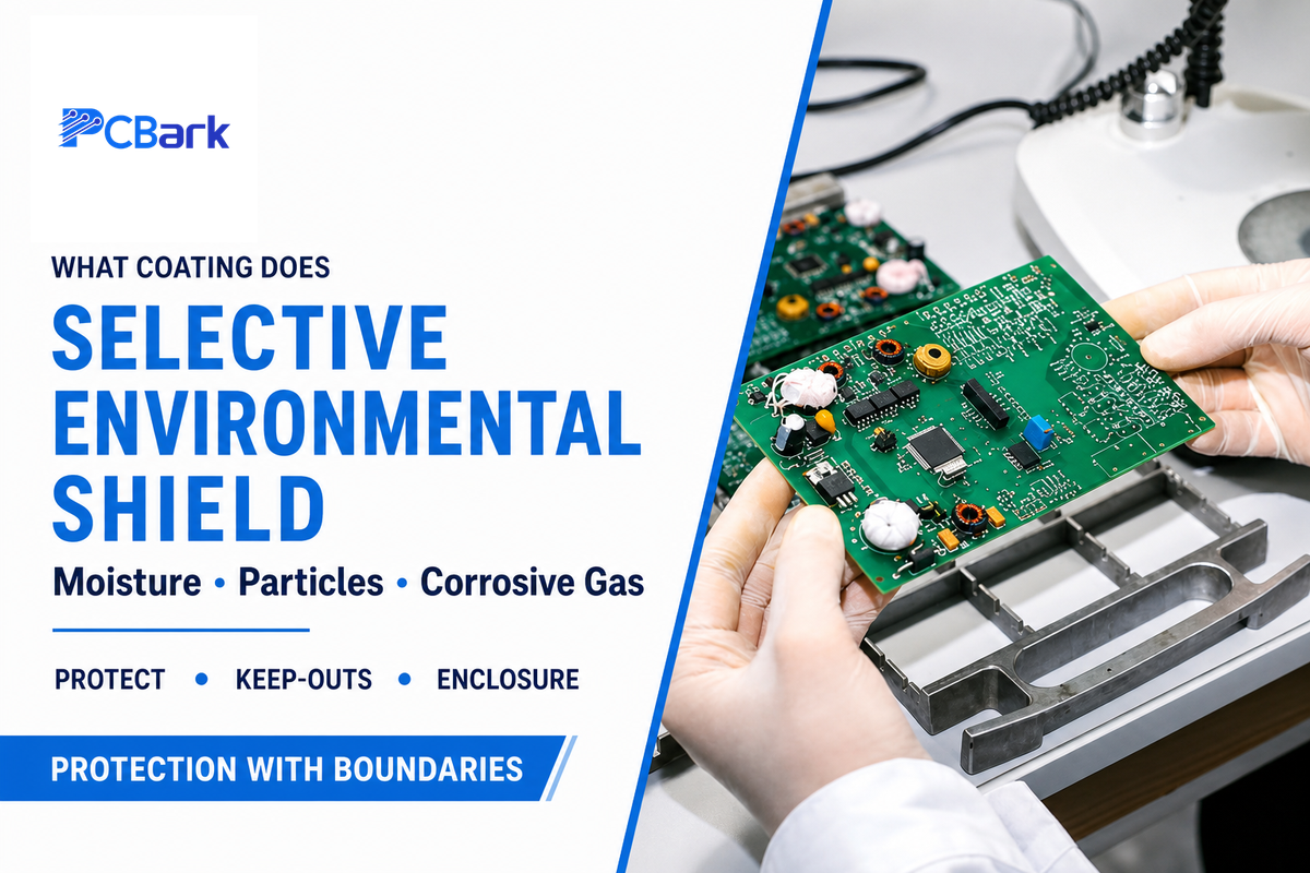
A conformal coating is a thin polymer layer applied over selected areas of a populated printed circuit board to add environmental insulation. It follows the assembly surface rather than filling the whole enclosure. Its job is to protect circuit boards from selected electrical and corrosive effects of moisture, particles, and aggressive gases, not to make every assembly waterproof or mechanically indestructible.
In its environmental-protection project, iNEMI identifies moisture, particulate matter, and corrosive gases as relevant threats. It also compares different test environments. That distinction matters because a coating is only as credible as the exposure model used to qualify it.
A circuit board conformal coating does not replace drainage, venting, connector sealing, creepage and clearance design, corrosion-resistant finishes, or a suitable enclosure. It also cannot bond reliably to flux residue, process oil, dust, or trapped moisture.
What is conformal coating on a PCB?
Conformal coating on a PCB is a selectively applied dielectric polymer film that follows components, solder joints, and board surfaces. Drawing-defined connectors, test points, switches, and thermal interfaces remain uncoated. Material, cure, thickness, and acceptance requirements depend on the formulation and exposure.
Common mistake
An instruction to “coat the whole board” doesn’t make an engineering specification useful. A usable drawing identifies coated zones, keep-outs, permissible edge creep, measurement locations, and the evidence needed to accept the finished assembly.
The Four-Exposure Coating Screen: when a PCB needs coating
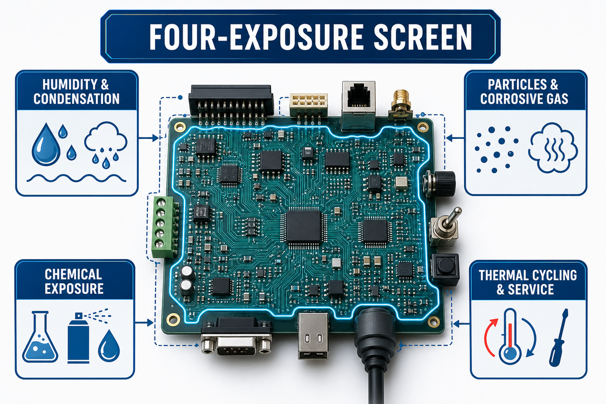
Use the Four-Exposure Coating Screen to turn a vague reliability concern into a reviewable decision. For each exposure, document the credible failure mechanism, decide whether coating changes that risk, and identify the enclosure, layout, material, or service control that still has to work. That iNEMI project record reinforces why the chosen test environment must match the threat; one “harsh environment” label is not enough.
This screen covers environmental exposure, not the complete electrical-insulation decision. Run insulation coordination separately when pollution protection is intended to justify reduced clearance or creepage. IEC 60664-3:2016 addresses assemblies protected by coating, potting, or moulding and distinguishes Type 1 microenvironment improvement from Type 2 protection treated similarly to solid insulation. Apply that route only through the program’s controlled standard and qualification evidence.
| Exposure signal | Failure concern | Coating relevance | Other control to verify | Evidence to request |
|---|---|---|---|---|
| Humidity, condensation, or wet-dry cycling | Leakage paths and corrosion | Often relevant, especially across biased conductors | Enclosure sealing, drainage, venting, spacing | Representative-board environmental test |
| Particles, salt, sulfur-bearing or corrosive gases | Deposits, dendritic growth, finish attack | Relevant when the film covers the actual vulnerable paths | Filtration, finish choice, housing and airflow | Exposure-specific qualification rationale |
| Chemical vapor, splash, cleaners, fuels, or oils | Swelling, softening, cracking, loss of adhesion | Only after formulation compatibility is shown | Material compatibility and splash barriers | Chosen-product compatibility test |
| Thermal cycling, vibration, and planned field service | Film cracking, stressed joints, costly access | Depends on flexibility, geometry, and repair strategy | Mechanical support, expansion mismatch, service access | Cycle test plus documented rework trial |
Illustrative scenario: an outdoor sensor is installed in a nominally sealed box, but daily temperature swings draw humid air through a cable entry. Reviewers should not jump straight to silicone conformal coating. First confirm the cable seal, drainage path, connector interface, powered-condensation risk, and service method; then test a shortlisted coating on the actual assembly.
Is conformal coating always necessary?
Conformal coating is not always necessary. A board inside a clean, controlled enclosure may gain little from another material and process step. It can be a poor trade when components change often, connectors cannot be masked reliably, or an enclosure redesign removes the exposure more effectively.
Conformal coating types: acrylic, silicone, polyurethane, epoxy, and parylene
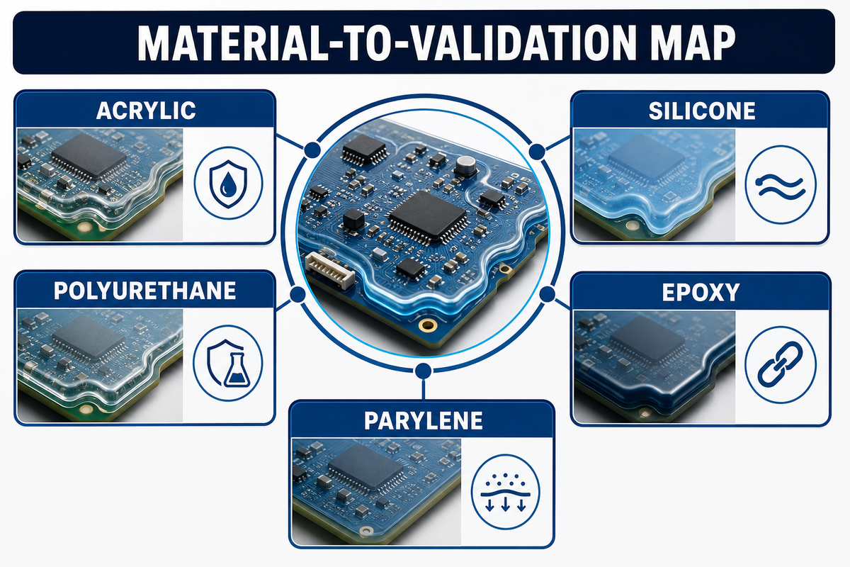
Five common conformal coating families address the various combinations of exposure, process, and service needs. These PCB coating types are starting categories, not interchangeable specifications. Acrylic is often forgiving with application and rework; some flexible conformal coatings, including suitable silicone coatings, can serve temperature cycling; polyurethane may suit chemical and abrasion exposure; epoxy is tough yet more difficult to rework; parylene uses vapor deposition to reach complex geometry.
Those are guidelines, not a performance specification. A cured coating formulation can vary in additives, cure mechanism, viscosity, adhesion, maximum thickness, and substrate compatibility within the same family. Boundaries documented in a peer-reviewed acrylic-removal study illustrate why results for one formulation and task should not be generalized across all coating families. Your selected conformal coating material data sheet and representative-board test must override a generic comparison.
| Family | Useful shortlist question | Process route to clarify | Rework concern | Validation evidence |
|---|---|---|---|---|
| Acrylic | Is serviceability a primary requirement? | Solvent handling, evaporation and full-cure evidence | Often more approachable, but remover compatibility still needs proof | Data sheet, adhesion check, exposure test, rework trial |
| Silicone | Will flexibility and thermal movement dominate? | Silicone resin cure chemistry, humidity dependence, contamination controls | Removal can be difficult and residues can affect repair | Cycle test, compatibility test, repair demonstration |
| Polyurethane (urethane) | Which chemicals and abrasion modes are credible? | Mixing or moisture control, cure profile, operator exposure controls | A tougher film can extend removal time | Chemical compatibility, cure record, rework method |
| Epoxy | Does barrier toughness outweigh field repair access? | Mix ratio, pot life, cure and stress around components | Removal may damage components or laminate | Coupon and assembly trial, repair-risk review |
| Parylene | Does complex geometry justify a specialized vapor process? | Vacuum deposition, masking, adhesion promotion | Localized removal and remasking need a defined route | Deposition record, coverage verification, repair trial |
What is the best conformal coating for a PCB?
No coating is best for every application. The best type of conformal coating is the formulation that survives the exposure, geometry, curing, inspection, and rework with acceptable manufacturing variation. Each type of coating includes products with different additives, cure conditions, and compatibility limits. Compare current supplier data sheets, record why each candidate survives the screen, and validate the short list on production-intent boards rather than a family name or a blanket application tag under the specified inspection and service plan.
How to choose the right material for the operating environment
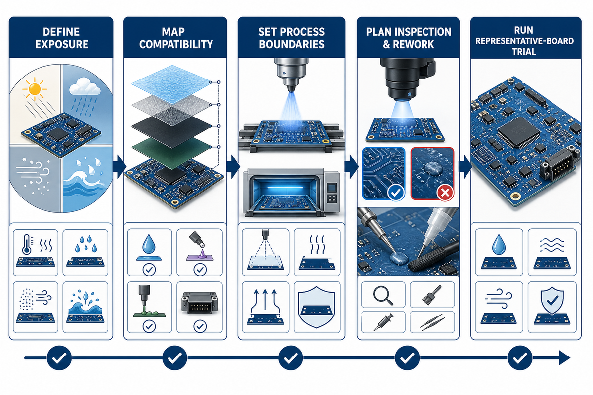
Choosing the right conformal coating works best as a sequence of eliminations. Start with the credible exposure and a test environment that represents it; the iNEMI coating-evaluation record shows why that test choice matters. Reject formulations that conflict with components or cure limits, confirm that the application process can reach the required geometry, and retain only candidates that qualify as the right coating for the program and have a workable inspection and repair plan. Final approval belongs to representative assemblies.
- First define exposure. State the humid air temperature cycle, contaminant, cleaning chemistry, corrosive gas, temperature change, or mechanical stress. “Outdoors” and “Oil and gas field” aren’t conditions.
- Next, map compatibility. Check solder mask, component packages, labels, connectors, elastomers, adhesives, and any material that may inhibit cure or lose adhesion.
- Then set process boundaries. Identify permissible cure conditions, line takt time, masking effort, selective-coating access, and areas prone to shadowing or pooling.
- Don’t approve without considering inspection and rework plans. How will coverage, keep-outs, cure, and rejects be documented? What will be done if a component needs removal and the coating must be reapplied?
- Finally, run the representative-board trial. Use production-intent boards, parts, application equipment, masks, cleaning chemistry, cure conditions, inspection plan, and rework plan.
Illustrative scenario: a serviceable industrial controller has solvent exposure near one edge but replaceable relays and test points across the board. A chemically resistant film may look attractive until removal risk, mask repeatability, and repair time are included. In that case, the preferred route could be selective coverage plus a stronger enclosure barrier rather than maximum coating everywhere.
A material family narrows the search. The actual specification is the chosen formulation, the controlled application route, and the acceptance evidence on the representative assembly.
PCB conformal coating process: clean, mask, apply, cure, and inspect
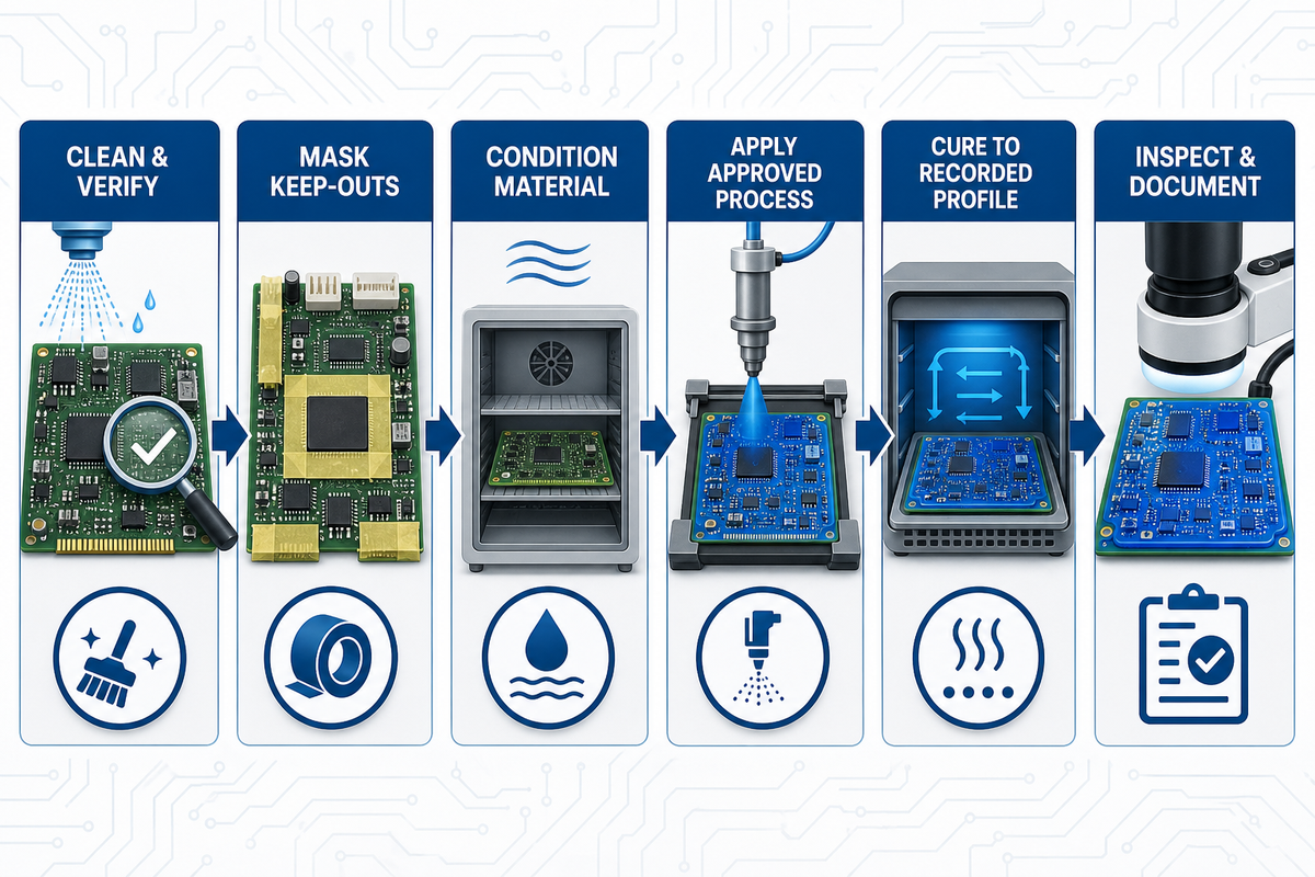
Controlled PCB conformal coating links each operation to an acceptance record. Cleaning prepares the board, masking protects defined functional keep-outs, deposition applies the coating material, cure builds the desired film, and inspection determines success. Here, the official IPC revision table distinguishes application guidance from qualification and performance; the actual process values still belong in the controlled program documents. Missing evidence at any stage leaves later failures difficult to diagnose.
- Start by cleaning and verifying. Remove flux residues, oils, dust, and moisture using a process compatible with the assembly. A “no-clean” label is not proof that residue is compatible with the chosen coating: a 2024 study of three coatings found that residue condition materially affected adhesion and protection under its test conditions. Treat that result as a compatibility warning, not a universal ranking. Define what constitutes a clean, dry board and retain the relevant process record.
- After cleaning, mask defined keep-outs. Protect connector contacts, test points, switches, adjustment features, grounding areas, thermal interfaces, and other drawing-controlled exclusions. Inspect the mask before coating.
- Before application, condition the material. Follow the selected supplier’s rules for mixing, dilution, viscosity, temperature, filtration, pot life, and handling. Do not transfer generic values from another resin or product.
- For deposition, begin by applying the coating with the approved process. Brush can suit localized liquid coating repair; manual spray coating offers flexibility; dip coating can support repeatable volume with demanding masking; selective coating targets programmed zones.
- Under controlled conditions, cure to a recorded profile. Cure may depend on time, temperature, humidity, ultraviolet exposure, or more than one mechanism.
- At release, inspect, demask, and document. Check coverage, keep-outs, bubbles, voids, runs, pooling, contamination, damage, and specified thickness locations.
Engineering note
Both cure time and specified coating thickness are product- and process-specific. List the manufacturer data-sheet revision and revision date; when measuring coating thickness, describe the test method, including where and how measurements are made; record cure and acceptance results on the traveler. Generic “web data” is not an acceptable substitute for tested product data.
How do you apply conformal coating on a PCB?
Prepare a clean and dry assembly, mask drawing-defined keep-outs, condition the chosen material, and apply it by an approved brush, spray, dip, dispensing, or selective-coating process. Cure under the product’s documented conditions. Inspect coverage, exclusions, defects, and specified measurement points; link material lot, recipe, cure, and inspection records to the finished assembly. Confirm pot life, viscosity, and equipment settings against the current product data and approved production traveler. Trial the programmed path on representative boards before releasing volume production.
Translate search language into controlled requirements
Treat a guide to conformal coating, or a page promising everything you need to know about conformal coating, as orientation only. It cannot replace PCB design inputs, verified properties of the coating, or a controlled coating application.
When selecting a coating, start with exposure, compatibility, cure, inspection, and service access. The benefits of conformal coating depend on that complete match, not on a family label.
Before applying the conformal coating, qualify the selected equipment and recipe on the assembly. A conformal coating can be applied by several routes, including a controlled spray gun process, but the equipment name alone does not define coverage or acceptance.
Statements such as “conformal coating is a protective film” and “conformal coating is applied after assembly” are incomplete specifications. Do not define conformal coating by using only a generic process label.
Replace an approximate dry coating thickness with controlled limits and named locations before and after coating. Include leads, edges, shadow zones, and any exposed metal under the coating; material chemistry and cure conditions form the polymer coating that the inspection plan must evaluate.
Thickness, coverage, keep-outs, and inspection
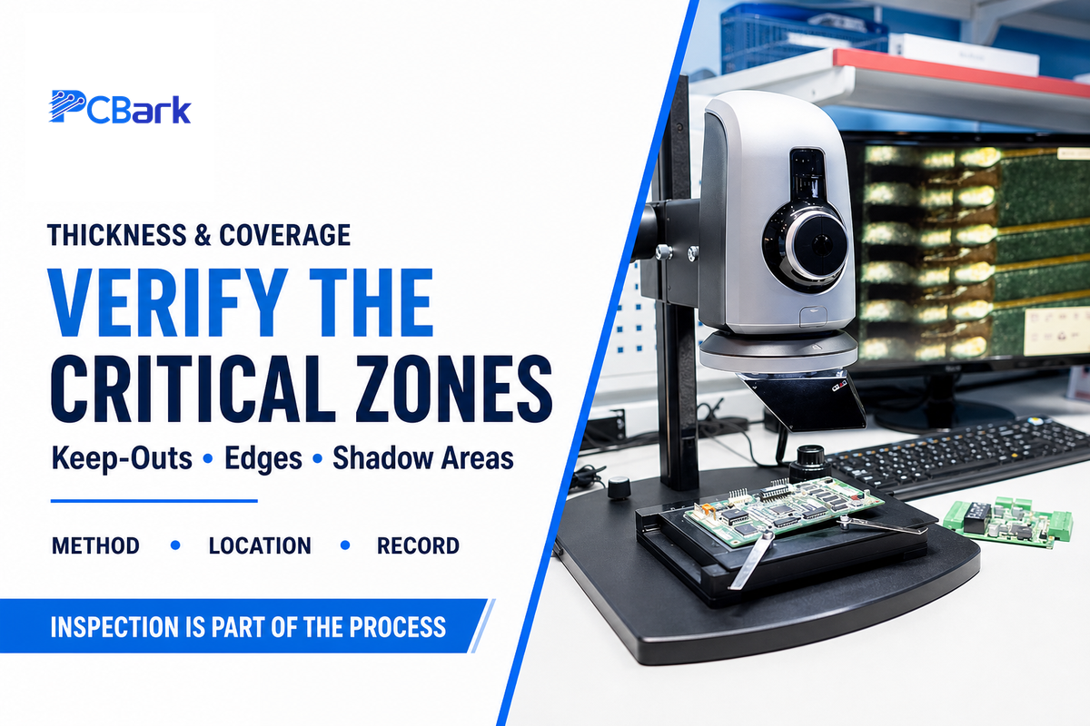
A conformal coating inspection must answer two independent questions: Is coating present where it’s needed for protection, AND is coating absent where it isn’t needed and may inhibit function? You can’t answer either question by testing coating thickness at a single or averaged spot. Your design and your inspection plan should identify specific zones, boundaries, thickness reference points, defect criteria and method(s) of measurement.
- Record the coating manufacturer and lot/batch number, process path, cure method, date, and results.
- Inspect critical features on components as well as flat, open PCB laminate. Look at leads, edges, and shadows where coating would be missed and where it might pool.
- Confirm conformance at such points as connector pin faces and bodies, exposed contacts, test points, switch actuators, heatsink contact surfaces and defined grounding points.
- Use the specified wet- and dry-film measurement method at named test points; visual inspection is an adjunct, but insufficient on its own.
- Document defects, disposition, repair material, local cure, and reinspection.
Ultraviolet fluorescence can assist coverage inspection when the formulation includes a suitable tracer. WO2009120951A2 discloses one camera-based automated approach. It is a Nordson-assigned patent example—not an independent standard, a universal requirement, or PCBark-owned technology. The official IPC revision table identifies the governing coating documents, but inspection locations and acceptance limits must come from the controlled specification used by the program.
How do you measure conformal coating thickness and coverage?
Use an approved method with named measurement locations and limits from the governing specification or product documentation. Visual inspection can find runs, voids, bubbles, pooling, and keep-out breaches; ultraviolet fluorescence can support coverage checks when the formulation contains a suitable tracer. Thickness evidence may come from wet-film measurements, cured coupons, dry-film methods, or cross-sections, depending on the product and assembly. Record which method answers which acceptance question.
Standards, qualification, and documentation questions to ask
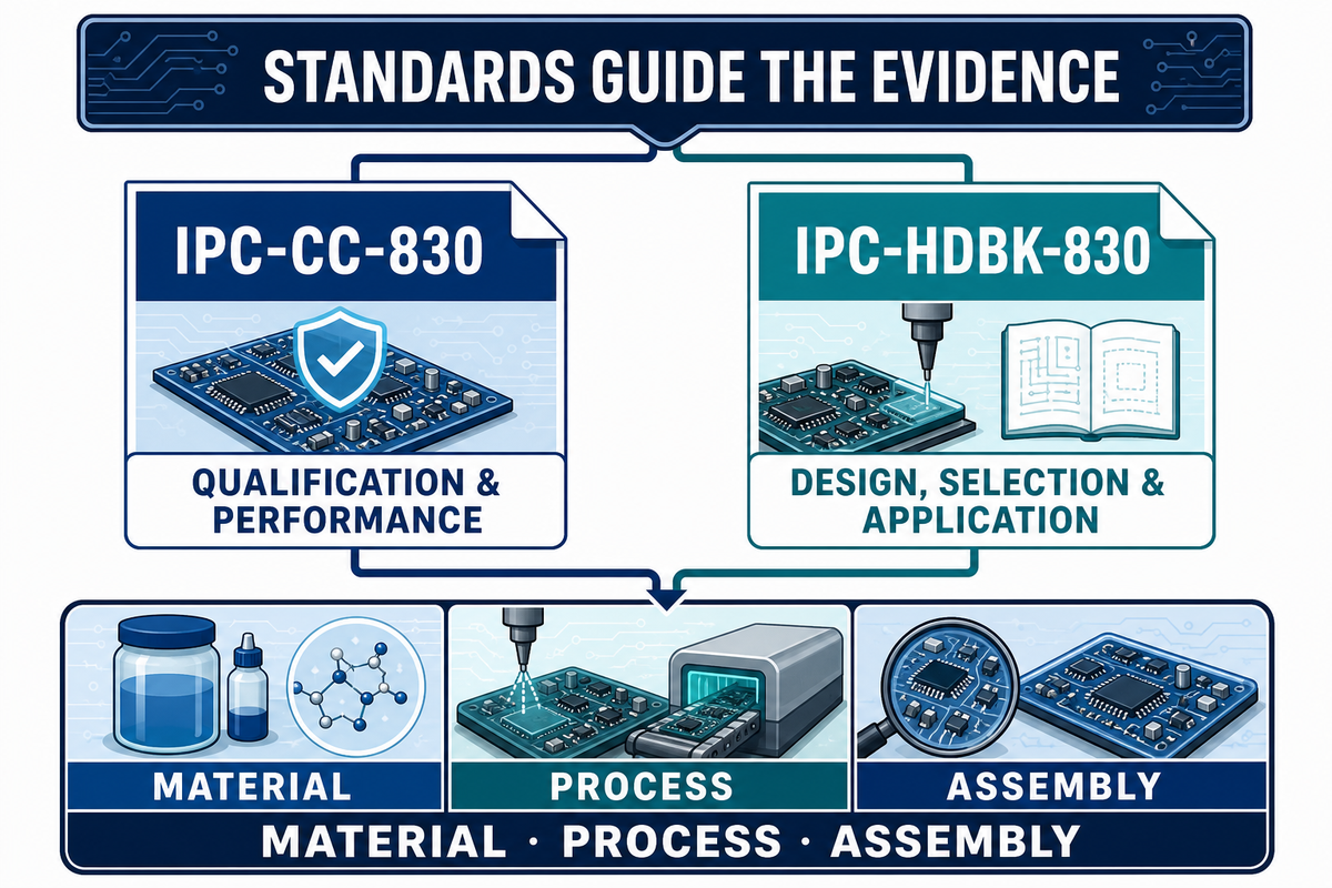
Standards should define the evidence conversation, not serve as a vague badge. IPC’s public revision record distinguishes a qualification-and-performance document from an application-guidance handbook. Neither public title alone proves that a supplier, material, process, or finished assembly satisfies your program’s acceptance requirements.
| Document | Publicly verified scope | What the buyer must still request |
|---|---|---|
| IPC-CC-830, Revision C | Qualification and Performance of Electrical Insulating Compound for Printed Wiring Assemblies | Material identity, qualification evidence, applicable test scope, current documents, and assembly acceptance plan |
| IPC-HDBK-830, Revision A | Guidelines for Design, Selection and Application of Conformal Coatings | Which guidance is applied to layout, keep-outs, process selection, inspection, and rework |
Exact titles and revision rows are visible in the official IPC document revision table. That public page doesn’t supply a universal coating thickness, cure profile, or finished-board acceptance value, so those details must come from the controlled documents that actually govern the program.
Ask whether the evidence applies to the coating material, the application process, or the completed assembly. Those are different claims. Also request the data-sheet revision, batch traceability, process traveler, change-notification rules, defect disposition route, and records retained for the finished boards.
Conformal coating vs potting: choose the protection strategy, not a product name
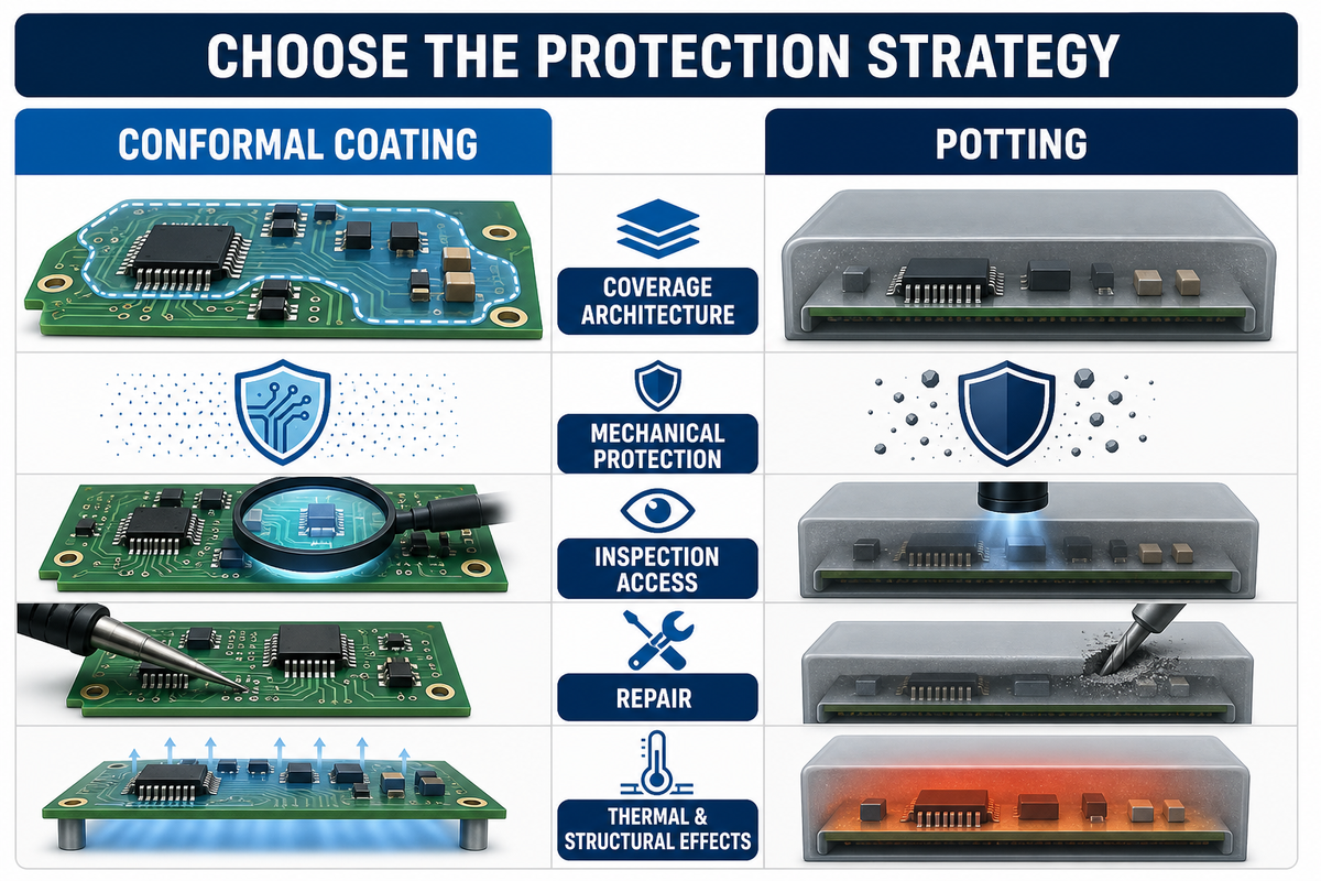
Conformal coating preserves access and follows the assembly surface; potting surrounds more of the assembly in a larger mass of material. Coating usually fits contamination and electrical-insulation risks where inspection and repair still matter. The iNEMI project record supports the environmental-protection side of that decision but does not compare coating with potting. Potting is considered when stronger encapsulation and mechanical protection outweigh added mass, heat-flow changes, and difficult rework.
| Decision factor | Conformal coating | Potting or encapsulation |
|---|---|---|
| Coverage architecture | Thin, selective surface film | Assembly surrounded by a larger material volume |
| Mechanical protection | Limited; depends on film and geometry | Can be substantially stronger, subject to formulation and design |
| Inspection access | Often retained with planned keep-outs | Restricted after encapsulation |
| Repair | Possible when a validated removal and recoating route exists | Often difficult or destructive |
| Thermal and structural effects | Usually smaller, still needs compatibility review | Material mass, expansion, stress, and heat flow require system analysis |
Disadvantages, rework, and failure modes to plan for
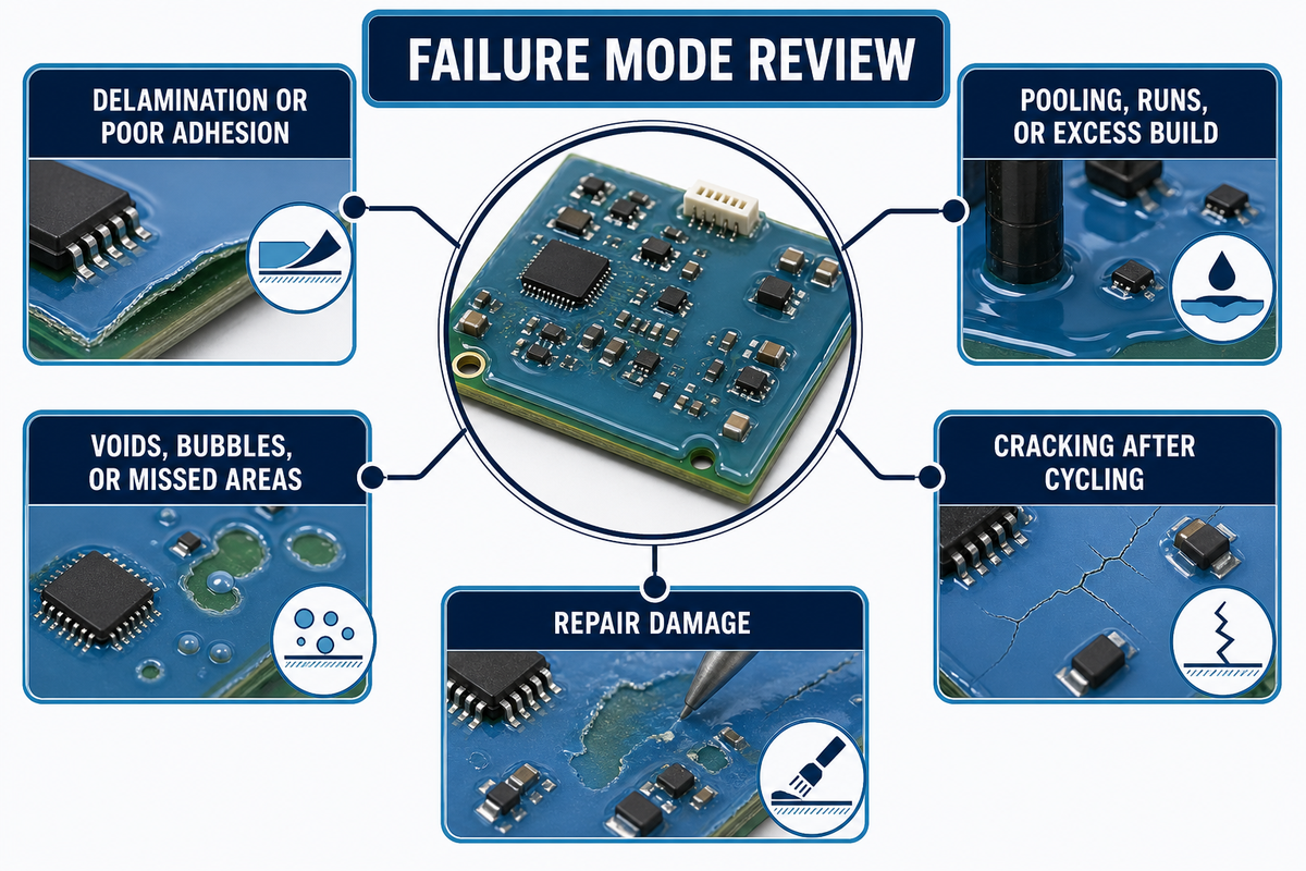
Every coated assembly adds material, masking, cure, inspection, and documentation steps. Coating can obstruct probes, conceal contamination, complicate solder rework, or trap a poor process beneath a convincing surface. These trade-offs are manageable only when removal, local repair, recoating, and reinspection are qualified before production.
Researchers in a peer-reviewed study on safer solvent approaches examine removal of acrylic conformal coating. Their results show why solvent choice and exposure controls matter, but don’t create a universal removal recipe. Polyurethane- and silicone-based systems are explicitly distinguished as more difficult to remove.
Removal language needs a safety boundary
To remove a conformal coating, use a coating-specific work instruction, verified compatibility, local exposure controls, and a defined reinspection boundary. Claims that conformal coatings can be peeled describe only certain materials and conditions; no single common technique of coating removal applies to every resin or assembly.
Search fragments such as “coating removal is to simply…” or “simply burn through the coating” are not safe production instructions. Heating coating with a soldering iron can expose the board, components, operator, and joint to uncontrolled thermal or decomposition risk, so any thermal route requires a validated procedure and appropriate controls.
Some references state that micro blasting removes the conformal coating from a local area. That phrase also appears as “blasting removes the conformal coating,” but neither wording defines media, pressure, masking, substrate limits, residue control, or acceptance; qualify all of those before production use.
| Failure mode | Likely process question | Required response |
|---|---|---|
| Delamination or poor adhesion | Was the surface clean, dry, and compatible? | Contain the lot, verify preparation, repeat adhesion evidence |
| Voids, bubbles, or missed shadow areas | Did viscosity, application angle, or component geometry prevent coverage? | Correct process parameters and reinspect critical zones |
| Pooling, runs, or excessive local build | Was too much material applied or drainage restricted? | Review geometry, recipe, cure and local acceptance rule |
| Cracking after cycling | Is the film compatible with thermal and mechanical movement? | Revisit material, thickness, geometry, and cycle qualification |
| Repair damage | Was removal chemistry and heat exposure validated? | Use a coating-specific work instruction and recoat boundary |
What are the disadvantages of conformal coating?
Conformal coating adds material cost, cycle time, inspection, and process controls. Conformal coating defects such as pooling, voids, or keep-out breaches can compromise performance. The film can obstruct probe access and rework, and unsuitable removal can damage the complete assembly.
Harsh-environment and aerospace PCB considerations
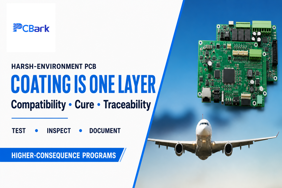
Harsh-environment programs should treat coating as one layer in a wider PCB durability plan. Materials, stack-up, finishes, component termination, cleanliness, enclosure design, assembly process, inspection, test, traceability, and service strategy still determine whether the complete circuit board can meet the requirements for its intended exposure.
For higher-consequence programs, the review should connect the coating requirement to program-specific acceptance evidence. Any chosen accelerated test must represent the intended threat; the iNEMI work comparing corrosive-gas test environments illustrates why the test environment itself is an engineering choice rather than a generic box to check.
Space and contamination-sensitive programs add a different evidence question: outgassing under vacuum. NASA’s outgassing database guide includes conformal coatings and records metrics such as total mass loss, collected volatile condensable materials, and water vapor regain together with material-specific cure conditions. Use database results as selection evidence, then verify the exact formulation, cure state, and lot or program requirement; formulation and processing changes can limit transferability.
Consider an avionics-adjacent control assembly undergoing low-pressure cycles, extreme temperature variation, service restrictions, and traceability requirements. Coating might be warranted, but the program still needs compatibility review, keep-out specification, representative boards, controlled cure, inspection reports, and a disposition route for repairs.
See PCBark’s aerospace PCB manufacturing considerations for broader first-party context on fabrication and assembly. That page is not used here as independent evidence of coating qualification or performance.
The Process-Control RFQ Matrix for coated PCB assemblies
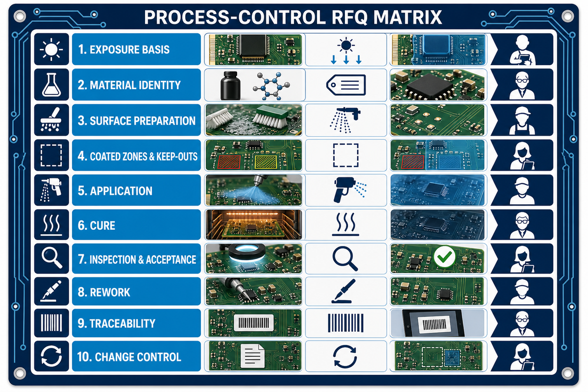
The Process-Control RFQ Matrix separates material qualification from assembly-specific manufacturing evidence. The official IPC revision table confirms that qualification/performance and design/application guidance are distinct document scopes; the matrix turns that distinction into buyer questions without inventing acceptance values. Procurement can use it to compare responses without forcing every supplier into the same equipment route. Quality and manufacturing teams can then turn the accepted response into drawings, travelers, inspection records, and change-control obligations.
| RFQ control category | Buyer supplies | Supplier returns | Owner |
|---|---|---|---|
| 1. Exposure basis | Condensation, contaminant, chemical, cycle, and service profile | Material-selection rationale and limitations | Design / reliability |
| 2. Material identity | Required family or performance envelope | Product, revision, data sheet, qualification evidence, shelf-life controls | Materials / procurement |
| 3. Surface preparation | Assembly materials and cleanliness requirement | Cleaning route, drying verification, process record | Manufacturing / quality |
| 4. Coated zones and keep-outs | Drawing, coordinates, boundary tolerance, critical locations | Masking method and pre-coat verification | Design / manufacturing |
| 5. Application | Coverage and appearance requirements | Brush, spray, dip, dispense, or selective route; recipe controls | Manufacturing engineering |
| 6. Cure | Assembly temperature and process constraints | Cure mechanism, actual profile, verification and handling window | Manufacturing / quality |
| 7. Inspection and acceptance | Defect classes, measurement locations, sampling or full inspection | Visual or UV method, thickness method, records and defect images | Quality |
| 8. Rework | Permitted repair scope and component-access needs | Removal, cleaning, recoating, local cure and reinspection route | Service / quality |
| 9. Traceability | Record-retention and serialization requirements | Material lot, operator or equipment, recipe, cure and inspection linkage | Quality / program |
| 10. Change control | Notification and requalification triggers | Material, formulation, equipment, recipe, site, and inspection-change rules | Procurement / quality |
A complete response makes assumptions visible. If the supplier proposes a different coating family or process, ask what risk it changes, which evidence supports the change, and whether a new representative-board trial is required.
Frequently asked questions
Is conformal coating worth it?
Conformal coating may be worth it when credible environmental exposure poses a risk to electrical function or corrosion and the product enclosure alone can’t sufficiently mitigate that risk. That comparison should weigh the anticipated risk reduction against the added cost and complexity in terms of cleaning procedures, masking operations, cure process control, inspection, rework, and documentation. A representative-board test offers more compelling evidence than a generic assertion of material properties.
Are conformal coatings waterproof?
Don’t specify conformal coating as a catch-all “waterproofing” solution. Such a film can reduce the effects of humidity, condensation, or some contaminants; however, connectors, component edges, internal voids, physical damage, immersion, pressure, and enclosure leakage may remain more important. Define the intended water exposure and test the complete assembly under representative conditions.
How long does conformal coating take to dry or cure?
There is no universal cure time. It depends on the exact product, film build, temperature, humidity, airflow, ultraviolet dose where applicable, and the difference between touch-dry and full cure. Use the current supplier data sheet, validate the production profile, and record the acceptance evidence before handling or test.
Can conformal coating affect PCB repair or rework?
Conformally coated boards can complicate testing and repair through concealed test points, blocked probe access, longer test time, solvent or heat exposure, and local cleaning and reapplication after component replacement. Rework difficulty varies widely with the formulation. Before proceeding, validate the removal tool, cleaning-chemical compatibility, heat limits, the exposed coating boundary, local cure requirements, and the final inspection method on representative boards.
Include a hands-on “practice” repair in the validation plan: remove and replace a component with the planned solder process, perform local cleaning, restore the coating boundary, complete the local cure, and run the final inspection. This exercise shows whether the written procedure works without turning a production board into an experimental one.
Turn the coating requirement into a manufacturable assembly plan
PCBark supports PCB fabrication, assembly, design-for-manufacturing review, component sourcing, and functional testing. Provide your exposure profile, board files, keep-outs, all relevant conformal coating documentation, inspection criteria, and rework procedures so that the manufacturing discussion begins with controlled inputs.
References & Sources
- IPC Document Revision Table official titles and revision context for IPC-CC-830 and IPC-HDBK-830.
- iNEMI Conformal Coating Evaluation for Improved Environmental Protection, Phase 2 exposure and test-environment framing.
- Removing Acrylic Conformal Coating with Safer Solvents for Re-Manufacturing Electronics peer-reviewed, acrylic-specific removal study.
- IEC 60664-3:2016 public scope for pollution protection through coating, potting, or moulding and Type 1/Type 2 protection.
- Compatibility Study of No-Clean Flux Residue and Conformal Coatings 2024 peer-reviewed, three-coating test with explicit scope limits.
- NASA Outgassing Database User Guide spacecraft-material selection, outgassing metrics, and cure-condition context.
- WO2009120951A2: Automated Conformal Coating Inspection System and Methods of Use Nordson-assigned patent example, not an independent standard.
WHY WE WRITE THIS
About PCBark Engineering Insights
PCBark shares technical PCB fabrication and assembly guides based on real engineering review and manufacturing experience. We help teams compare materials, stackups, DFM risks, component sourcing, inspection plans, and production routes before they move from prototype to volume builds.
16+ yrs EMS experience
1-42 PCB layers
500,000 m2 annual PCB capacity
IPC Class 2/3 build discipline
DFM + test review






![High Frequency PCB Guide: RF & Microwave Design [2026]](https://pcbark.com/wp-content/uploads/2026/07/rf-microwave-pcb-guide-featured-1-150x150.png)