Get in touch with PCBark Company


Updated July 2026
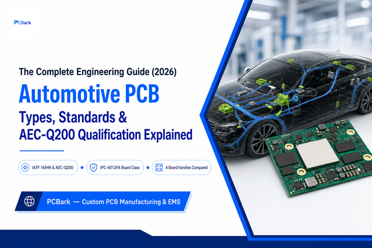
An automotive pcb is a printed circuit board built and qualified to survive a vehicles operating environment— routinely -40C to 125C or higher, constant vibration, and years of thermal cycling— and to provide the documentation trail (AEC-Q200, IPC-6012FA, IATF 16949) that OEMs and Tier-1 buyers require before they’ll qualify a supplier. This guide covers what actually changes from a consumer-grade board to one built to automotive standards, the four board families used across the vehicle, the standards a buyer should fact-check (not blindly trust), and how suppliers are changing sourcing decisions as qualification-proof requirements accelerate through 2026. Every automotive printed circuit board in a modern vehicle, from a body-control module to a battery-management board, goes down this exact same qualification path regardless of how simple its pcb design look on paper, and understanding the manufacturing process behind that qualification is what separates an authentic automotive-grade supplier from one that just took the label.
Quick Specs
| Operating temperature range | -40°C to 125°C+ (Grade 1, AEC-Q200) |
| Board-level standard | IPC-6012FA (Dec 2025), replaces IPC-6012DA |
| Facility qualification | IATF 16949:2016 (Rules 6th Ed. audit changes eff. Jan 2025) |
| Copper weight range | 1oz to 3oz+ external, per IPC-2152 current-carrying tables |
| Board families | Standard multilayer, rigid-flex, metal-core (MCPCB), HDI |
What Is an Automotive PCB?
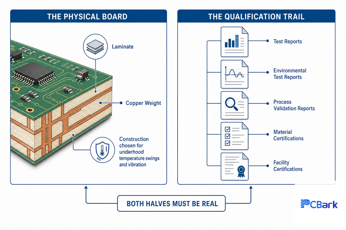
An automotive PCB is a printed circuit board custom-designed and documented to a set of automotive requirements, rather than generic consumer standards. Two things define it: the physical board — laminate, copper weight, and construction chosen to survive underhood temperature swings and vibration — and the qualification trail, the test reports and facility certifications proving it was actually built and tested to automotive standards.
Those two halves aren’t interchangeable, and the second one, the paperwork, is easy to claim without earning.
That latter half, the paperwork, appears to be more significant than most buyers assume. AEC-Q200 is a stress-qualification spec for passive components mounted on the board (resistors, capacitors, inductors), not the bare board itself. Separately, the board and its fabrication process are qualified through IPC-6012FA at the product level and IATF 16949 at the facility level. A board can be fabricated to IPC Class 2—the same class used for many consumer standards, and still legitimately be called “automotive” simply because of the qualification package assembled around it. None of the three competitor articles examined for this guide do that distinction; most describe “AEC-Q100/Q200 certified board” as if the component spec covers the board itself.
📐 Engineering Note
The AEC-Q200 basic range is -40C to +85C; component manufacturers frequently extend Grade 1 parts to 125C, and Grade 0 parts to 150C. Test methods referenced by the spec include JESD22-A104 (temperature cycling), MIL-STD-202 Method 204 (vibration), and Method 213 (mechanical shock) — request the actual test report against these methods, not just a grade number on a datasheet.
PCBark fabricates to IATF 16949 and IPC-A-610 Class 2 & 3 out of a 500,000 sqm/yr facility footprint, the same facility-level certification this guide recommends every buyer fact-check prior to sending drawings.
One question settles most “do I really need automotive-grade?” debates: does this board’s failure create a safety, warranty, or recall risk once it’s in a vehicle? If the answer is yes, qualify it as automotive-grade from the first design review, retrofitting AEC-Q200 and IATF 16949 paperwork after a design freeze costs far more in schedule and re-testing than specifying it upfront.
How Automotive PCBs Differ From Standard PCBs
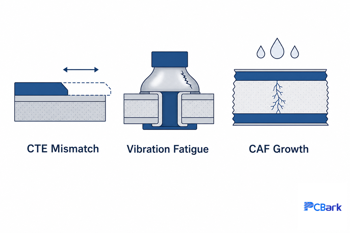
The honest answer is less about the board itself than marketing copy suggests, and more about three failure modes the industry has learned to prevent: CTE (coefficient of thermal expansion) mismatch between copper and laminate, vibration-induced fatigue of solder joints and plated vias, and conductive anodic filament (CAF) growth between copper traces under humidity and voltage over time.
These map directly onto SAE’s physics-of-failure standards for automotive electronics (J3168, J1879, J3083), which group failure causes into component-level mechanisms — electromigration, oxide breakdown, bias-temperature instability, hot-carrier injection — and one board-level mechanism: fatigue from mechanical and thermal stress, the category the three failure modes above all belong to.
| Factor | Consumer PCB | Automotive PCB |
|---|---|---|
| Operating range | 0°C to ~70°C typical | -40°C to 125°C+ (Grade-dependent) |
| Board-level standard | IPC Class 1-2, general acceptance | IPC-6012FA addendum, Class 2-3 |
| Facility qualification | ISO 9001 (typical baseline) | IATF 16949 facility audit |
| Test regime | Visual + basic electrical test | AOI, X-ray, ICT, functional test to AEC-Q/JESD methods |
| Typical qualification lead time | Days to a few weeks | Weeks to months (PPAP + facility audit trail) |
✔ Advantages of the automotive qualification path
- Documented failure-mode testing (JESD22-A104, MIL-STD-202) traces back to a real test report, not a marketing claim
- IATF facility audits catch process drift a one-time board inspection can’t
- Qualification package is portable across OEM RFQs once earned
⚠ Limitations
- Qualification lead time and cost are real, this isn’t a same-week turnaround category
- A qualified facility doesn’t automatically mean every board it ship is automotive-grade; check the specific PO’s spec sheet
Automotive PCB Board Types: The 4 Board Families
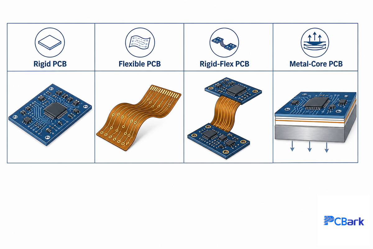
You’ll likely find the board type listed on the various automotive pcb pages in a flat catalog form. However, the far more important question to ask is which type is best suited for a specific subsystem, and why – a design question, not just a terminology lookup. Among the available automotive pcb boards, the extremes are the two fully rigid pcbs and flexible pcbs board families, or a hybrid of the two, in cases where there’s an assembly that has to be able to flex or bend. High thermal conductivity designs are typically on the metal core pcbs side of the spectrum.
| Family | Selection driver | Typical subsystem |
|---|---|---|
| Standard multilayer rigid | Moderate current, dense digital routing, cost-sensitive | Body control modules, infotainment head units |
| Rigid-flex | Dynamic or tight-bend-radius routing between assemblies | Steering column electronics, folding/moving assemblies |
| Metal-core (MCPCB) | High thermal dissipation, LED/power-device heat spreading | Headlight and brake-light LED modules |
| HDI-dense digital | High pin-count processors, fine-pitch BGA routing | ADAS domain controllers, high-performance ECUs |
The other tunable feature is copper weight within any given board family. In IPC-2152, the standard replaced an old flat rule approach with charts generated from actual experiments performed under various temperature rises, which commonly include 10 C, 20 C, and higher. A popular rule of thumb, which has been derived from this data, states that increasing copper weight by a factor of two, from 1 ounce to 2 ounces, will double a given traces current-carrying capacity at a specific temperature rise, but it’s best to check the specific chart, as the relationship will vary slightly based on traces’ width and the desired temperature rise. It should also be noted that while IPC-2152 doesn’t prescribe specific charts to particular industries-it’s left to the designer’s preference-a board designed for a low underhood thermal budget may call for a lower temperature rise curve than would be suitable for consumer-grade electronics with the same traces carrying similar currents. Adding an adjacent ground or power plane at roughly 100 microns spacing is commonly cited as adding meaningful extra headroom over a trace on its own, though the actual figure vary with the fabricator’s stack-up, so confirm it rather than treating a generic industry number as a strict rule.
💡 Pro Tip
When extreme-power levels are involved (such as those found in SiC inverter and traction-drive modules for EV applications), the choices shift even beyond these four main categories to Ceramic DBC (direct-bond-copper) or IMS (insulated metal substrate), where issues of thermal spread and CTE matching are critical considerations. See our Ceramic PCB guide for a full comparison.
Materials and Environmental Requirements
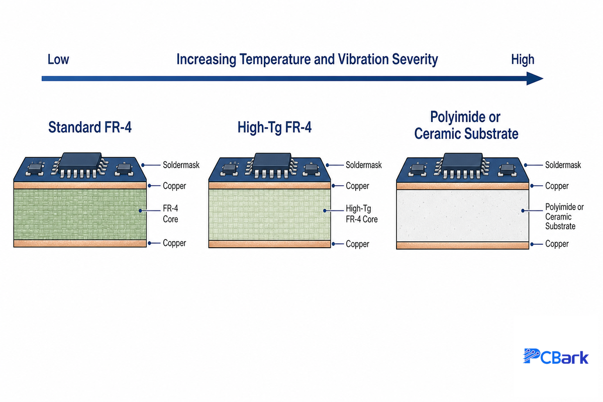
All automotive pcb materials and most assembly selection is driven by one design consideration: a shortcut on material choice or assembly visible on the consumer product become a field failure on the automobile in just a few years, because the automotive pcbs has to do so much to maintain vehicle safety. Lamination for automotive applications will survive a wider and tougher temperature envelope than a simple “high-Tg” statement implies; most automotive PCBs use a higher glass-transition-temperature (Tg) FR-4 variation, and where higher temperature or higher vibration environments are encountered (e.g., under the hood), ceramic-filled PTFE or flame-retardant fiberglass epoxies rated well in excess of 125 C (Grade 1) temperatures come into play. Typical copper weights are 1-3 oz or higher on outer layers, sized against the IPC-2152 current tables (see below), not a rule of thumb.
Key Factors to Consider — Laminate Grade by Mounting Zone
- Engine compartment / exhaust mounted (highest temperature/closest to Grade 0) requires Grade 0 or 1 based PCB substrate
- Under the dash / in the passenger compartment (moderate temperature) typically requires a Grade 2 or 3 PCB substrate (less expensive).
- If any trace carrying >~ 2A has significant current density, double check with IPC-2152 tables for necessary conductor width to stay under laminate thermal margin.
None of the other three competitor pages review sites make a recommendation about how to apply this selection criteria in the application – all make reference to “automotive grade” without any methodology for deciding WHICH automotive grade material.
Why Is Thermal Management Important for Automotive PCBs?
Thermal cycling is the main failure mechanism for a design that isn’t rated properly. Every drive cycle, the PCB expands and contracts with ambient and operating temperatures — a swing that’s widest for components under the hood or near the engine compartment — putting stress on solder joints and plated through-holes. Over thousands of cycles, that movement accumulates into fatigue failure.
This is exactly the mechanism SAE’s reliability-physics standards catalog for automotive electronics. Thermal vias alone won’t solve it — the fix is routing those internal copper planes as real heat sinks, with a path from the high-heat source to them, verified with a thermal simulation or a prototype-board thermal scan rather than assumed.
Automotive PCB Standards and Qualification
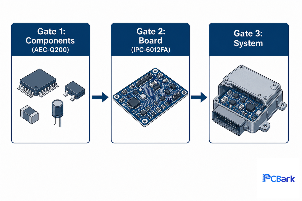
Almost every supplier of automotive pcb will mention these three certifications; what most don’t consider is whether these certifications actually mean what they’re implied to mean:
The 3-Gate Automotive PCB Qualification Path
- Gate 1 – Components (AEC-Q200): reports that the components on your board passed passive component stress testing. Be sure you request test reports conforming to JESD22-A104/MIL-STD-202, not just the “Grade 1” identifier.
- Gate 2 – Board (IPC-6012FA): the current industry performance specification for the finished board. This addendum, added in December 2025, addresses back-drilled structures, microvias, and acceptance of boards with built-in cavities; it replaces the older IPC-6012DA still referenced on most competitor pages.
- Gate 3 – Facility (IATF 16949) – quality-management-system audit of the entire fabricator’s facility rather than an individual board run.
This failure to verify these three gates beforehand leaves buyers with the painful discovery of the disparity only after the PPAP submission has been rejected midway through a program – an expensive lesson on the correct standard to learn compared to simply asking the fabricator for the paperwork when obtaining quotes.
This fresh reference is why this topic is significant.IPC-6012DA(April 2016) continues to be the spec that’s still used and Googled most frequently throughoutautomotive pcb supplier sites, and was found on each of the three competitor pages in this article.However, that standard has now been replaced by ipc-6012F(October 2023) along with the automobile supplement IPC-6012FA, both published in december 2025.If a supplier only shows ipc-6012DA on its specification, it may be appropriate to directly ask them what level of process their equipment complies to.
For the facility, IATF Rules 6th Edition became effective Jan 1, 2025, but affects how audits are administered, – including calculations for performance-based audit day – and includes a broadened definition of a manufacturing site (facilities located within a certain radius (10 miles/16km, 60-min drive) can be audited as one location – not the quality requirements of IATF 16949:2016. The fully updated standard for IATF 16949:2016 is expected around late 2026 or 2027 (to coincide with ISO 9001, see previous post), including explicit requirements for software quality and supply chain resilience.
| Standard | Type | Scope | Status |
|---|---|---|---|
| IATF 16949:2016 | Facility QMS | Fabricator’s whole quality system | Rules 6th Ed. admin update Jan 2025; core standard stable |
| IPC-6012FA (Dec 2025) | Board-level | Automotive addendum to IPC-6012F | Current |
| IPC-6012DA (2016) | Board-level | Predecessor automotive addendum | Superseded, still widely referenced |
| AEC-Q200 | Component-level | Passive component stress qualification | Current |
| IPC-2152 (2009) | Board-level | Current-carrying capacity design data | Current, foundational reference |
| ISO 26262 | System-level, functional safety | Safety-related E/E systems in road vehicles | Marked “to be revised” by ISO |
| SAE J3168 | Reliability-physics | Failure-mechanism categories, automotive electronics | Current |
| SAE J1879 | Reliability-physics | Semiconductor robustness validation handbook | Current |
| SAE J3083 | Reliability-physics | Reliability prediction from field-return data | Current |
| JESD22-A104 | Test method | Temperature-cycling procedure (referenced by AEC-Q200) | Current |
| MIL-STD-202 Methods 204/213 | Test method | Vibration / mechanical-shock procedures | Current |
One area for safety-critical subsystems is worthy of note. The ISO 26262 – the standard on functional safety for the road vehicle sector – regulates the safety-relevant behavior of electrical/electronic systems, but does not, of itself, relate to product safety in a broader sense (e.g. hazards such as fire, toxicity or electric shock would only fall under its remit if an E/E system failure had been identified as the root cause of the hazard). Simply designing a board to the IATF 16949 and IPC-6012FA standards does not render it “ISO 26262 compliant,” since that designation is made at the system level, where the board designer contributes traceability and process records into the OEM’s system-level safety case.
Automotive PCB Applications by Subsystem
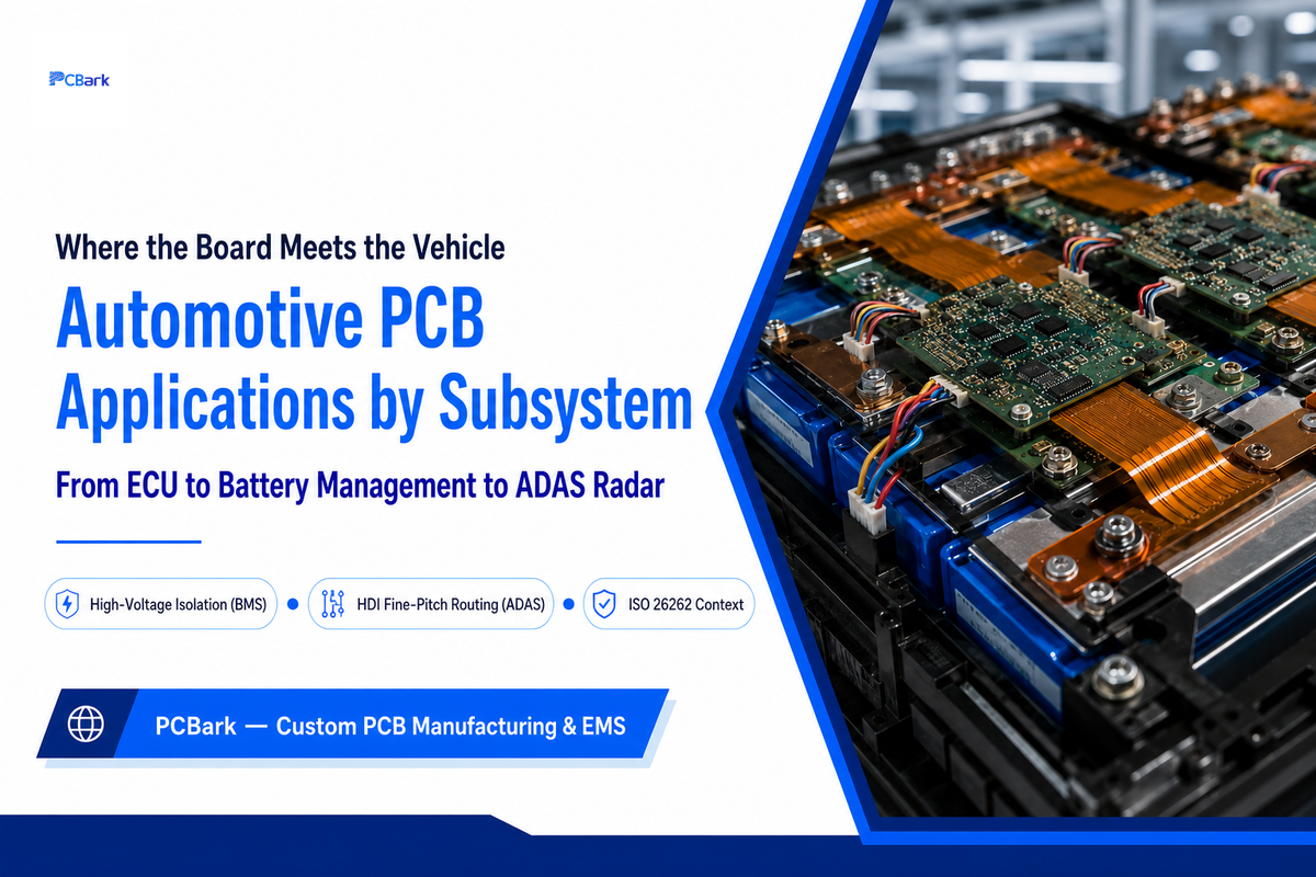
| Subsystem | Driving constraint |
|---|---|
| ECU / body control | Dense digital routing, moderate thermal load, long service-life reliability |
| ADAS (advanced driver assistance systems) domain controllers | HDI fine-pitch BGA routing, functional-safety traceability (ISO 26262 context) |
| Battery management (BMS) | High-voltage isolation, creepage/clearance spacing |
| LED lighting | Metal-core thermal dissipation |
| Infotainment | Standard multilayer, cost and density balance |
How Do Automotive PCBs Handle High-Voltage Requirements in Electric Vehicles?
EV high-voltage subsystems — battery management, onboard chargers, traction inverters — push board design past what the four families above were built for. The core response is creepage and clearance: wider spacing between high-voltage and low-voltage copper features than a 12V system needs, sized against the enclosure’s working voltage and pollution-degree assumptions, not a rule of thumb from a different voltage class.
At the 400V-class DC bus voltages common in EV traction systems, IPC-2221-style tables call for roughly 3.2mm to 6.4mm of spacing, depending on material and pollution degree, versus about 0.13mm to 0.4mm for a 12V accessory circuit sharing the same board. Slots, grooves, and isolation barriers are common ways to regain the board space that spacing costs.
This is also where the board-family boundary gets tested hardest at the substrate level: published research on high-power SiC traction-drive modules has found DBC ceramic substrates run into heat-spreading and manufacturing limits that IMS (insulated-metal-substrate) alternatives handle better under both steady-state and transient load — a materials tradeoff worth a dedicated conversation with your fabricator rather than a default assumption.
ADAS long-range radar deserves a separate mention: automotive radar operates at 76-81 GHz, a range where the four-family model stops applying; a radar board needs controlled-impedance, RF-grade laminate, not just a choice among rigid, flex, metal-core, or HDI. Material suppliers are responding directly to this: Rogers Corporation released its RO4830 Plus circuit material in February 2025, purpose-built for automotive radar applications. Please refer to our High-Frequency PCB guide or our Rogers PCB capability page if your program includes radar or any other high-frequency components.
Decision rule: If the core requirement of your subsystem is dense digital routing or rf signal integrity, make that constraint your first decision; pick your board family and material second. most of the common mistakes in this guide are based on making an initial board family selection before defining the driving requirement.
Automotive PCB Manufacturing, Assembly, and Design Technology
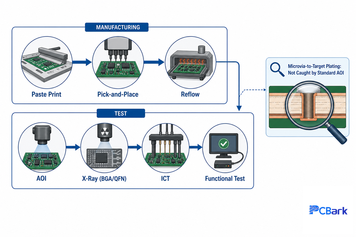
In a very superficial view of a automotive pcb manufacturing is quite conventional in that it proceeds from: paste print, pick-and-place, reflow, test. Standard test flow follows into Automated Optical Inspection (AOI), X-ray of hidden joints (BGA, QFN), In-circuit Testing (ICT), and real operating test conditions. Underneath that surface of our board process, though, what’s less apparent, but is important for our automotive boards, is a critical blindspot that traditional test doesn’t catch.
⚠️ Important
As highlighted by IPC, microvia-to-target-plating failures aren’t detected by standard IPC-6010 acceptance tests; that failure will only appear post-reflow, after ESS or out in the field. Instead, IPC has recommended electrical-resistance measurements be conducted with a test coupon as a replacement for or compliment to microsection/visual analysis. For any HDI boards with a microvia that are in a safety- or reliability-critical automotive application, you should inquire specifically if this resistance test coupon measurement is part of the test regime rather than just AOI and X-ray.
“Traditional inspection methods are no longer an effective quality assurance tool” for catching microvia-to-target-plating failures before boards leave the fabricator.
IPC, industry warning on printed board microvia reliability
2W
Thermal via threshold for dedicated via-to-plane path
300MHz
Approximate ceiling where the 20H EMI rule stays reliable
Board design review rule: if a component on the board has heat dissipation over ~2W, then before the first prototype run hot at tape-out check to ensure that a thermal via array routes to an internal copper plane; otherwise, a standard via arrangement should suffice, and a dedicated thermal study can be performed optionally.
An automotive-ready fab line typically enables a 0.1mm/0.1mm (4mil/4mil) trace and space on normal layers, a 0.2mm-6.5mm finished hole size, a 0.4mm-3.2mm thick board, and at least a 0.15mm annular ring on plated holes; a smaller geometry down to 0.075mm/0.075mm is available with HDI builds but will carry added cost and lead time, and should be specified only when layout necessitates it.
On the design side, some common rules of thumb that often circulate as universally applicable only really apply to certain frequencies, edge rates, or trace lengths; using them blindly will waste valuable board space without a proportional gain in EMI margin. Take the 20H rule, where copper pour is setback from the board edge to reduce EMI; it helps in an observable manner at frequencies below about 300MHz, but becomes unpredictable (and some times reverses at even higher frequencies). Not all nets will require 90-degree trace corners; this geometry only impacts controlled impedance traces electrically; a slow-edge-rate GPIO over a short trace doesn’t benefit from a 45-degree/arc trace and 50-ohm impedance control at all.
Vetting an Automotive PCB Manufacturer: A Buyer’s Checklist
In the automotive sector, whether a customer of pcb designers or Automotive, they often face the same challenge when evaluating an automotive circuit board supplier: there’s typically a lack of differentiation on a marketing page between true automotive pcb service and a consumer level shop which has just added the word “automotive” to their web site. The key difference between “consumer” and automotive-grade PCB performance-such as that required for ADAS, infotainment, or electric powertrain automotive components-is verifiable qualification rather than marketing words. Far and away the most common automotive circuit mistake is believing a logo on the homepage implies an underlying component AEC-Q200 certification report; a logo without the underlying reports means much less, particularly when the AEC-Q200 logo itself is confused with actual board-level qualification (see previous section).
- Obtain the AEC-Q200 component qualification test reports – not a component data sheet “grade number”.
- Verify against which revision of the IPC-6012 F/FA standard the fabricator’s process has actually been qualified – older “DA” revisions don’t count.
- Clarify the IATF 16949 certificate scope – an IATF certificate may cover only a single product line or facility rather than the entire site from which you intend to source the product.
- On HDI/microvia constructions, inquire whether trace resistance is measured for test coupon beyond standard AOI/X-ray inspection.
- When evaluating automotive pcb companies, qualifying automotive pcb manufacturers, or qualifying a single PCB manufacturer, apply the same automotive circuit design and qualification guide lines as detailed above prior to committing a purchase order.
- Confirm material and substance-declaration records for EU ELV restricted substances are available in the format your compliance team requires, not simply “assumed” from a general RoHS statement.
For automotive suppliers in particular, facility certification has become a practical hard gate, not just a nice-to-have. Suppliers to automotive OEMs providing any component to pcbs, not just electronics, are usually required to be IATF 16949 certified to be a qualified supplier. (Our company background lists our certifications in full, including IATF 16949, along with IPC-A-610 Class 2 & 3, ISO 9001/14001, UL, RoHS, REACH, and CE. See our automotive PCB capability page for specs and RFQ.)
Request an Automotive PCB Quote →
Industry Outlook: What’s Changing in Automotive PCB Sourcing (2026)

This outlook for the automotive PCB market centers on the impact of the standards and certification landscape on a buyer’s decision, not the overall growth forecast alone, because that landscape is what actually shapes the next RFQ. The search data behind this guide tells its own story: searches for “automotive pcb” sit flat at 70-140 a month with no clear trend, while “IATF 16949” draws more than 40 times that volume and “AEC-Q200” draws over 5 times it. That gap reflects a real shift already underway, qualification-proof research is moving earlier into the RFQ screening stage. Suppliers who can’t produce an AEC-Q200 component test report or a scoped IATF 16949 certificate by the RFQ stage are increasingly screened out before quoting even begins, not after.
There are two major developments driving this accelerating pressure. December 2025 marks the publication date for IPC-6012FA, so the actual automotive-specific specification for PCB quality has only been out a few months – and many of the competitive entries in the space haven’t yet caught up. Further out, the IATF 16949 standard is expected to be significantly revised with explicit requirements related to software quality and supply chain resilience in the next 12-18 months, added on top of the current quality management standard. Just as a direction indicator: overall, the automotive pcb market is estimated to be in the order of $10 billion globally in 2025, with a mid-single digit CAGR to mid-2030s.That information is useful, but this other point regarding qualifications is the one you really need to act on now.
This implies for the buyer today: Be proactive in requesting an AEC-Q200 component report, and verifying the exact scope of an IATF 16949 certificate prior to sending your designs to suppliers – make it a pre-RFQ filter rather than a closing stage step.
Frequently Asked Questions
Q: Can automotive PCB manufacturers produce boards for electric vehicles (EVs)?
View Answer
Yes, though EV power electronics — battery management, onboard chargers, traction-drive inverters — add requirements beyond standard automotive qualification. High-voltage creepage and clearance spacing is typically needed, and high-power SiC inverters often call for ceramic DBC or insulated-metal substrates instead of standard rigid or metal-core boards. A supplier building EV power electronics should show real experience with isolation-barrier design and substrate thermal performance, not just general automotive certification.
Q: Do automotive PCB manufacturers offer prototyping services?
View Answer
Most established automotive PCB fabricators run parallel prototype and production lines, since validating on real automotive-grade material and copper weight is what catches thermal and mechanical problems before a production run commits to tooling. Confirm the prototype uses the same qualified material stack as production — a cheaper substitute won’t expose the failure modes this guide covers.
Q: How are automotive PCBs tested for quality and reliability?
View Answer
A standard automotive test sequence includes AOI for visual defects, X-ray inspection for hidden solder joints under BGA/QFN parts, In-Circuit Testing (ICT) against the schematic, and functional testing at real operating conditions. Component-level reliability also draws on AEC-Q200 methods: temperature cycling (JESD22-A104), vibration and shock (MIL-STD-202). On HDI boards with microvias, ask whether resistance-coupon testing is also run — IPC has flagged that standard acceptance testing alone can miss microvia defects that surface later in the field.
Q: What is a sensor PCB?
View Answer
A sensor PCB hosts and conditions signals from automotive sensors — wheel-speed, pressure, or proximity sensors feeding ADAS and safety systems — and carries the same AEC-Q200 component and automotive-grade laminate qualification as any other underhood board in the vehicle.
Q: How do supply chain challenges impact automotive PCB production?
View Answer
Automotive PCB production sits downstream of raw-material supply (copper-clad laminate, high-Tg resins) and semiconductor availability, and either shortage alone stalls a build. Because IATF 16949 facility qualification and PPAP records are tied to a specific approved process and material set, a supplier can’t simply substitute an equivalent laminate or component mid-run without re-qualification — which is exactly why qualified automotive PCB capacity turns into a real bottleneck during supply shocks, more than flexible, faster-swapping consumer-electronics manufacturing typically experiences.
Q: Can a damaged automotive PCB be repaired?
View Answer
A cracked solder joint or a dead component is usually repairable, but conductive anodic filament (CAF) growth or internal delamination generally is not. Most OEMs specify replacement over field repair for safety-critical modules such as BMS or ADAS systems in service.
References & Sources
- IATF 16949:2016 OverviewAutomotive Industry Action Group (AIAG)
- IATF Global Oversight, Customer-Specific RequirementsInternational Automotive Task Force
- IPC-6012 Qualification and Performance SpecificationIPC International
- IPC-2152: Current-Carrying Capacity in PCBsANSI
- AEC-Q200 Rev. E Base DocumentAutomotive Electronics Council
- SAE J3083, Reliability Prediction from Field Return DataSAE International
- ISO 26262 Automotive Functional Safety WhitepaperSRM Tech
- Driving Reliability for Automotive ICs with Early Design AnalysisEE Times
- What Industry 4.0 Really Means for PCB Assembly in 2025 and BeyondEE Times
Related Articles
- Automotive PCB Manufacturing CapabilityRFQ and capability page for automotive-grade builds
- Automotive Industry Solutions at PCBarkindustry-specific manufacturing overview
- Ceramic PCB GuideDBC/AMB substrate selection for high-power modules
- High-Frequency PCB GuideRF/microwave board design for radar and connectivity
- Rigid-Flex PCB Capabilitybuild envelope for dynamic and folding assemblies
Why We Write This
Automotive PCB buyers deserve a way to verify qualification claims rather than take a certification badge at face value, which is why this guide was written — the AEC-Q200-covers-components-not-the-board distinction alone corrects a mix-up across most competitor content on this topic. Every standards reference here (IPC-6012FA, IATF Rules 6th Edition) was checked directly against IPC and IATF’s own published documents as of July 2026.
One minor note on terminology: the same qualification path applies whether a reader calls it an automotive PCB, a car circuit board, or an automotive printed circuit board, a single-sided PCB used in a simple sensor and a dense multilayer board used in an EV powertrain both fall under it. Automotive technology keeps advancing, but the automotive pcb solutions genuinely built for an automotive operating environment, not just marketed for it, are the ones with an AEC-Q200 and IATF 16949 paperwork trail behind them, whether that paperwork comes from circuit boards sold into the automotive aftermarket or from an OEM’s supplier pcbs for automotive production lines used in the automotive industry today. Solutions in automotive pcb manufacturing that skip that paperwork aren’t automotive pcb assemblies worth building a program around, regardless of what the automotive pcb design on paper claims. Across the many types of automotive pcb and types of automotive pcbs on the market — from a simple car pcb to a high-performance automotive pcb built for EV traction — automotive pcb materials and key manufacturing and assembly choices drive the reliability of automotive pcb builds far more than marketing copy does, and the role of automotive pcbs in vehicle safety systems is exactly why. Automotive pcb suppliers and automotive customers alike should treat circuit boards for the automotive environments they’re built for as one category, whether the application is basic or advanced automotive systems, and whether the pcbs in the automotive industry or pcbs for the automotive industry come from a domestic or overseas facility. Watching the global outlook for automotive pcb market direction and the ongoing evolution of automotive pcb technology, one thing stays constant across every wave of pcb technology change: the impact of automotive pcb qualification requirements on a buyer’s shortlist only grows, which is a bigger practical concern than the outlook for automotive pcb market size or the automotive pcb technology itself. Reviewed by the PCBark technical team.