Get in touch with PCBark Company


Updated July 2026.
The robotics pcb is the printed circuit board that transforms robot sensor data and software decisions into physical motion – and it must survive conditions a consumer board never sees. Motor vibration, joint-level heat, and duty cycles measured in years, rather than warranty periods, mean that a layout that work in a desktop appliance can fail in months inside a robot arm or an AGV chassis. This guide is for the engineer tasked with picking board construction, acceptance class, and coating for a particular subsystem, not for a general audience curious about what robots are made of.
A robotics pcb carries power, control signals, and sensor data among a robot’s microcontroller, motor drivers, and sensors, and must be engineered for constant vibration and thermal cycling standard consumer boards are never subjected to.
Quick Specs
| Layer count | 1–40+ (rigid / HDI / rigid-flex) |
| Min trace / space (HDI) | 2 mil |
| Build standard | IPC-A-610 Class 2/3 |
| Common solder alloy near motors | SAC305 (high-ductility) |
| Scope | Fabrication + SMT/THT assembly + sourcing + test, single quality system |
What Is a Robotics PCB? Boards by Robot Subsystem

A robot is never a single board, and there is no one type of PCB that covers every subsystem. PCBs for robotics typically spread across a main control system board, one sensor-fusion board, one or more motor-driver boards, one power distribution board, and, wherever a joint or robotic arm requires movement, a flex or rigid-flex interconnect.
Each is a printed circuit board, but design pressures differ on each board, and the single most common mistake made by teams new to robotics hardware is to treat them as interchangeable. Even a line-following bot and an industrial robotic arm use the same board categories; what changes is the intensity, not the list.
Planning a robotics PCB manufacturing program, from pcb etching through final test, by deployment class, rather than where on the robot a board happens to sit next to a motor, is more useful. This is because it directly informs the relevant vibration and duty-cycle stresses. Whether this is your first robotics project building a single PCB prototype or you’re scaling robotics PCB projects to full volume production, the considerations outlined below remain the same.
| Subsystem | Fixed industrial arm | Mobile AGV / AMR | Wearable / humanoid limb |
|---|---|---|---|
| Main control | Rigid multilayer | Rigid multilayer / HDI | HDI, weight-constrained |
| Sensor / vision | Rigid, short cable runs | Flex or rigid-flex | Flex, dynamic bend zones |
| Motor / joint drive | Rigid, heavy copper | Rigid-flex at wheel/steer joints | Rigid-flex, continuous flex |
| Power distribution | Rigid, 2–3 oz Cu | Rigid, battery-adjacent thermal | Rigid, space-constrained |
Note that “robotics PCB” isn’t a single part number, but rather a system design decision made once per subsystem. The layout, in terms of component placement shape and board outlines, is determined by the robotic arm or chassis that contains the subsystem. This document takes the reader through each of these design considerations in the order an engineer must make them: starting with the intensity of motion, followed by the interconnect, then compute density, the motor-driver electronics, environmental sealing, the acceptance class, and then sourcing.
The 3-Tier Motion Severity Framework
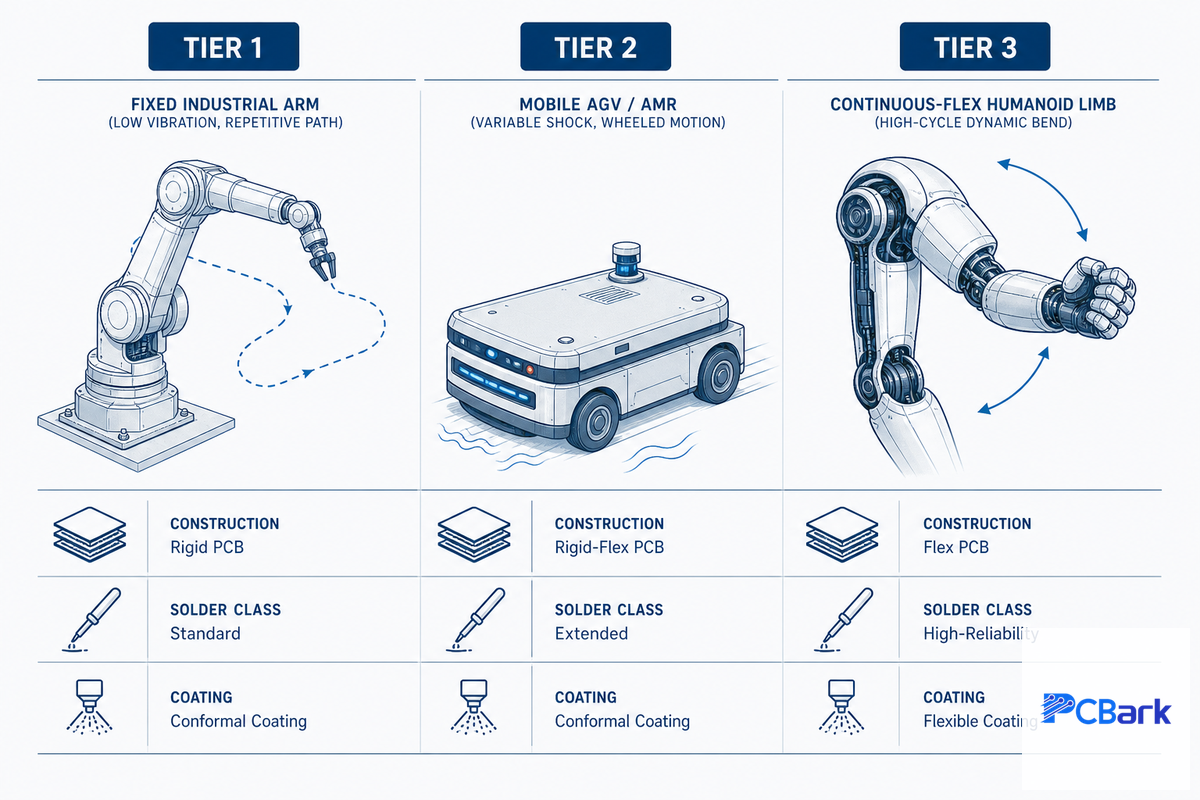
Prior to selecting any individual board, one must classify the level of vibration and duty-cycle stress the electronics in the deployment context will experience. We typically simplify this to three severity tiers, the first factor influencing board construction, solder alloy, acceptance class, and coating choice. Across the broad spectrum of robotic applications, factory automation cells, mobile platforms, or wearable exoskeletons, each falls into a distinct severity tier — this framework holds across nearly all applications of robotics we encounter.
| Tier | Subsystem | Construction | Solder / class | Coating |
|---|---|---|---|---|
| Tier 1, Fixed/repetitive (bolted industrial arm) | Main control | Rigid multilayer, 4-8 layers | Standard SAC alloy, Class 2 | Acrylic (AR) |
| Motor-driver | Rigid, 2 oz Cu | Standard SAC alloy, Class 2 | Acrylic (AR) | |
| Sensor / vision | Rigid, short cable runs | Standard SAC alloy, Class 2 | Acrylic (AR) | |
| Tier 2, Mobile/variable-shock (AGV/AMR) | Main control | Rigid multilayer or HDI | SAC305, Class 2/3 mixed | Silicone (SR) |
| Motor-driver | Rigid-flex at moving joints | SAC305 near motors, Class 2/3 | Silicone (SR) | |
| Sensor / vision | Flex or rigid-flex | SAC305, Class 2 | Silicone (SR) | |
| Tier 3, Continuous-flex/high-cycle (humanoid limb) | Main control | HDI, weight-constrained | SAC305 + underfill, Class 3 | Parylene (XY) |
| Motor-driver | Rigid-flex, dynamic bend zones | SAC305 + underfill/staking, Class 3 | Parylene (XY) or silicone | |
| Sensor / vision | Flex, dynamic bend, up to 200,000 cycles | SAC305, Class 3 | Parylene (XY) |
Our most common finding is over-specifying Class 3 acceptance and rigid-flex on every robotics program by default, that habit can add 10-30% in cost for a board that never sees constant flex. The opposite mistake is worse: treating a mobile AGV like a bolted-down Tier 1 arm and under-specifying solder and coating for a board that genuinely experiences variable shock loading every time the vehicle changes direction.
💡 Pro Tip
Use the robotics PCB type selector to cross-check your tier assignment against a specific subsystem before you lock a stack-up.
Joint & Limb Interconnect, Rigid-Flex Bend-Cycle Engineering
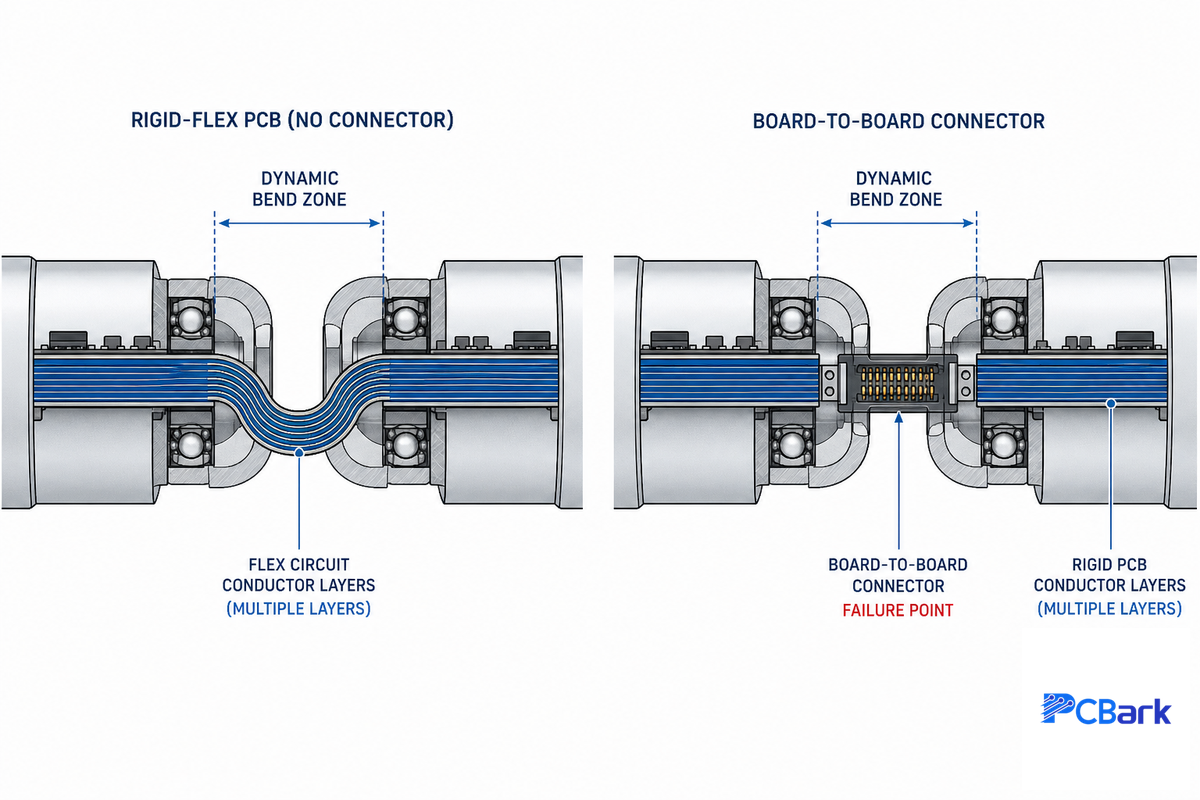
Once a subsystem crosses a moving joint, the question stop being “rigid or flex” and becomes “static bend zone or dynamic bend zone” – and the two have very different design rules. IPC-6013 draws that line explicitly: a qualification and performance specification for flexible and rigid-flex printed boards that governs construction for install-and-forget bends versus continuously flexing regions.
What’s the difference between rigid-flex and separate boards with connectors?
A static bend, a board folded once during assembly and never moved again, can usually run 10 to 20 layers on a rigid or rigid-flex construction with no special reliability planning. Dynamic bend zones, the kind that see continuous motion at a shoulder or wrist joint, need to be engineered down to two conductor layers, because every additional layer adds thickness and stiffness that fights the bend.
Engineers who design humanoid robot arms run into this constraint at nearly every joint. Rigid-flex earns its premium over a rigid board plus a board-to-board cable when the joint moves constantly: it removes the connector as a failure point and eliminates the weight and packaging volume of a discrete cable assembly. For a high-volume, cost-sensitive build where the joint motion is limited, a plain rigid board with a cable assembly can still be the cheaper and equally reliable choice – rigid-flex isn’t a default, it’s a decision made per joint. A 2024 sensors journal study using Taguchi design-of-experiments methodology tested five production variables against Interconnect Stress Test reliability and found conductive layer count and plating current density to be the two most influential factors – the optimum construction in that study was a two-layer polyimide laminate with 0.4 mm plated drill holes and 2 A/dm² galvanic current density, which lines up with the “keep dynamic zones thin” principle IPC-6013 is built on.[1]
Rigid-flex earns its place in mechanisms where a connector genuinely can’t survive the motion: a 2020 USPTO patent for a robotic surgical device uses a rigid-flex PCB specifically inside the instrument handle to control camera tilt and pan functions – exactly the kind of confined, continuously-articulated mechanism where a cable-and-connector approach would add bulk and a failure point the design can’t tolerate.[2]
📐 Engineering Note
Keep dynamic-flex zones at 2 conductor layers where possible. Static (install-and-forget) bends can run 10-20 layers on rigid-flex without a reliability penalty – the layer-count limit applies specifically to sections that flex continuously in service, not to the board as a whole.
Our multilayer flex pcb design guide covers generic flex stack-up questions such as how to control impedance, determine the appropriate via architecture and do the overall bend-radius math for a non-jointed flex run, as well as how to use a rigid PCB combined with flex jumpers on flexible substrates if a fully rigid-flex build is overkill for design for manufacturing, but we’ll stick to the decision regarding the joint motion in this guide.
Main Control & Sensor-Fusion Boards, HDI Density Decisions
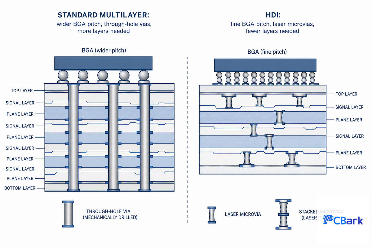
The primary control board for a robot will need to route an AI or motion-control processor, the inputs of sensor-fusion (IMU, LiDAR, camera), and an ever increasing number of high-speed data lines and communication interfaces to a footprint that’s always shrinking. This constant increase in density of functionality to form a robot will eventually drive the design to abandon standard multilayer and instead choose HDI construction.
| Signal | Standard multilayer OK | HDI required |
|---|---|---|
| BGA pin pitch | ≥ 0.8 mm | < 0.65 mm (fine-pitch AI/SoC packages) |
| Trace / space | 4 mil / 4 mil | 2 mil / 2 mil (microvia routing) |
| Layer count for equivalent routing | 8–12 layers | 4–6 layers (any-layer via structures) |
Using HDI with stacked microvias and laser drilled via-in-pad structures in lieu of mechanically drilled vias all over the board, is the way that every-layer-interconnect (ELIC) HDI construction provides enough functionality that it will fit a fine-pitch AI processor and multiple sensor interfaces onto a PCB that can be routed onto or within the confines of a robot’s head or torso while simultaneously limiting its layer count. Cost and lead time both increase for HDI construction, so this stackup design choice is a threshold decision, not a default: if the largest packaged device on your main control board is a BGA no finer than 0.8 mm pitch and your routing closes on standard 4-mil trace/space, standard multilayer is the right call and HDI is over-spec. Getting this wrong in either direction is expensive — over-specifying HDI when standard multilayer would route fine adds unnecessary cost and lead time, while under-specifying it on a genuinely fine-pitch BGA risks a routing failure that isn’t caught until first article, forcing a respin. PCBark’s CAM engineers run this threshold check as a standard part of DFM review before fabrication starts, precisely because a mid-program layer-stack change costs far more than getting the call right up front.
Signal integrity is another significant contributor to a board’s PCB layout work, with sensor-fusion inputs pushing high-speed data so rapidly that trace-length matching, differential-pair routing, and keeping components on the PCB properly spaced all become critical to keeping the data reaching the processor clean rather than corrupted. Crosstalk around a dense, fine-pitch BGA is controlled the same way it’s on any high-speed board, solid power and ground planes, controlled spacing between adjacent signal traces, and keeping the noisiest motor-driver traces on a separate layer entirely rather than routed alongside the sensor data lines.
Motor-Driver Boards, Thermal & EMI Design
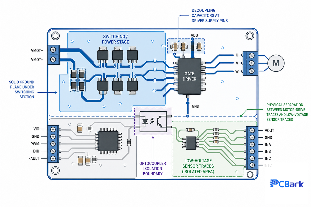
High-torque, low-speed demands at a robot’s joints, compared against the high-speed, low-torque output of an efficient servomotor, are mechanically mismatched, the drive electronics exist specifically to bridge that gap, and that bridging is where most robotics PCB thermal and noise problems originate.[3] Motor-driver boards are high-power PCBs by nature, and a high-power PCB on any robotics circuit board has to do two things at once: manage heat dissipation from the switching driver, and keep the PWM switching noise it generates away from the sensor and communication lines sitting a few centimeters away.
How do I calculate trace width for motor currents?
Standard traces are specified per IPC-2221 based on desired temperature rise over ambient; for a 4A continuous motor-driver, 1-oz copper, a 20C rise dictates a trace roughly 40-50 mils wide, not just a rough ‘leave it to the fabricator’ guess.
Double the width on internal copper to meet the same parameters, since internal copper lacks direct air cooling. Push that same 4A into 2 oz of external copper, and the required width is roughly halved; this is why motor-driver boards switch to heavier copper for layout, not narrower traces.
How can I reduce noise in my robot PCB from motors?
High-power motor-driver stages generate broadband electromagnetic interference from switching that’s coupled onto surrounding sensor and communication lines by improper board layout. Decoupling capacitors placed directly adjacent to each driver’s supply pin are the usual fix, minimizing this transient as it occurs on the switching section before it can travel through the plane; the effect becomes much more pronounced in high-current systems than in the low-power sensor world.
Standard design practices (solid grounding under the switching section, physical isolation of motor-drive signals from low-level signal lines, using differential-pair routing for high-speed signal lines) apply here, but arguably the most important decision the designer can make is to isolate the low-voltage control circuits from the high-current motor circuits. Using optocoupler isolation for both gate drive and phase current sensing is a no-wear, though bulkier, alternative to mechanical switches, and one optocoupler chip specifically optimized for this purpose reduces the motor-isolation’s PCB area requirements by roughly 35% versus previous options, while still providing the safety necessary for motor control.[4] Thermal stress on the solder joints adjacent to the motor is the other reliability concern here; analysis shows that thermal fatigue cracks propagate most readily from points near a heat source, so SAC305 solder joint material with higher ductility is preferred in this region rather than a standard SAC paste.[5] Avoid an all too common improper-design shortcut in real-time control layouts, placing a high-current motor trace directly alongside a low-voltage signal line simply to save board space. That voltage drop and associated noise will cost you far more in field service than a few millimeters of routing would have.
✔ Advantages of dedicated motor-driver boards
- Isolates switching noise from the main control board
- Simplifies thermal design (heat stays local to one board)
- Allows independent qualification per motor type
⚠ Limitations
- Adds a board-to-board interconnect (another potential failure point)
- Requires its own EMI-aware ground-plane strategy, not inherited from the main board
Environmental Protection, Conformal Coating Near Motors & Joints
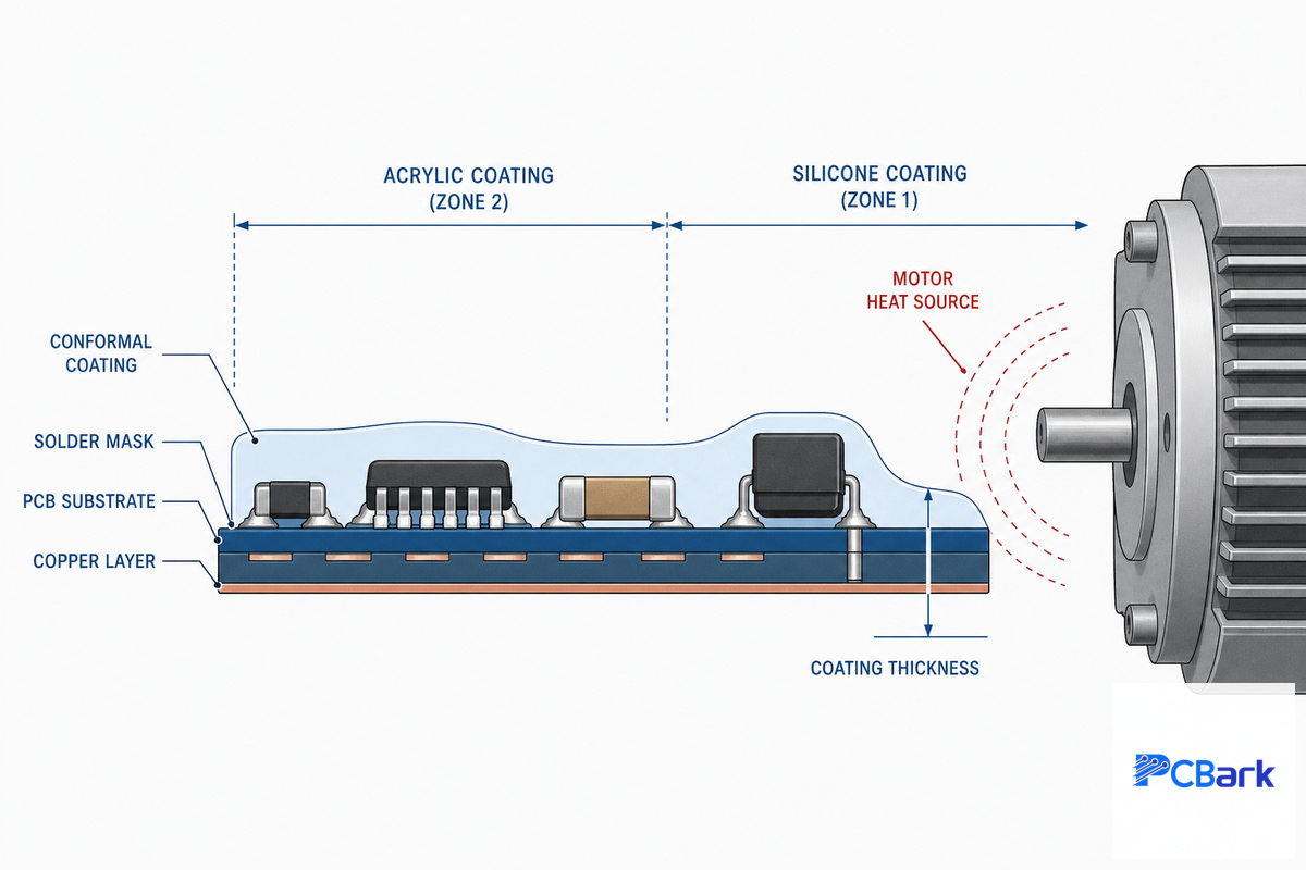
A robotics PCB generally doesn’t fail from a singular dramatic incident, but rather through gradual wear-out from the relentless accumulation of dust, moisture, and vibration on a few critically stressed connectors and solder joints over several years. Chemical compatibility of the conformal coating in close proximity to a motor, in terms of withstanding the motor’s thermal cycling without cracking or delaminating at any points of stress and flexure, is just as critical as how well it covers everything.
| Chemistry | Temp tolerance | Flex tolerance | Rework |
|---|---|---|---|
| Acrylic (AR) | Moderate | Low | Easy (solvent-strippable) |
| Polyurethane (UR) | Good | Moderate | Difficult |
| Silicone (SR) | Excellent (near-motor default) | Good | Moderate |
| Parylene (XY) | Excellent | Excellent (thin, conformal) | Very difficult (requires stripping) |
IPC-CC-830 is actually the specification that really governs this choice, detailing qualification and conformance criteria for electrical insulating compounds where each coating chemistry is qualified against a specific material revision (acrylic is currently qualified under revision C, epoxy against another). Adjacent to a motor, silicone is effectively a practical default simply because it retains its flexibility over the greatest temperature range of the four chemistries, acrylic is easiest to rework but holds up worst under frequent thermal cycles in the proximity of a heat source and therefore is a poor fit for precisely where boards adjacent to motors most require protection.
Acceptance Class Decision, IPC Class 2 vs Class 3 by Failure Consequence
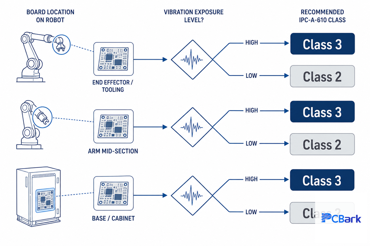
IPC-A-610 – at revision J and published in March of 2024 – is the industry’s acceptance specification for assembled boards, and defines a real, observable difference between Class 2 and Class 3 rather than a marketing tier.[6] One frequently cited visible distinction is solder wetting angle (roughly 180° for Class 2 versus 270° for Class 3), and Class 3 also mandates 100% inspection of critical features such as BGA voiding rather than the statistically sampling based approach used for Class 2.
Decision tree: which class does your robot actually need?
- If the failure of a board causes a robot to halt in a manner that carries no risk (for example, if an automated warehouse robot stops for service), Class 2 is the correct default.
- If the failure of a board can lead to an accident (e.g., a surgical robot, or an automated arm operating around people), use Class 3 with no exceptions.
- If the failure of a board is prohibitively expensive to repair or access once deployed (such as within a sealed humanoid joint or a system deployed sub-surface or in space), then Class 3 is the choice, driven by cost of access as much as immediate safety concerns.
To be entirely honest about what one receives for an investment in Class 3, many PCB fabrication resources will mention that even rigorous Class 3 inspection doesn’t guarantee a product will remain reliable indefinitely, since the inspection only addresses workmanship at build time, not fatigue induced over years of vibration. This is precisely why, regardless of your choice for acceptance class on your purchase order, the decisions regarding motion severity and solder-alloy mentioned previously in this guide play a role – Class alone is no replacement for appropriate design. Generally, specifying Class 3 without a clear need for safety or a cost-driven requirement to access the component after deployment adds 10-30% to assembly costs without yielding any significant benefit to your product.
Our IPC Class reliability selector allows you to make this same selection based on the input for your subsystem, and our certifications page provides evidence of the necessary credentials behind it.
Component Sourcing & Traceability for Robotics BOMs

Robotics BOMs load value into a few parts — motor-driver ICs, IMUs and application processors — that have been known to make ideal targets for counterfeit or re-marked components sourced through unauthorized distribution channels. AS5553-based sourcing discipline (buy only from authorized distributors, with lot-code traceability) comes into play because a discovered problem with a bad component costs more as it’s discovered later: caught at incoming inspection, it’s a rejected part; discovered after final assembly, it’s a full board rework; in the field, it means a service call and a warranty claim. While literature on the cost of quality discusses such escalating costs in terms of general manufacturing principles rather than a PCB-specific multiple, we would rather tell you what the risk profile looks like honestly than to assign an apparently precise-sounding number we can’t prove.
Practical implications for a robotics program: instruct your PCB assembly partner to buy all your motor-driver ICs and all sensor components only from authorized distribution — PCBark’s turnkey sourcing runs under the same ISO 9001 quality system as fabrication and assembly, so traceability doesn’t depend on a separate broker relationship — and to carry lot-code traceability back to the component lot level for every reel shipped, not just for the final board assembly. While teams designing PCBs for a first robotics program may consider component sourcing as a mere purchasing step, on a robotics BOM, it’s really a design decision taken during board design, not a logistics task at the shipping dock — and it’s worth double-checking it again at testing and validation prior to design lock, not afterwards.
Industry Outlook, What Rising Robotics Volume Means for Board Sourcing

At its most honest, the market-size estimation for the robotics industry can be found scattered across various reports, with estimates varying widely – from one firm that put the near-term (2025) humanoid robot market around $7.8 billion up to another predicting the 2028 market to be close to $13.8 billion. Estimates of the CAGR across this range from around 22% to 37%, depending on how scope and methodology are defined. This range alone is itself useful – for a customer to know not to get too fixed on a particular number, but not that the direction is otherwise in question — all forecasts show this sector is rapidly growing, and unit shipments paint the same picture.
The bottom line for buyers now, before the precise contours of this expanding market wave take shape: qualify your second-board source for your largest-volume robotics sub-assemblies, ideally before you’re under extreme time pressure. That risk is concrete, not hypothetical — a fabricator still building up IATF 16949 process control and lot-code traceability for the first time is precisely the one that turns a scheduled ramp into a multi-week requalification delay, right when you’re running most of your order volume, because a new vendor can’t simply inherit a proven process recipe. Programs that already run under that discipline, and that hold suppliers to current acceptance standards like the current IPC-A-610 revision, can transition from low volume to mass production with the existing vendor without re-qualification. As robotics technology matures across production robotics systems, PCBark builds every program on that same documented process from first article onward, which is why we see the value in second-board qualification for motion-control and power-management boards — main control and motor-driver — well before the more-basic power-distribution boards need it.
We size motor-driver copper and pick solder alloy from the deployment class before we ever look at the acceptance-class line on the purchase order – the class only tells us how it gets inspected, not whether it was built to survive the joint it’s going into.
PCBark Robotics Program Engineering Team
Frequently Asked Questions
Q: What is a PCB in robotics?
View Answer
In robotics, a PCB is the board that physically connects a robot’s microcontroller, sensors, motor drivers, and power supply so they can operate as one coordinated system.
Depending on the subsystem, it may be a rigid multilayer board, an HDI board, or a rigid-flex board built to survive a moving joint – there isn’t a single universal robotics pcb, only the right board type per subsystem.
Q: Why is thermal management important in robotics PCBs?
View Answer
Motor drivers and AI processors concentrate heat in a small board area, and that heat accelerates solder-joint fatigue at exactly the joints already stressed by vibration.
Thermal vias, copper pours, and metal-core construction move heat away from switching components before it degrades nearby solder joints over the robot’s service life.
Q: What are the specific considerations for robotic PCB manufacturing?
View Answer
Beyond standard fabrication, robotics manufacturing has to account for vibration-tolerant solder alloy near motors, conformal coating chemistry matched to thermal and flex exposure, acceptance class matched to failure consequence, and traceable component sourcing for parts that are common counterfeit targets.
Getting any one of these wrong tends to show up months into deployment, not at first-article inspection.
Q: Where are PCBs used in robotics?
View Answer
Every functional block of a robot depends on a PCB: a main control board runs the processor and motion-control logic, sensor boards interface cameras/IMU/LiDAR, motor-driver boards regulate current to servos and actuators, a power-distribution board manages battery and voltage rails, and – anywhere a joint or limb needs to bend – flex or rigid-flex boards carry signals across the moving section without a connector at the joint itself.
A humanoid robot typically uses several of each type across its head, torso, arms, and legs rather than one board type throughout.
Q: What should you look for in a robotics PCB manufacturer?
View Answer
Look past a single “lowest quote” and check for four things: documented IATF 16949 or equivalent process control (evidence they build to a repeatable recipe, not a one-off), in-house fabrication and assembly under one quality system rather than a broker relationship, authorized-distributor sourcing with lot-code traceability for your motor-driver and sensor ICs, and a named engineer who can walk you through a DFM review before your first article is built – not a ticket queue.
Any supplier that can show all four scales from prototype to volume without a re-qualification cycle; one that can’t will cost you the schedule slip exactly when your order volume is growing.
Q: How many control PCBs does a robot need?
View Answer
There is no fixed number – it scales with the robot’s subsystem count, not a standard.
A simple AGV may run on one main board plus one motor-driver board; a humanoid can use a dozen or more boards across its head, torso, and limbs.
Why We Write This
PCBark builds robotics pcbs as rigid, HDI, and rigid-flex construction under one IATF 16949 quality system, and this guide shows subsystem decisions the engineers actually discuss in a DFM review-including the market data issues we decided not to paper over in the outlook section. A well-designed PCB for a robotics program starts with these tier and subsystem decisions, not a part number. Reviewed by the PCBark technical team.
References & Sources
- Impact of Manufacturing Process Stages on the Reliability of Flexible Printed CircuitsSensors (MDPI), via PMC/National Institutes of Health
- U.S. Patent US10,806,538 B2, Robotic Surgical Devices, Systems, and Related MethodsUSPTO, via Google Patents
- IPC-6013, Qualification and Performance Specification for Flexible/Rigid-Flex Printed BoardsIPC International, Inc.
- Designer’s Guide to High-Performance Motor Control for RoboticsEDN / AspenCore Network
- Same source as above, motor-driver isolation component data (Renesas photocoupler PCB-area reduction)
- Thermal Cycling Life Prediction of Sn-3.0Ag-0.5Cu Solder Jointsvia PMC/National Institutes of Health
- Acceptability of Electronic Assemblies (IPC-A-610J-2024)American National Standards Institute (ANSI)
- IPC-CC-830, Qualification and Conformance Requirements for Conformal CoatingsIPC International, Inc.
- IPC-A-610, Acceptability of Electronic AssembliesIPC International, Inc.
Related Articles
- Robotics PCB Manufacturing & Turnkey Assemblyfull capability overview, calculators, and quote request for robotics programs
- Multilayer Flex PCB Design Guidestack-up, impedance, and via architecture for flex circuits generally
- Industrial Control PCB Guideruggedization and conformal coating for 24/7 industrial control boards
- Medical PCB Design Guidecompliance-driven design for medical and surgical robotics electronics
- Aerospace PCB Design Guidematerials and class selection for commercial aerospace boards
- Drone PCB Solutionslightweight HDI and flex construction for another weight-constrained, high-vibration platform




![16-24 Layer PCB: Stackup, Lamination & Design Guide [2026]](https://pcbark.com/wp-content/uploads/2026/07/16-24-layer-pcb-guide-featured-2-150x150.png)