
Get in touch with PCBark Company


![Rigid Flex PCB Design: Aerospace & Compact Devices [Guide]](https://pcbark.com/wp-content/uploads/2026/08/rigid-flex-pcb-design-featured.png)
Updated August 2026.
Rigid flex PCB design is an electromechanical process that treats the mechanical envelope, flex duty, stackup, routing, fabrication, assembly, and verification plan as one system. Layout is only one element. This guide explains how to define interfaces early, ask a fabricator direct questions, and release evidence instead of assumptions.
Quick answer: Rigid-flex PCB design replaces separate boards and cable interconnects with rigid component areas joined by integral flexible sections. Choose it when packaging, interconnect control, or installation repeatability creates more system value than the added fabrication and verification work.
Quick Design Brief
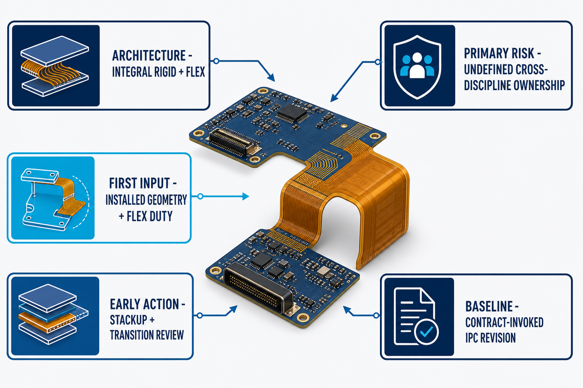
- Architecture: rigid sections and flexible regions with integral interconnects
- First Design Input: installed geometry and flex duty, not an assumed stackup
- Primary Release Risk: an undefined interface between mechanical, electrical, and manufacturing ownership
- Standards Baseline: Confirm the contract-invoked version of IPC-2223 and IPC-6013 with both project and supplier.
- Best Early Action: Hold a stackup and transition review before dense routing commences.
Key Takeaways
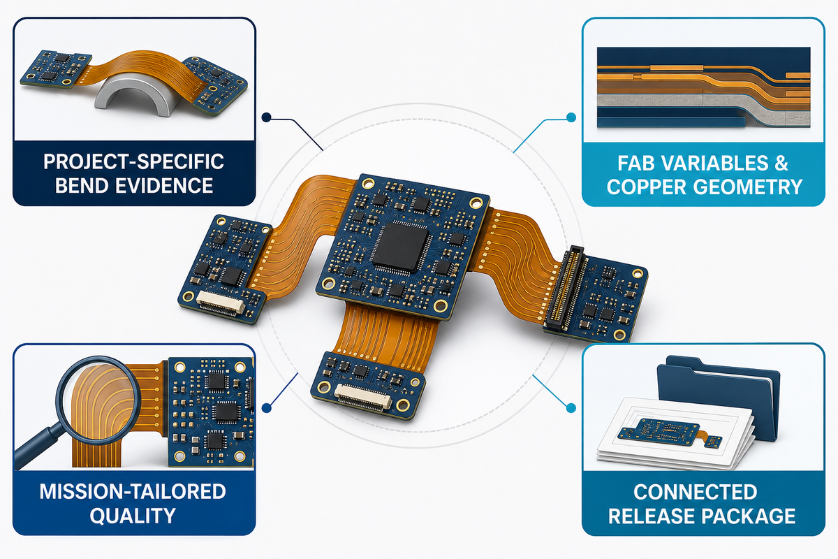
- A bend rule from another project isn’t evidence for your build.
- Flex reliability depends on fab variables and copper geometry.
- Tailor aerospace quality to mission criticalities and contractual acceptance criteria, consistent with NASA’s public risk-based quality guidance.
- Release package must link installed geometry, stackup, transition controls, inspection, and test.
What Is Rigid-Flex PCB Design, and When Is It the Right Architecture?
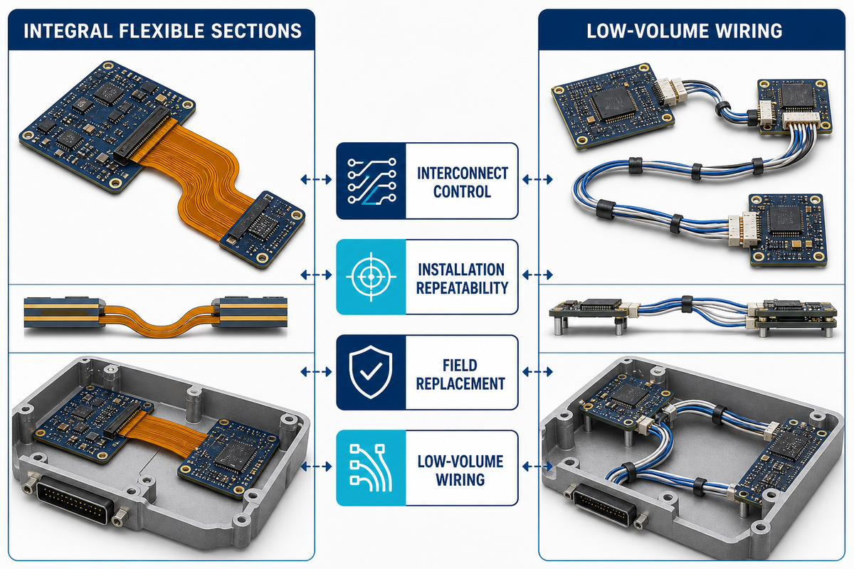
Rigid-flex PCB design is the engineering of one printed-circuit structure with rigid and flexible regions for component support and interconnection. It is the right architecture when removing board-to-board connectors, reducing cable-routing variation, or folding electronics into a constrained enclosure creates system value that offsets added board complexity. Use the brief above to frame this architecture choice before stackup or routing begins.
Rigid-flex printed circuit boards are not two circuit boards with a flexible cable added later. Copper, dielectrics, coverlay, stiffeners, plated features, and transition geometry are planned as one build. IPC-6013E’s public scope includes single-sided, double-sided, multilayer, and rigid-flex multilayer constructions, as well as stiffeners and several via types. That scope establishes categories; it does not select a construction for a specific product.
When should engineers choose rigid-flex instead of separate boards and cables?
Choose rigid-flex after careful evaluation of the total assembly, not just the bare board cost. Separate-board designs may have a lower bare-board cost while adding connectors, cable procurement, manual routing, extra inspection points, and installation variation. Rigid-flex is attractive when those system burdens are material.
It is less attractive when field replacement, frequent architecture changes, or simple low-volume wiring dominates the decision.
| Decision type / input | Rigid-flex gains value when… | Separate boards and cables retain value when… | Limitation / not suitable for |
|---|---|---|---|
| Installed volume | Folded geometry removes connector clearance | Enclosure space is available | Envelope not frozen |
| Interconnect count | Integral conductors remove mating pairs | Few simple links are needed | Interfaces change often |
| Assembly labor | Cable routing is variable or hard to inspect | Wiring work is short and accessible | No installation fixture plan |
| Service model | Module replacement is acceptable | Cables need independent field replacement | Repair boundary is undefined |
| Mechanical motion | Motion is defined and validated | Uncontrolled twisting may occur | Duty profile unknown |
| Procurement | One qualified build replaces several items | Multiple sources must be interchangeable | Supplier capability unreviewed |
| Test access | Access can be designed into rigid regions | Connectors provide convenient isolation | Fault isolation plan absent |
| Change rate | Architecture is stable before tooling | Prototype wiring changes weekly | Late enclosure revisions expected |
| Cost basis | Total installed cost is the comparison | Bare-board price is the true constraint | Labor and yield omitted |
Terminology check: Treat common labels as review prompts, not construction approvals.
| Term heard in a review | Precise use | What still needs confirmation |
|---|---|---|
| Traditional rigid PCBs | Traditional rigid circuit board design without integral flex | Connector and cable interfaces |
| Flexible PCBs | Flexible printed circuit boards or flexible circuit boards without rigid islands | Stiffeners, terminations, and duty |
| Flex and rigid-flex PCBs | A broad flex and rigid-flex PCB category | The actual construction type |
| Standard rigid-flex | A shorthand label, not a universal stackup | Supplier-qualified details |
| Advanced rigid-flex | Complex rigid-flex requirements expressed as a market label | Drawings, tests, and acceptance evidence |
| Multiple rigid islands | Multiple rigid areas joined by two flex regions or more | Whether overlapping flex regions occur in the installed shape |
| PCB technology | Rigid-flex technology, flex technology, and circuit technology are category terms | Materials and process capability |
| Stackup configurations | The number of flex layers and rigid layers in each region | Thickness, copper, and transitions |
| Design process | Design considerations, design tips, and design resources organized as questions | Supplier decisions and evidence |
| Flex solutions | Options considered before you design a rigid-flex board | Whether a complex design adds system value |
| Rigid and flex | A combination of rigid and flexible sections | Where each rigid and flexible region begins |
| Bend or flex | Motion language that must name direction and duty | Installed geometry and validation |
Place the enclosure model, connector list, assembly sequence, flex event, test strategy, and service boundary on one review page. If no one can name the line item rigid-flex removes or controls, the integration has no defined system benefit.
Key takeaway: Approve rigid-flex as a system architecture before treating it as a board technology.
Start With the Mechanical Envelope and Flex Duty Cycle
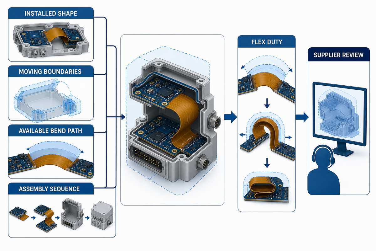
The mechanical envelope should define the installed shape, moving boundaries, available bend path, fastening points, and assembly sequence before the electrical team commits to transition locations. Flex duty then separates a one-time installation fold from repeated motion, because those conditions require different evidence, routing decisions, and qualification plans.
Begin with actual geometry. Export the enclosure surfaces, mark rigid-board datum points, record which side of the flex faces inward, and show the installer’s hand path. A nominal centerline is not enough when a housing edge, fastener, foam pad, or battery can force the flex into a smaller local curve or add torsion. Drawings should also state whether a bend is formed once, moved during service, or cycled during normal operation.
How should a bend radius be selected?
No universal minimum bend radius fits every rigid-flex PCB stackup. Bend selection depends on total flex thickness, copper type and weight, layer count, conductor orientation, coverlay system, bend angle, forming method, motion profile, and the supplier’s qualified process. The public IPC-2223 owner page establishes the design-standard scope but does not publish a universal value for a project-specific construction. Ask the fabricator to approve the proposed construction and installed geometry together, then verify the relevant duty condition.
A rigid flex PCB design example or rigid flex PCB design calculator can organize review questions, but neither establishes safe values for a project-specific construction and duty.
The Flex-Duty Evidence Ladder
- Define: installation-only, service movement, or dynamic operation.
- Model: installed path, bend direction, nearby contacts, and strain concentration.
- Approve: supplier-reviewed stackup, transition, copper, and coverlay details.
- Build: representative coupons or assemblies from the intended process.
- Verify: test to the program’s actual motion and environment, with acceptance criteria set before test.
Consider a sensor module that folds during final enclosure assembly and remains fixed in service. Calling it “dynamic flex” would drive the wrong test plan; calling it “static” without considering rework would also miss real handling. A correct duty statement records the production fold, permitted rework events, bend direction, installed restraint, and inspection point. A different device that opens on every use needs a cycle profile and representative moving assembly. Board outlines may look similar, but the evidence burden is not.
Software-neutral worked example: For the fixed sensor module, first freeze the enclosure and installation path; next classify the production fold and permitted service movement; then ask the fabricator to approve the proposed stackup and transition; after that, build a representative assembly; finally, verify the installed condition against acceptance criteria defined before test. This sequence works in any layout tool because each decision is tied to geometry, ownership, and evidence rather than a generic calculator value.
Key takeaway: A bend value is an output of construction and duty review, not a reusable input copied from a generic calculator.
Build the Stackup Around Materials, Bend Zones, and Transitions
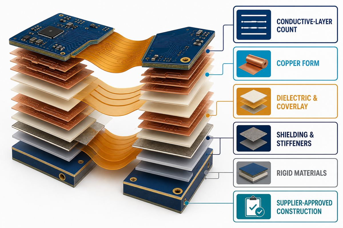
With the bend path and flex duty defined, a rigid-flex stackup should be built from the flex function outward: choose conductive-layer count, copper form, dielectric and coverlay families, shielding, stiffeners, and rigid materials with the supplier. Flex and rigid-flex material selection then needs a manufacturable boundary that supports bending without turning the rigid edge into a strain concentrator.
Use this process as rigid flex PCB design guidelines, then ask the supplier to confirm a rigid-flex PCB stackup and rigid-flex PCB material set for the actual build.
IPC’s public IPC-2223 owner page describes the standard as working with IPC-2221 and covering flexible-board design, component mounting, interconnecting structures, insulating films, dielectrics, and metallic materials. Use the licensed document invoked by the contract for actual design requirements. A public product description cannot replace its tables or supplier process limits.
Material names alone do not define a stackup. Polyimide constructions can differ in adhesive, copper, dielectric, coverlay, reinforcement, and lamination sequence. Those choices affect bending, dimensional behavior, plated features, impedance, and the rigid-to-flex boundary. For construction context, see PCBark’s guide to multilayer flex PCB construction.
| Stackup input | Question to resolve | Release evidence |
|---|---|---|
| Flex layer count | Which circuits truly need to cross the bend? | Net allocation and approved stackup |
| Copper construction | What does the duty profile require? | Supplier material callout |
| Dielectric family | Which electrical and mechanical properties matter? | Controlled material set |
| Coverlay | Where are openings and registration limits? | Coverlay artwork and notes |
| Stiffener | What load or connector interface does it support? | Material, thickness, and attachment definition |
| Shielding | How will shielding affect flexibility and grounding? | Shield construction and termination |
| Rigid material | What thermal and electrical limits govern it? | Approved material callout |
| Transition | Where does thickness change and strain collect? | Dimensioned zone and supplier sign-off |
| Impedance | Which regions require controlled geometry? | Region-specific model and coupon plan |
A 2025 flexible-circuit study indexed by the Directory of Open Access Journals examined five production factors at two levels. Its tested best variant used two conductive layers, a 100 μm polyimide laminate layer, a 0.4 mm plated-hole diameter, and 2 A/dm² bath current density. Study results identified conductive-layer count and bath current density as the most influential tested factors. Those values describe that experiment, not a universal recipe; the broader lesson is that board reliability depends on process controls as well as layout geometry.
Key takeaway: Freeze materials and transitions with the manufacturer before using the stackup as an electrical-model input.
Route Traces, Vias, and Return Paths Across Moving Boundaries
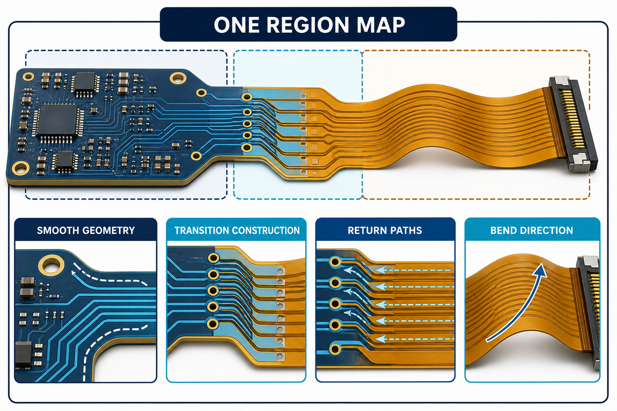
Routing across a flex region should keep mechanical strain predictable while preserving electrical continuity. Place bend-sensitive geometry, reference-path changes, vias, pads, openings, and copper-density transitions only after the stackup and duty are understood. Electrical and mechanical rules must be reviewed on the same region map rather than in separate checklists.
Conductors crossing a bend need a path consistent with the intended bend direction, smooth changes in geometry, and room for the supplier’s transition construction. Abrupt copper-width changes, dense copper next to sparse copper, coincident features across layers, and poorly placed openings can shift strain into a small area. The public scope of IPC-2223 includes flexible-board design and interconnecting structures, but the exact restrictions remain construction-specific and must be defined with the fabricator.
Return paths deserve equal attention. A high-speed signal entering a flexible section may encounter a different dielectric, plane pattern, shield, or spacing rule. Treat launches and transitions as one channel. PCBark’s page on high-speed PCB design adds context, but the model still needs the supplier-approved build.
- Partition first: keep components and test pads in rigid regions unless the supplier and mechanical design support another choice.
- Map all transitions by showing material, copper, impedance, and restraint changes on the same view.
- Review whether each via belongs in a rigid area, transition-control area, or approved flex construction.
- Check reference continuity by modeling the signal and return path across every region boundary.
- Inspect the installed shape because flat artwork cannot reveal enclosure contact or torsion.
A compact radio can pass a flat-board electrical review yet fail its packaging intent if the flex exit forces the signal bundle around a battery corner. Moving one rigid-board edge may provide a cleaner bend path than trying to “fix” the flex with tighter routing. That mechanical change can also shorten the channel and create room for controlled transition geometry. The lesson is practical: a routing review without the enclosure is incomplete, and an enclosure review without current artwork is equally weak.
Key takeaway: Route the signal, its return path, and its mechanical strain path as one interface.
How Do Aerospace Constraints Change the Design?
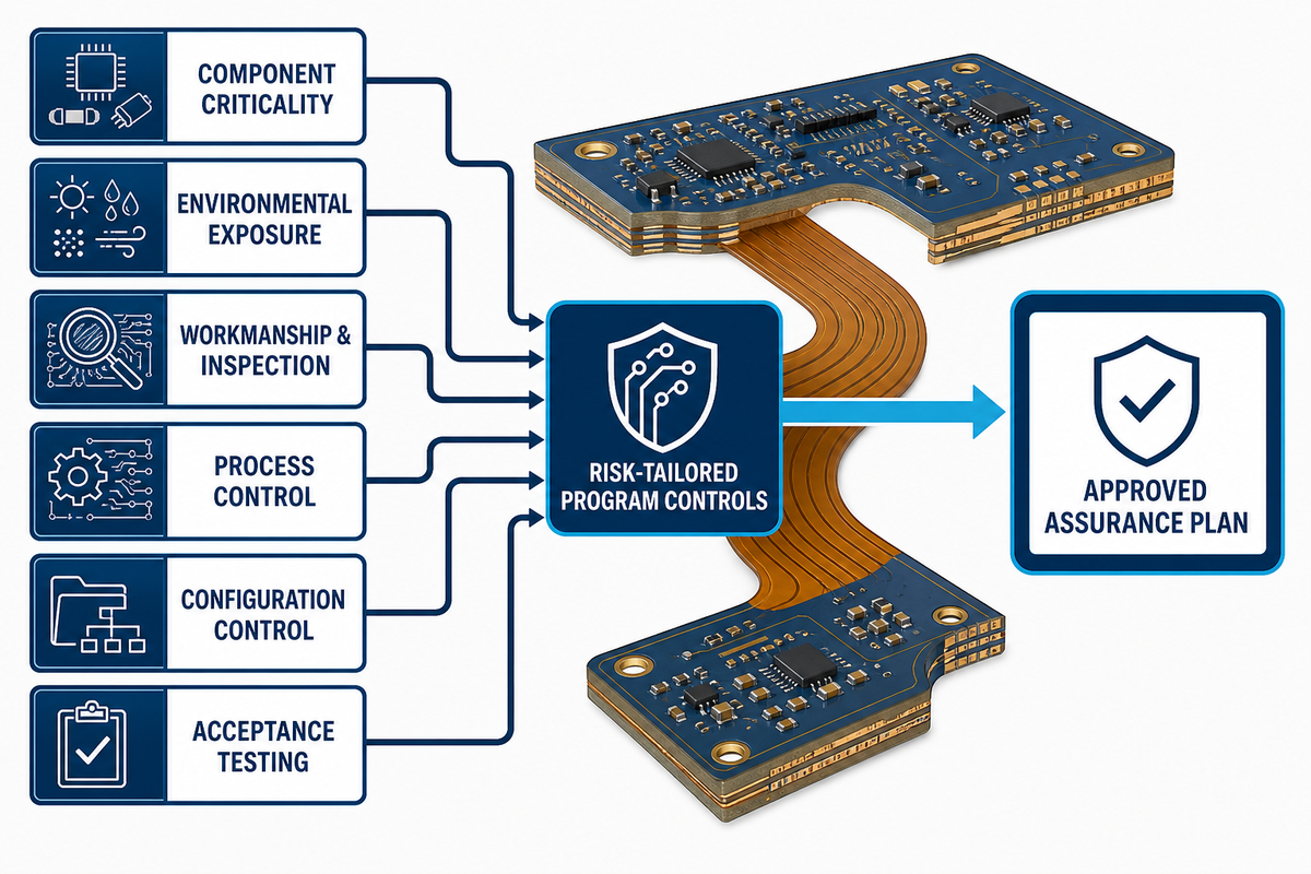
Aerospace constraints move rigid-flex design from general manufacturability toward mission-tailored evidence. This extends the prior signal, return-path, and mechanical-stress review into program evidence. Program teams must connect component criticality, environmental exposure, workmanship, inspection, process control, configuration control, and acceptance testing to the specific program. “Aerospace grade” isn’t a substitute for contract language, invoked standards, or an approved assurance plan.
NASA’s public quality guidance describes a risk-based program that considers mission and component criticality together with the likelihood and severity of noncompliance. It also says programs tailor quality-assurance resources for critical items and processes. That principle is a better starting point than automatically declaring one IPC class, one test sequence, or one certification for every flight-related assembly.
“Quality means compliance with descriptions of intent.”
Rigid-flex intent crosses files: form and fit in the enclosure model, workmanship in drawing notes, motion in a test plan, and material controls in procurement. Release review must confirm that those descriptions agree and reach the supplier as one controlled set.
The Mission-to-Enclosure Trade-off Ledger
| Trade-off axis | Aerospace emphasis | Compact-electronics emphasis | Limitation / not suitable for |
|---|---|---|---|
| Failure consequence | Mission consequence and criticality | User impact and warranty exposure | No approved severity model |
| Environment | Program-defined combined conditions | Use and storage profile | Exposure not measured |
| Mass and volume | Budgeted against reliability evidence | Often a primary packaging driver | No assembly-level comparison |
| Traceability | Lot, material, process, and inspection records | Risk-appropriate production records | Record retention undefined |
| Change control | Formal configuration baseline | Faster revisions with controlled equivalence | Silent material substitution |
| Inspection | Critical features tied to acceptance | Yield and defect containment | No measurable criteria |
| Test | Mission-tailored qualification and acceptance | Product-use and production-screen needs | Test not tied to failure mechanism |
| Supplier change | Approved process and equivalence evidence | Qualified alternatives where needed | Construction transfer untested |
| Repair | Program-approved disposition | Service and depot economics | Repair method changes flex geometry |
A paper available through NASA’s Technical Reports Server describes an application of rigid-flex electronics for shape-changing robots in constrained, moving geometry. It does not set universal limits for other vehicles or payloads. Ask about vacuum, contamination, radiation, vibration, thermal cycling, and outgassing only when the mission or contract requires it.
PCBark’s page for a commercial and civil aerospace PCB program handoff is the application link for teams preparing a supplier discussion. This guide does not imply controlled-defense eligibility, AS9100 certification, or spaceflight qualification; confirm every program-specific capability and contract requirement directly. A broader aerospace PCB design guide covers system-level issues beyond the flex architecture.
Key takeaway: Translate mission risk into controlled features and evidence; don’t turn a market label into an unsupported qualification claim.
Design for Compact Electronics Without Trading Away Assembly Access
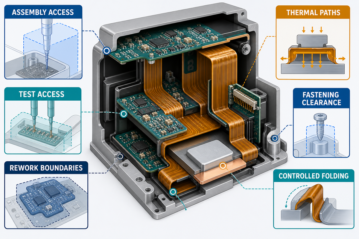
Compact electronics benefit from rigid-flex when folding removes connectors and lets rigid component islands occupy available enclosure surfaces. At this scale, the same mission-risk discipline becomes product-risk evidence. The public IPC-6013E product description confirms that rigid-flex multilayers and stiffened constructions fall within its scope, but it does not resolve assembly access for a particular enclosure. Packaging density still needs assembly access, test access, rework boundaries, thermal paths, fastening clearance, and controlled folding. A smaller board outline can produce a worse product if operators cannot assemble or inspect it consistently.
Start the compact design with a digital assembly rehearsal. Move the board from its delivery state into the enclosure, then add fixtures, fasteners, batteries, displays, heat spreaders, and cable-free rigid islands in the real sequence. Record where hands or tools need access. The design should prevent reverse folding and limit loads on solder joints, stiffener edges, and transition zones.
A handheld instrument may appear to need three small rigid boards because each face carries a different control or sensor. One rigid-flex assembly can remove two mating interfaces, yet it also couples all three islands into one replacement unit. If the display is the common service item, the integrated architecture can raise repair cost. A useful review therefore compares connector removal, assembly minutes, inspection access, replacement boundary, and expected revision rate rather than celebrating the smallest folded volume.
- Ensure enough board space is preserved in the rigid area for access to boundary scan, functional test interfaces and in-system programming.
- Prevent strain on solder joints and their associated components by providing clearance from the fold line, and keep bodies of components away from folding fixtures or contact with the enclosure.
- Define shipping and work-in-process shapes so the flex area is not damaged before installation.
- Show polarity, fold direction, and island identity without relying on an operator’s memory.
- After folding, verify that the thermal interfaces remain seated as intended.
When should you not use rigid-flex?
Avoid committing to rigid-flex while the enclosure, connector map, or service boundary changes frequently. Separate cables may be the better choice when independent field replacement matters, when uncontrolled twisting cannot be constrained, or when the program cannot fund representative build-and-test evidence.
A simple cable can also make early prototypes easier to change. The honest comparison is not “advanced board versus old wiring”; it is a controlled integrated assembly versus a modular interconnect architecture. Choose the one whose risks your team can define, manufacture, inspect, and maintain.
Key takeaway: Protect test, assembly, and service access as design inputs, not leftovers after packaging.
Rigid-Flex Interface Atlas: 5 Zones to Check Before Layout Release
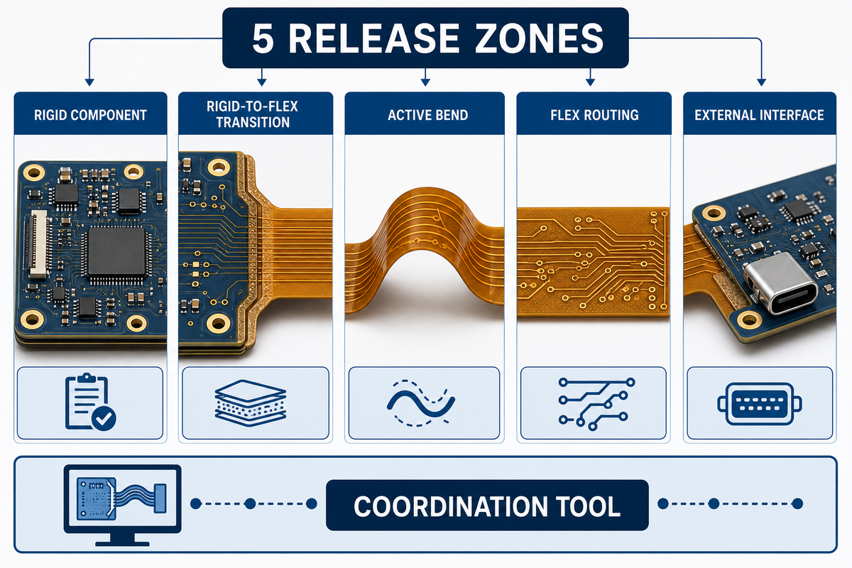
The Rigid-Flex Interface Atlas divides the assembly into five release zones: rigid component, rigid-to-flex transition, active bend, flex routing, and external interface. It turns the earlier test, assembly, and service-access concerns into release checks. Each zone receives its own owner, failure question, evidence item, and release check. The atlas is a coordination tool, not a validated life-prediction model or a replacement for engineering analysis.
Most design rules are attached to objects: traces, vias, pads, openings, or components. Failures often emerge at interfaces between object types and engineering teams. A zone map makes those handoffs visible. Put it beside the enclosure model and stackup at each review, then close every row with evidence or a named open action.
| Zone / check | Primary question | Evidence before release | Limitation / not suitable for |
|---|---|---|---|
| 1A Rigid / placement | Are components clear of folding and restraint? | Assembly model and courtyard review | Enclosure absent |
| 1B Rigid / test | Can production reach required nodes? | Fixture concept and test-point list | Test strategy pending |
| 2A Transition / materials | Where does construction thickness change? | Supplier-approved section view | Generic stackup only |
| 2B Transition / strain | What prevents the rigid edge from carrying the fold? | Installed-path review | Fold line uncontrolled |
| 3A Active bend / duty | What motion must the build survive? | Approved duty statement | Cycle profile unknown |
| 3B Active bend / routing | Does copper follow the intended bend? | Mechanical-electrical overlay | Stackup not frozen |
| 4A Flex route / signal | Is return-path continuity understood? | Region-specific channel review | Plane model missing |
| 4B Flex route / contact | Can hardware rub or pinch the flex? | Clearance and tolerance review | Tolerance stack absent |
| 5A Interface / assembly | Can operators install without overload? | Work instruction and fixture trial | No representative build |
| 5B Interface / acceptance | How is conforming hardware recognized? | Measurable inspection and test criteria | Pass/fail undefined |
The cited experiment reported production variables, including bath current density, that changed results. Results don’t validate the five-zone map as a failure model; they illustrate why material and process teams should be involved in release review. Likewise, the public scope of IPC-6013E can identify the relevant qualification document, but contractual criteria and project evidence still control acceptance.
Quotable rule: A rigid-flex design is released at its interfaces, not at its last routed trace.
Key takeaway: Use zones to identify evidence and ownership; use analysis and testing to establish performance.
Align Fabrication, Assembly, Cost, and Test Before Data Freeze
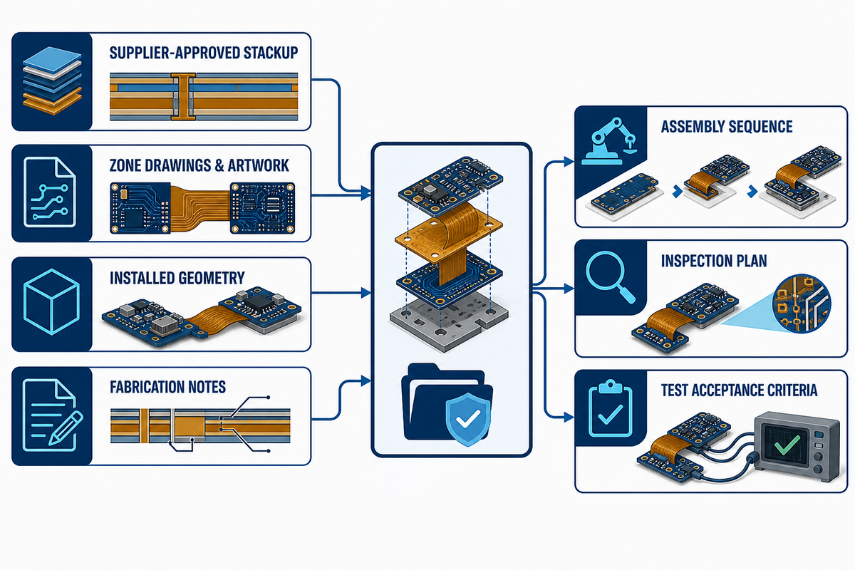
A release-ready rigid-flex package connects the supplier-approved stackup, zone drawings, artwork, installed geometry, fabrication notes, assembly sequence, inspection plan, and test acceptance criteria. Cost and lead-time discussions should use that same controlled package. Otherwise, quotations describe different products and late engineering changes appear as unexplained supplier variation.
Invite the fabricator into the review before routing density makes changes expensive. Ask for written disposition of the construction, transitions, bend region, coverlay openings, stiffeners, panel handling, coupons, controlled impedance, and acceptance evidence. Then bring the assembler into the same conversation: folding, support tooling, component clearance, test access, and final inspection can change the release.
Board price is one line of a system comparison. Include connectors, cables, assembly touches, fixtures, inspection, test access, yield loss, field replacement, and revision cost. Mark each estimate’s owner and quotation date instead of presenting it as universal rigid-flex pricing.
The Rigid-Flex Release Package Checklist
| Requirement | Recommended range | Confirm in RFQ |
|---|---|---|
| Installed shape and bend direction | Project-defined CAD and drawing | Supplier review complete |
| Flex duty statement | Installation, service, or dynamic | Motion profile attached |
| Stackup and material set | Supplier-approved construction | Substitution controls stated |
| Transition geometry | Construction-specific | Section view approved |
| Controlled electrical features | Net- and region-specific | Model and coupon agreed |
| Panel and work-in-process handling | Supplier and assembler defined | Packaging method included |
| Assembly tooling | Process-specific fixture plan | Fold and support sequence reviewed |
| Inspection and acceptance | Contract-defined criteria | Records and sampling agreed |
| Qualification and functional test | Risk- and program-defined | Pass/fail limits approved |
IPC’s public product page says IPC-6013E covers qualification and performance requirements for flexible boards designed to IPC-2221 and IPC-2223, including rigid-flex multilayers and rigid-to-flex transition topics. Use that relationship to organize document control, but confirm the revision and acceptance criteria invoked by your purchase contract. Standards ownership is not the same as product certification.
PCBark describes its service path as design-for-manufacturing review, component sourcing, fabrication, assembly, and functional testing. That first-party workflow is relevant when a buyer wants one accountable handoff; discuss the actual deliverables and evidence for the specific order. Review its rigid-flex PCB manufacturing scope and turnkey PCB assembly services before issuing the package.
Key takeaway: Quote and build from one controlled release package so design intent survives every handoff.
What’s Changing: Standards and Miniaturization Move Risk Into the Interfaces
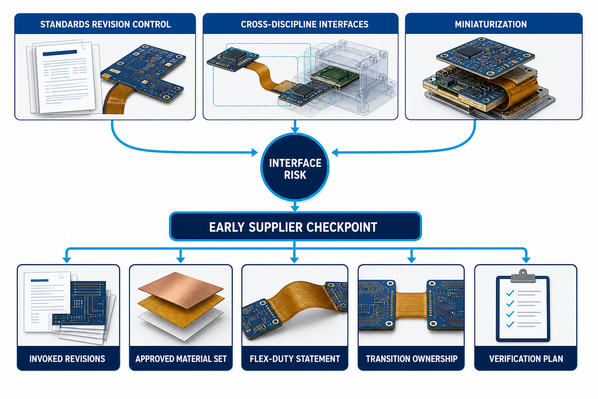
Rigid-flex teams planning new releases in 2026 should treat standards revision control and cross-discipline interfaces as active design work. Miniaturization pushes transitions closer to components, restraints, thermal hardware, and high-speed paths, while newer standards make copied notes easier to misapply. Early supplier review now carries more value than a late artwork-only check.
The official IPC store lists IPC-2223 Revision F as the current English revision, released on May 27, 2026. That date is a concrete document-control event, not proof that every contract automatically changed. Check the revision named by the customer, quality plan, drawing notes, and supplier quotation; resolve differences before data freeze. The official page also says IPC-2223 works with the base IPC-2221 standard, so revision control cannot be handled as a single isolated line.
Measured search history for “rigid flex PCB design” rose in the recent comparison used here, but demand is background, not an engineering requirement. Searches combine stackup, material, bend-radius, example, and calculator intent. Universal calculator values remain unsafe while construction and duty are unknown.
For projects entering concept work in the second half of 2026, schedule a standards-and-supplier checkpoint before the first dense layout review. Record the invoked revisions, approved material set, flex-duty statement, transition ownership, and verification plan. That small control prevents the most damaging kind of late change: one that crosses mechanical, fabrication, assembly, and quality files at once.
Key takeaway: Current-document control and interface ownership are design inputs, not administrative work after layout.
Frequently Asked Questions About Rigid-Flex PCB Design
Rigid-flex questions often sound numerical, but useful answers begin with architecture, construction, and duty. IPC-2223’s public scope helps identify the design document, while the answers below separate general design logic from values that require a supplier-approved stackup or program contract. That boundary helps engineering teams ask better questions without turning one manufacturer’s process guidance into an industry-wide rule.
What is rigid-flex PCB design?
Answer
Rigid-flex PCB design combines rigid circuit boards and an integral flex circuit in one controlled construction. Components are generally placed on rigid areas, while flex sections carry conductors between them or permit installation and motion. The work includes mechanical geometry, materials, stackup, routing, transitions, fabrication, assembly, and verification. It is therefore an electromechanical architecture task, not merely a different PCB outline.
When should engineers choose a rigid-flex PCB instead of separate rigid boards connected with cables?
Answer
Choose rigid-flex when connector removal, repeatable installation, folded packaging, lower interconnect count, or controlled motion produces a clear assembly-level benefit. Keep separate boards and cables when independent replacement, rapid architecture change, simple field repair, or uncontrolled movement matters more. Compare installed cost and risk, including connectors, labor, inspection, test, and service, not only the quoted bare-board price.
What materials are used in a rigid-flex PCB?
Answer
Rigid-flex constructions may combine flexible insulating films, metallic conductors, rigid-board dielectrics, coverlay, bonding materials, stiffeners, finishes, and optional shielding. Polyimide is a common flex dielectric family, but the name alone does not define performance. Copper type, thickness, adhesive system, layer count, lamination sequence, openings, and transition details must be selected and approved as a construction by the intended fabricator.
What is the minimum bend radius for a rigid-flex PCB?
Answer
There is no universal minimum. Total thickness, layer count, copper, coverlay, bend direction, angle, forming method, and static or dynamic duty all matter. Request a fabricator-approved bend rule for the exact stackup and validate the installed condition.
Why are rigid-flex PCBs more expensive than standard rigid PCBs?
Answer
Rigid-flex boards combine materials and process steps that require construction-specific planning, tighter handling, additional inspection, and supplier expertise. The bare board can cost more than a rigid board, yet the system may remove connectors, cables, assembly operations, and routing fixtures. A fair comparison includes fabrication yield, assembly labor, test access, field replacement, and change cost. Prices depend on the actual build and supplier quotation, so generic price-per-area figures are not reliable planning evidence.
Can components or vias be placed near the flex-to-rigid transition?
Answer
Placement near a transition depends on construction, strain path, assembly loading, and the fabricator’s rules. Do not apply a universal keepout. Mark the proposed geometry, installed bend, and nearby features, then obtain written supplier approval before routing is frozen.
Are rigid-flex PCBs more reliable than cable-connected assemblies?
Answer
A rigid-flex circuit can remove mating interfaces and reduce wiring variation, but reliability is conditional. Construction, motion, process control, installation, inspection, and verification decide the result. A well-controlled cable assembly can outperform a poorly defined rigid-flex design.
About PCBark
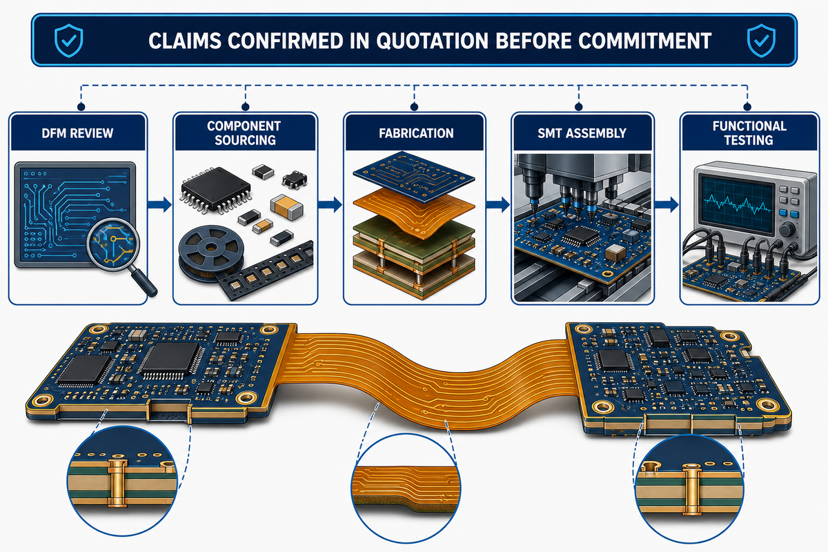
According to PCBark, the firm has 16+ years of experience and offers annual production capacity of 500,000 m². Its service flow covers design-for-manufacturing review, component sourcing, fabrication, SMT assembly, and functional testing. The company’s first-party claims should be confirmed in an individual quotation, and any standards language should be tied to the contract-invoked document rather than inferred from an IPC public scope page.
How this guide was prepared
The evidence base for this guide combines public IPC document descriptions, NASA quality and application material, an open-access flexible-circuit reliability study, measured search evidence, and PCBark-supplied company information. Public standard pages support scope and revision facts only; licensed requirements and project contracts remain controlling. No universal bend, via, test, certification, or aerospace-qualification value was inferred.
Prepare a manufacturable rigid-flex release
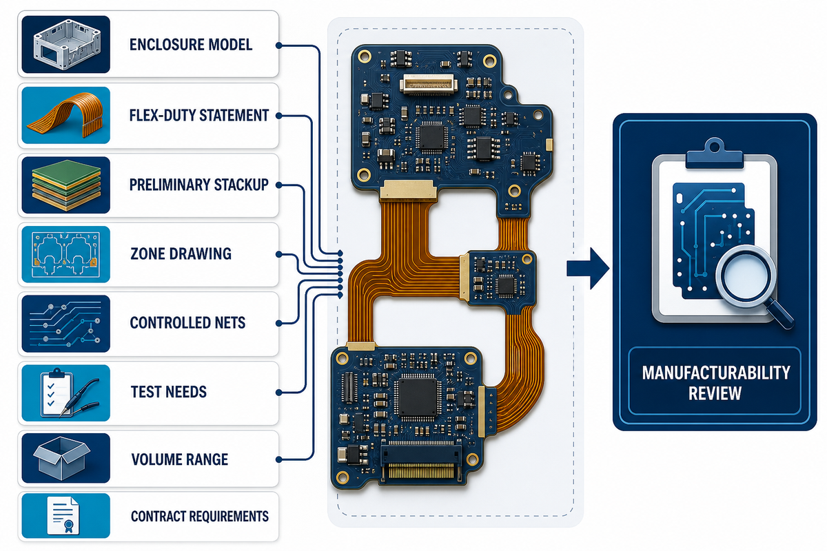
Send PCBark the enclosure model, flex-duty statement, preliminary stackup, zone drawing, controlled nets, test needs, volume range, and applicable contract requirements. Use the relevant IPC public page only to identify a document; your contract controls the revision and acceptance criteria. PCBark can review the package from fabrication through assembly and functional test.
Related Articles and Services
- Multilayer flex PCB design and construction guide
- Aerospace PCB design guide
- Turnkey PCB assembly guide
References & Sources
- IPC. IPC-2223 Standard Only: current revision and public scope. Accessed August 2026.
- IPC. IPC-6013E: Qualification and Performance Specification for Flexible/Rigid-Flexible Printed Boards. Public product details.
- NASA Office of Safety and Mission Assurance. Quality. Risk-based, mission-tailored quality guidance.
- NASA Technical Reports Server. Rigid-flex electronics application for shape-changing robotic systems.
- Kiernich, A., Kalenik, J., Stęplewski, W., Kościelski, M., and Chołaj, A. “Impact of Particular Stages of the Manufacturing Process on the Reliability of Flexible Printed Circuits.” Sensors 25(1), 140 (2025). DOI: 10.3390/s25010140. PubMed PMID: 39796932; also indexed by the Directory of Open Access Journals.
- IPC Education. PCB Design for Rigid-Flex Boards. Training scope page.







![16-24 Layer PCB: Stackup, Lamination & Design Guide [2026]](https://pcbark.com/wp-content/uploads/2026/07/16-24-layer-pcb-guide-featured-2-150x150.png)


