Get in touch with PCBark Company


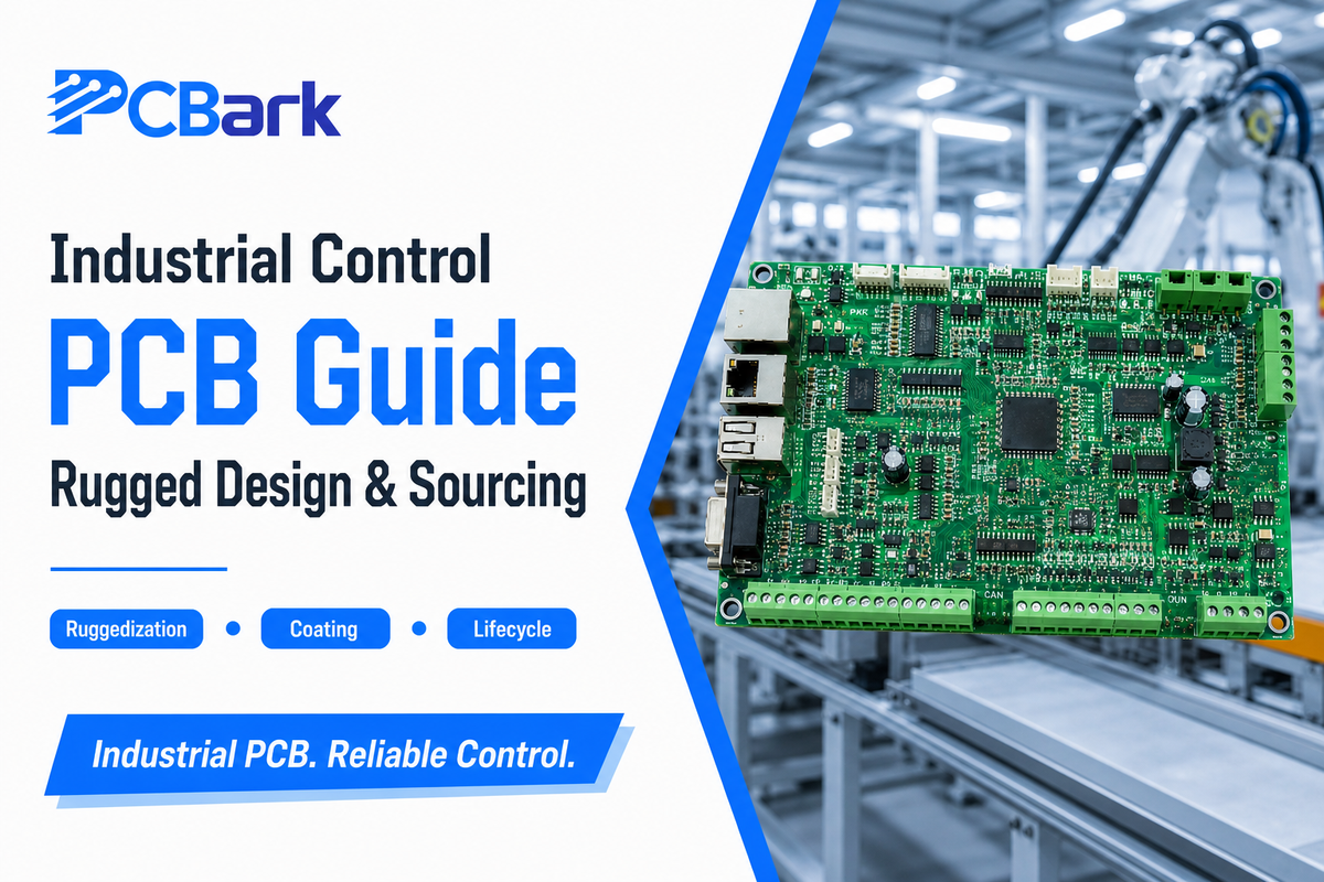
An Industrial Control PCB Field Guide. Ruggedization, Temperature Grades, Coating, Standards, and Sourcing. Updated: July 2026 Reviewed by the Shenzhen Linghangda Technology Co., Ltd. (PCBark) technical team.
Industrial Control PCB — At a Glance
| Typical layer count | 4–12 layers |
| Copper weight | 2–6 oz (heavy copper to ~20 oz) |
| Industrial temperature grade | −40 °C to +85 °C (grade-dependent) |
| Substrate | High-Tg FR-4 · polyimide · metal-core |
| Coating | Conformal coat per IPC-CC-830 |
| Workmanship | IPC-A-610 Class 3 |
| Design service life | 10–15+ years |
Machinery that runs a factory floor rarely fails because of the software. It fails because a circuit board inside a drive, a sensor node, or a programmable logic controller stopped surviving its environment.
An industrial control PCB is the printed circuit board built to prevent exactly that-and the design choices that separate it from a consumer board are more specific, and more counterintuitive, than most vendor pages admit.
This guide walks through what actually makes a board industrial-grade, how five environmental stressors map to concrete countermeasures, how to pick a temperature grade without overpaying, and how to score a design’s ten-year lifecycle risk before you commit.
Every technical claim here’s tied to a primary source-a standard, a government reliability document, a peer-reviewed study, or a granted patent.
Industrial control PCBs are printed circuit boards engineered to run machinery and processes reliably in demanding factory environments.
They prioritize environmental resilience, power handling, and long service life over the size and cost priorities of consumer electronics. What defines them is not a single label but a stack of decisions: temperature grade, conformal coating, derating margin, and component-lifecycle planning.
Key takeaways
- IPC Class 3 is the floor, not the definition. Reliability comes from derating, thermal path, coating, and lifecycle planning-the Class-3 label alone doesn’t make a board industrial.
- More layers and heavier copper don’t equal more reliable. Heavy copper solves current and heat; reliability is a solder-fatigue and derating question.
- Not every industrial board needs −40 °C to +85 °C. Grade choice depends on enclosure ambient plus self-heating; over-speccing wastes cost.
- Over ten years, component obsolescence costs more than the bare board. A cheap board can become the most expensive program.
What Is an Industrial Control PCB?
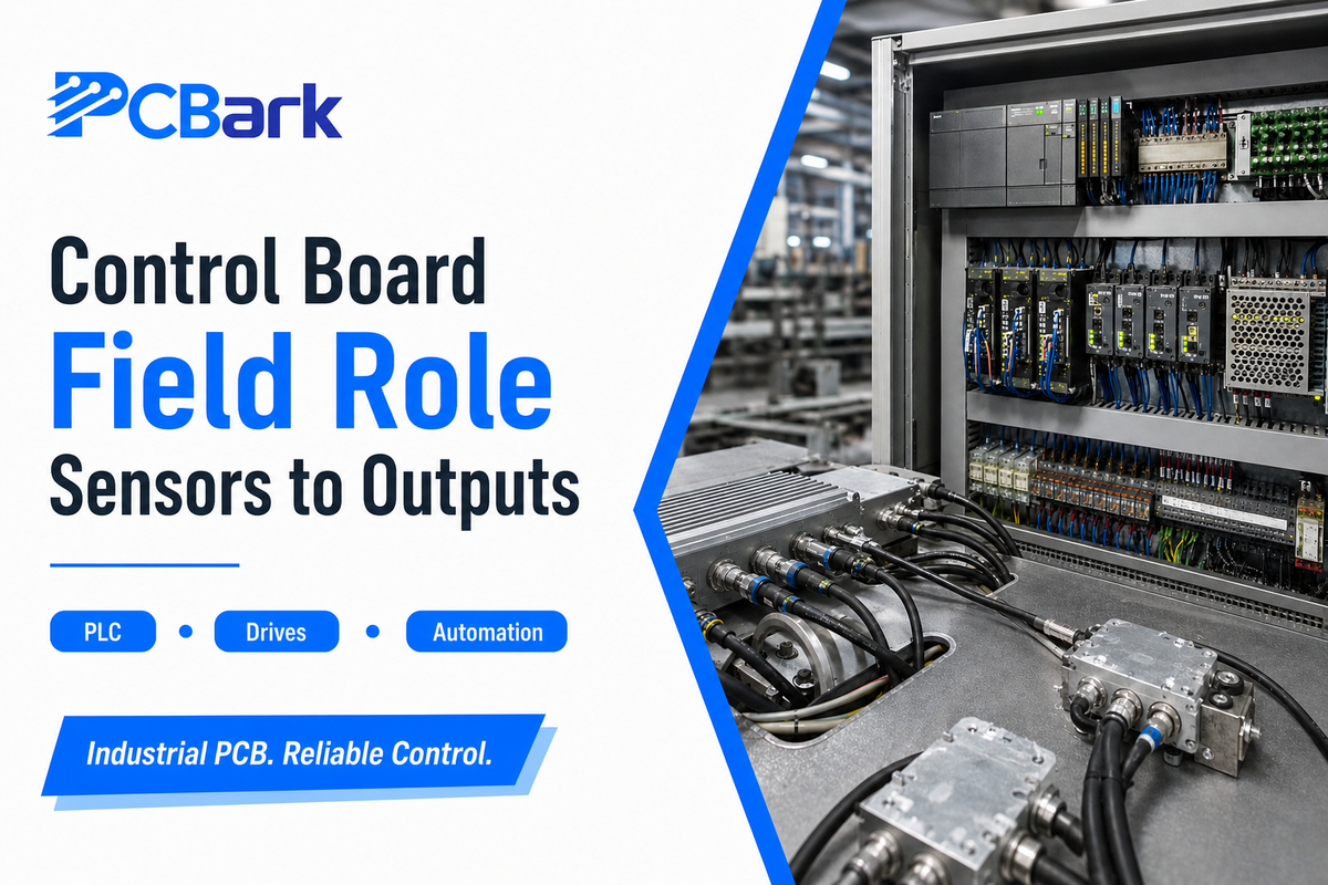
An industrial control PCB is the circuit board at the core of equipment that senses, decides, and drives-reliably, for years, in conditions that would shorten the life of an ordinary board. It sits inside programmable logic controllers (PLCs) at the heart of factory automation, motor drives and inverters, process-control instruments that watch temperature, pressure, and flow, motion controllers, and the growing population of industrial IoT nodes. These control systems share one demand: keep working when the environment turn hostile.
That distinction from a consumer board is functional, not cosmetic. NASA’s engineering literature on moving commercial parts into harsh environments frames the problem plainly: reliability in the field is set by parts selection, derating, and environmental screening, not by the schematic alone (NASA NEPP EEE-INST-002).
A phone board optimizes for thinness and unit cost across a two-year life. An industrial control board optimizes for continuous operation and predictable failure behavior across ten to fifteen. That single change in priority cascades into every material and process choice that follows.
Quick note on a naming gotcha: “control PCB” sometimes gets confused with “process control block,” a computer-operating-system construct. Here it means the physical circuit board – the hardware enabling any machine. If that hardware is something you manufacture, see how PCBark approaches industrial PCB manufacturing for control-grade equipment.
What Actually Makes a Board “Industrial-Grade”?
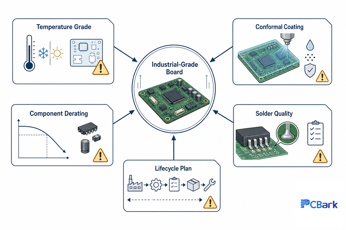
An industrial control PCB is industrial-grade when its temperature range, coating, component derating, solder quality, and sourcing plan are designed for industrial control systems, not just consumer hardware. Industrial automation, industrial automation and control networks, and other industrial control applications depend on boards that tolerate vibration, humidity, high temperatures, power supplies, and service life.
First, here’s a non-obvious truth, but critically important as most manufacturer web pages misstate it: IPC Class 3 is a floor for cleanliness (solder joints, plating), not a definition of “industrial.” Class 3 tells a fab house what a “clean” board must look like. It doesn’t state what operating ambient temperature the design must survive, if condensation is likely to form, or whether one of the components will be discontinued by the supplier by the time the product reaches year four of field deployment.
Four parameters are at play and must be satisfied for any board to be considered industrial:
- Use the board’s actual operating range to set temperature grade, and derate.
- Select conformal coating matching environmental contaminants and humidity.
- Include enough derating so that stress is always below component datasheet limit.
- Plan the bill of materials such that component lifecycle extends beyond product lifetime.
Among these parameters, derating leads to more avoidable field failures than anything else. As widely-cited design guidance puts it, datasheets give you maximum ratings, not the safe operating points, treat any maximum as a target and you invite failure.
NASA’s formal method for worst-case analysis captures this same idea in its structure of comparing the stress applied to each part against the rated capability (NASA Worst-Case Circuit Analysis). Not every functional circuit board is a reliable board; when deciding whether to design to Class 3, consider consulting an IPC class decision helper tool.
Takeaway: If a supplier’s only answer to “is this industrial-grade?” is “it’s Class 3,” keep asking. That label is necessary, not sufficient.
The 5 Environmental Stressors: A Ruggedization Grid
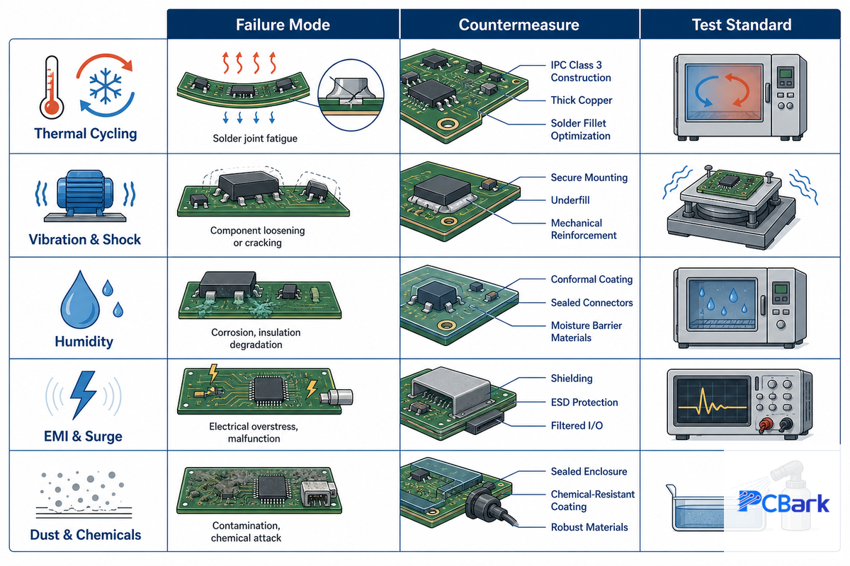
Boards in the field will fail because of one of five stressors, each with a specific antidote and test standard. We refer to these as the 5-Stressor Ruggedization Grid, a means to translate “design a rugged board” into a checkable design specification. Thermal cycling is the most widely studied stressor: one finite-element simulation of a Sn3.5Ag solder joint cycled from −55 °C to +125 °C showed cracks initiating where alternating shear strain concentrates at the joint interface (peer-reviewed study, PMC). Treat it as mechanism evidence, not a universal field-life promise.
This mechanism is exactly what we need to mitigate with ruggedization design practices.
5-Stressor Ruggedization Grid
Each row represents a stressor on a board in the field, paired with the countermeasure against that stressor and the testing that validates the fix – in essence, an embedded design checklist for use in design reviews.
| Stressor | Failure mechanism | Design countermeasure | Governing standard |
|---|---|---|---|
| Thermal cycling | Solder-joint fatigue, delamination | High-Tg laminate, thermal relief, matched CTE | IEC 60068-2-14 |
| Vibration & shock | Lead cracking, connector fretting | Staking, underfill, mechanical mounting | IEC 60068-2-6 / -2-27 |
| Humidity & condensation | Corrosion, dendrite growth, leakage | Conformal coating, trace clearance | IPC-CC-830 |
| EMI, EFT & surge | Logic upset, latch-up, damage | Ground planes, TVS/filtering, isolation | IEC 61000-4 |
| Dust & chemical | Contamination bridging, attack | Coating + IP-rated enclosure | IEC 60529 (IP) |
Notice how the grid reveals the inadequacy of single fixes. Coating handles dust and moisture but won’t fix a problem from vibration; a beefy ground plane will manage EMI issues but not the stresses of temperature cycling.
Ruggedization involves every item in the row, not one miraculous solution. In particular for the EMI row, achieving this goal requires designing for proper return paths and controlled-impedance RF PCB techniques, not just adding passive components.
Temperature Grades & Substrate Materials: The −40 °C / +85 °C Grade Gate
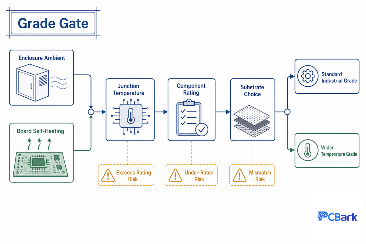
Two suppliers will give you two different answers to a question about the operating temperature for an industrial board: one may specify −40 °C to +125 °C and the other −40 °C to +85 °C. That conflict is the point. Grade choice is set by the enclosure’s ambient temperature plus the board’s own self-heating, not by a catalog superlative.
Worked example — sizing the grade
A control board sits in a cabinet that reaches 55 °C ambient. At full load, its regulators and drivers add roughly 20 °C of local rise, so junctions reach about 55 + 20 = 75 °C. Components and substrate must be comfortable to at least 85 °C.
A standard industrial-grade part or substrate, instead of a −40 °C / +125 °C automotive-grade component, saves money without hurting field life in this cabinet. Move that board outdoors in a −30 °C climate, and now the cold-end limit of the component, not the hot end, dictates the selection.
It’s no different with substrate. Basic FR-4 (Tg near 130–140 °C) suffices for a benign appliance, while high-Tg FR-4 (Tg ≈ 170 °C) gives headroom for a hot or high-power design, and polyimide is for continued elevated-temperature use. Metal-core substrate dissipates heat from concentrated power-stage designs.
These grades are described by the IPC-4101 laminate specification. Selecting a substrate laminate involves stack-up decisions as much as material selection; a material stack-up selector should match laminate to the operating window. If you’re curious about how to derate temperatures on real devices in use, NASA’s parts-selection guidance is as authoritative a public source as there is (NASA NEPP).
Layer Stackup, Heavy Copper & Thermal Management
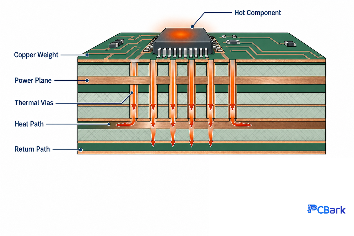
Retiring myth number 2: it isn’t inherently more reliable just because a board has more layers and uses heavier copper. Heavy copper addresses an amps-and-heat issue; it allows a trace to support higher current and distribute more heat. Reliability addresses thermal paths and the stress of solder joints over time.
It’s just as possible to create a fragile 12-layer board as a solid 4-layer board.
Worked example — copper weight vs trace width
For example, if a motor-drive trace needs to carry 10 A on an outer layer with no more than a 10 °C rise, IPC-2152’s current-capacity charts put that near a 200-mil trace width in standard 1-oz copper. Move to 3-oz heavy copper and the same current can fit in about 60–70 mil. Copper weight is primarily a packaging and thermal lever, not a reliability feature in itself.
In an OEM motor-drive application, the wrong copper choice becomes a field risk because heat is a root cause, not just a routing problem. PCBark’s in-house DFM review treats the 10 °C rise limit, 1-oz versus 3-oz copper, and 8–12 layer stack-up as one thermal path; the resolution is built around IPC-2152 sizing, USPTO heat-spreader records, and the process controls behind ISO 9001 / IATF 16949 production. That is the trade-off to confirm against real current, enclosure airflow, and inspection limits before the board moves into volume.
Where reliability really gains is heat path: copper pours, thermal vias, and metal-core or insulated-metal substrates that take heat away from junctions. The patents have caught onto this line of reasoning: conformal metallic coating applied as a heat spreader and EMI shield (US 6,965,071 B2), and conformal thermal interface materials as the path between a hot component and its sink (US 6,054,198 A). For current designs, run your trace widths through a PCB trace current-capacity calculator before choosing an 8–12 layer multilayer PCB stack-up.
Conformal Coating & Board Protection
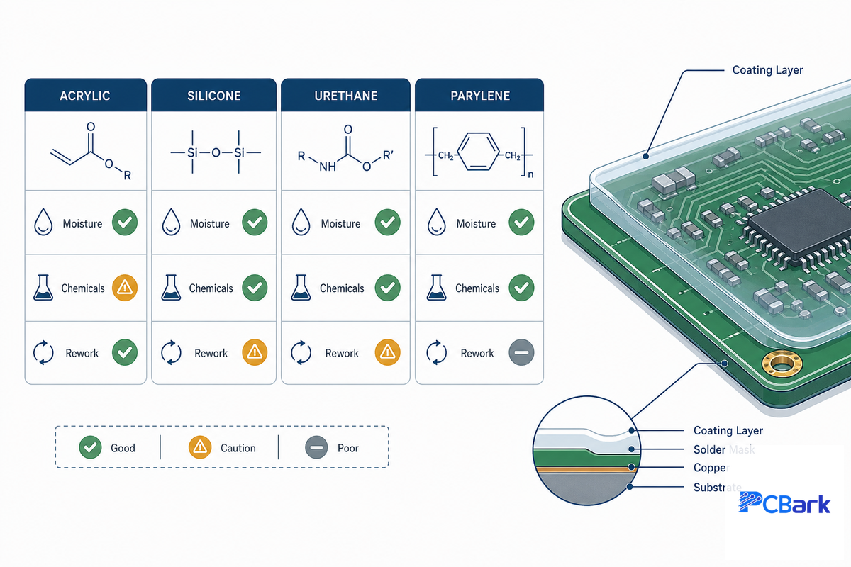
Conformal Coating is by far the cheapest way to add a bit of reliability to a board exposed to humidity, dust, or chemicals. This becomes necessary-field engineers say-to prevent condensation and dendritic growth when ambient temperatures shift. But not all coatings are created equal; the four common chemistries differ wildly in terms of temperature range, chemical resistance, reworkability, and cost. Treat the ranges below as screening ranges only; supplier datasheets and the exact formulation override the table.
| Coating | Temp range | Moisture / chemical | Reworkability | Relative cost |
|---|---|---|---|---|
| Acrylic (AR) | ≈ −60 to +125 °C | Good moisture, poor solvent | Easy | Low |
| Silicone (SR) | −55 to +200 °C (specialty higher) | Good moisture, flexible | Moderate | Medium |
| Urethane (UR) | ≈ −65 to +130 °C | Excellent chemical/abrasion | Hard | Medium |
| Parylene (XY) | ≈ −165 to +200 °C | Excellent barrier, conformal | Very hard (plasma) | High |
Two facts omitted by most vendor Web pages: First, coating choice is bidirectional. Parylene can fit very low-temperature screening ranges, while silicone is often selected for high heat, so don’t just choose parylene because it is “always the best.” Match the coating to the application’s actual extremes, then verify against the supplier datasheet; public academic property data on these chemistries backs up the comparison (Rutgers, parylene properties). Second, properly applied coating is very thin, on the order of tens of microns, and has virtually no impact on thermal performance unless the thermal path depends on heat passing through the coating.
A third nonmaterial factor can move the reliability needle: pre-coating cleanliness, uniform film thickness and a plan for reworking it. Coat anything less than clean and you’ll fail the part, regardless of the material you chose. These parameters are qualified per IPC-CC-830.
Standards & Compliance for Industrial Control Boards
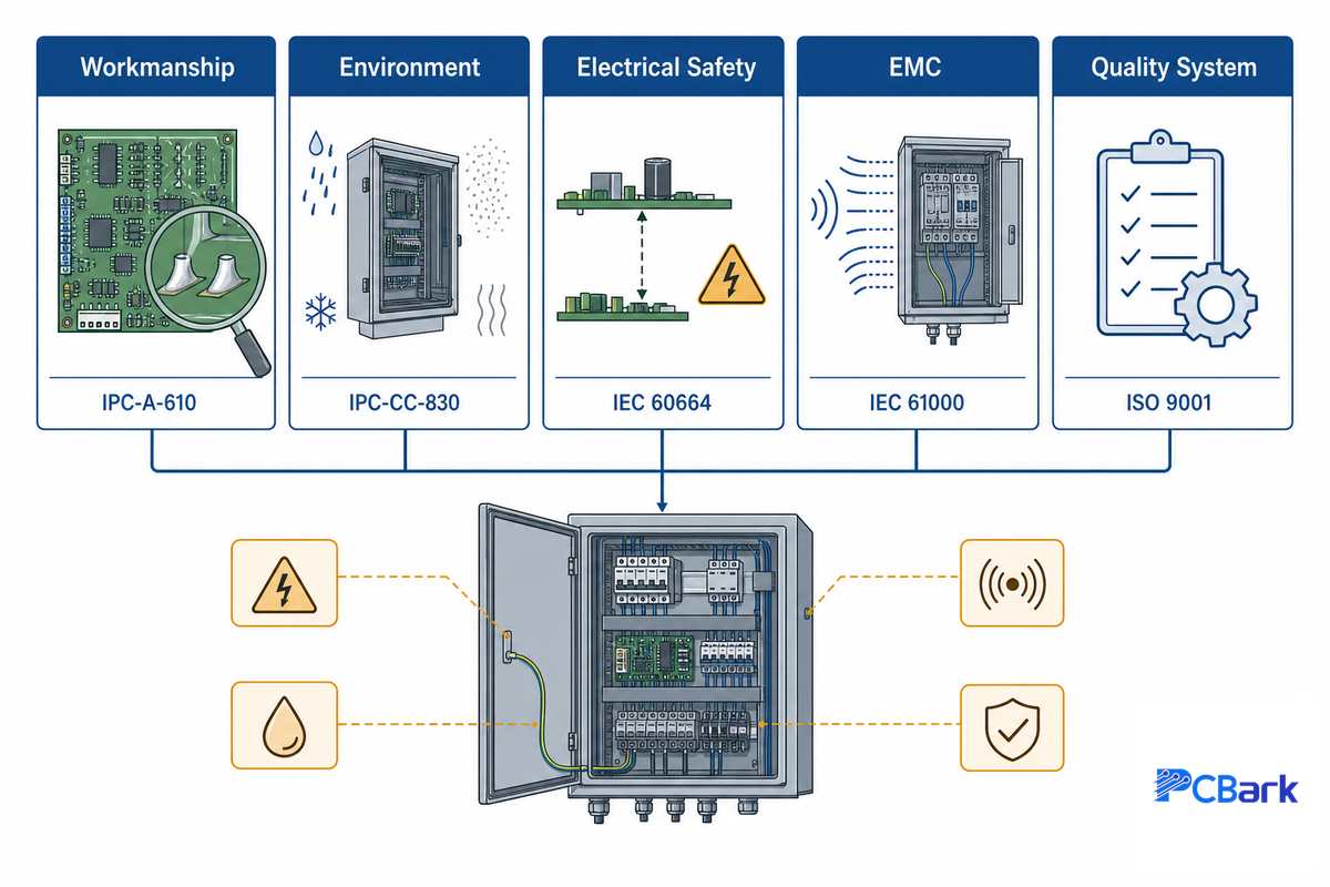
Which standards apply to a PCB in an industrial controller? This is not nearly as many as you think; a printed spec with the letter revision avoids expensive misunderstandings on a quote. Use the table below for the relevant subset and the applicable revision where it matters.
| Standard | Category | What it governs |
|---|---|---|
| IPC-A-610J (2024) | Workmanship | Acceptability of electronic assemblies (Class 3 = high-reliability) |
| IPC-6012F | Qualification | Rigid printed-board performance qualification |
| IPC-CC-830C | Coating | Conformal-coating qualification and conformance |
| UL 94 | Flammability | Laminate flame rating (e.g. V-0) |
| UL 796 | Process | Printed-wiring-board process safety |
| IEC 60664 | Electrical safety | Creepage and clearance for working voltage / pollution degree |
| IEC 61000 / CISPR | EMC | Immunity and emission limits |
| IEC 61508 | Functional safety | SIL levels for safety-critical control loops |
| ISO 9001 | Quality system | Quality-management-system certification |
| IATF 16949 | Quality system | Automotive-adjacent quality management |
| RoHS | Materials | Restriction of hazardous substances |
| REACH | Materials | Chemical registration and restriction |
An honest boundary: PCBark builds to IPC-A-610 Class 3, ISO 9001, and IATF 16949. We do not hold or imply ITAR registration, AS9100, or ISO 13485. If your program needs those, ask any supplier to show the certificate, not the claim.
Design & Sourcing: DFM, Testing & Choosing a Manufacturer
Design in and test reliability in these two lists.
For industrial control PCB assembly, separate the job into PCB fabrication, electronic manufacturing, component sourcing, and quality control before choosing a PCBA manufacturer. Strong control PCBA suppliers document design for manufacturability, wave soldering limits, reflow profiles, and engineering support instead of offering only broad manufacturing services.
For industrial control projects, specify industrial systems, industrial products, and industrial applications separately. A professional industrial PCBA partner can adapt flexible PCB, high-performance PCB, and specialized PCB designs for large-scale industrial equipment, but only when industry standards, performance and reliability, and performance and durability are named in the acceptance plan. That is the difference between generic PCB solutions and high-quality PCB solutions built for high-quality industrial controls.
DFM items to lock in before fabricating the board: controlled impedance requirement, voltage related minimum clearance and annular ring, power plane thermal reliefs, stress from depaneling and panelization, and BOMs with identified second sources. NASA’s workmanship standard is a useful public benchmark for how tightly these process controls can be specified (NASA-STD-8739.10).
| Test method | Catches | Coverage |
|---|---|---|
| AOI (optical) | Placement, solder shape | 100% visible joints |
| X-ray | BGA/QFN hidden joints, voids | Hidden interconnects |
| ICT / flying probe | Opens, shorts, wrong values | Electrical net integrity |
| Functional test | Real-world behavior | Board as a system |
PCBark’s stated capability covers in-house SMT assembly with AOI, X-ray, ICT and flying-probe inspection and testing, plus quote-stage DFM review. A reputable shop proves capability on a first-article prototype before full-volume runs, so failures surface once instead of thousands of times. When considering potential control-board suppliers, inquire how many of your joints each method actually inspect, and demand functional test against criteria you define.
The 10-Year Cost Picture: Obsolescence & Lifecycle
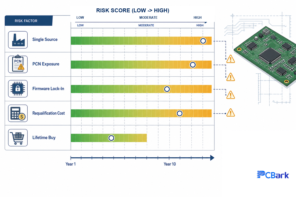
Third and most costly myth is that bare board price isn’t the driver for a ten year program. Many industrial equipment are designed for 10-15+ years lifespan. Over this lifecycle, component obsolescence, re-qualification and single source risk far outweigh initial PCB cost of ownership and the initial fabrication quote.
Both NASA’s parts-reliability effort and the governments own guidance documents treat life cycle and sourcing risk as high-priority engineering concerns (NIST SP 800-53 Rev 5, Supply Chain Risk Management).
10-Year Obsolescence Scorecard
Design scorecards are a quick method to assess design risk.
Rate each item 0(low)-2(high) and then multiply by its weighting to reach a total score.
| Risk factor | Weight | What raises the score |
|---|---|---|
| Single-source parts | ×3 | No qualified second source |
| Component lifecycle stage | ×3 | Parts already flagged near end-of-life |
| Package technology | ×2 | Exotic packages with short roadmaps |
| Change control | ×2 | No PCN/EOL monitoring in place |
| Lifetime-buy plan | ×2 | No last-time-buy or stocking strategy |
Scores below 6 should be considered low risk; 6-12 requires mitigation; and greater than 12 requires a redesign of the high-risk areas.
Common mitigation approaches include form-fit-function alternates; product change notice (PCN) monitoring; and lifetime buys for single-source parts. A dedicated PCB obsolescence risk calculator can make this scorecard a repeatable step in design review.
Where Industrial Control Electronics Are Heading (2026)
The next wave is less about fashion and more about denser industrial automation systems. In the field of industrial automation, Industry 4.0 projects place motion control, wireless modules, control units, and edge electronic components on the same board, so PCBs for industrial automation need stronger thermal planning, stable supply chains, and long-term reliability before release.
Far and away the most significant near-term development won’t be market growth, but where the computation take place. With an increasing number of industrial IoT and edge devices, more processing will take place directly on the control board itself, leading to greater complexity in layer count, thermal density, coating decisions, derating, and thermal pathways. Recent granted patents on conformal cooling for multi-die assemblies point the same way (US 12,288,733 B2).
Design a control board to be released in 2026-2027?
Ensure you include early design decisions for thermal margin and derating.
Another systemic change for networked control boards is the adoption of an OT security mindset that considers security and traceability requirements.
NIST’s OT security guidance now frames control boards as programmable devices interacting with the physical world, with their own threat surface (NIST SP 800-82 Rev 3). On the hardware front, this implies using security elements; only procuring parts from authorized channels; and full lot and date-code traceability – all elements of the sourcing discipline already favored by the obsolescence scorecard.
Market size matters only as background here; the design lesson is the driver, not the dollar figure. More connected equipment means more board-level compute, heat, traceability, and sourcing risk. For information on the vertical markets served by control boards, please see PCBark’s research on industrial IoT and robotics.
Frequently Asked Questions
What is a control PCB?
View Answer
A control PCB is the printed circuit board that gives a machine its “brain” — reading sensors, running control logic, and driving outputs such as motors, valves, or relays. In an industrial setting it is built for continuous operation and long service life. Note that “control PCB” sometimes gets confused with “process control block,” an operating-system term; in electronics it means the physical control board, not a software data structure.
What are the three types of PCB?
View Answer
Rigid, flexible, and rigid-flex are the three structural types. Rigid boards use a solid FR-4 or high-Tg laminate and suit most control cabinets. Flexible boards use polyimide film to fit tight or moving assemblies. Rigid-flex combines both, letting a single circuit fold into a compact enclosure while keeping rigid zones for connectors and heavy components — common in vibration-prone industrial equipment. Rigid-flex PCB options can be useful for tight control housings.
How do you ensure reliability for industrial environments?
View Answer
Reliability is layered, not bought with one feature. Start by deriving the temperature grade from enclosure ambient plus self-heating, then derate every component below its maximum rating. Add conformal coating matched to the humidity and chemical exposure, design a real thermal path with copper pours and thermal vias, and verify with automated optical inspection, X-ray, and functional testing. Finally, plan the component lifecycle so the board can still be built years later. Skipping any layer is where field failures start.
What temperature range do industrial control PCBs need?
View Answer
Commonly −40 °C to +85 °C, but the honest answer is “it depends on the enclosure.” Derive it from ambient plus self-heating rather than defaulting to the widest catalog grade.
What testing is done on an industrial control PCBA?
View Answer
Automated optical inspection (AOI) checks placement and solder shape on every visible joint; X-ray inspects hidden BGA and QFN joints for voids; in-circuit or flying-probe testing confirms electrical nets; and functional testing exercises the board as a working system against defined pass criteria. High-reliability programs add thermal-cycle and solderability checks, and many run a first-article prototype through the full suite before production.
Is IPC Class 3 required for industrial control boards?
View Answer
Class 3 is the common target for high-reliability industrial and control work, and many buyers require it — but it is a workmanship standard, not a guarantee of field reliability. A board can meet Class 3 and still fail from an under-rated part or missing coating. Treat Class 3 as the floor and pair it with derating, coating, and lifecycle planning.
Building an industrial control board?
Submit your next design for a free DFM review, or see PCBark’s industrial assembly services:IPC Class 3 compliant manufacturing with in-house AOI, X-ray, and ICT testing, plus turnkey design-to-functional-test services.
About this guide. These frameworks — the 5-Stressor Ruggedization Grid, the Temperature-Grade Gate, and the 10-Year Obsolescence Scorecard — are PCBark’s own synthesis of public standards and reliability literature, written to be used by any engineer regardless of who builds the board. Where we describe PCBark’s capabilities we state them as capabilities, not case studies. Technical claims are linked to their primary sources below, and every figure should be checked against your specific parts and environment.
References & Sources
- EEE-INST-002: Instructions for EEE Parts Selection, Screening, Qualification & DeratingNASA NEPP
- Worst-Case Circuit Analysis (WCCA)NASA S3VI
- NASA-STD-8739.10, Electrical Workmanship StandardNASA
- Failure Behavior and Mechanism of Solder Joint Under Thermal CyclingU.S. National Library of Medicine (PMC)
- Parylene Properties (comparative conformal-coating data)Rutgers University, Dept. of Physics
- SP 800-82 Rev. 3, Guide to Operational Technology (OT) SecurityNIST
- SP 800-53 Rev. 5, Security & Privacy Controls (Supply Chain Risk Management)NIST
- US 6,965,071 B2, Thermal-sprayed metallic conformal coatings as heat spreadersUSPTO / Google Patents
- US 6,054,198 A, Conformal thermal interface material for electronicsUSPTO / Google Patents
- US 12,288,733 B2, Conformal cooling assembly for multi-die electronicsUSPTO / Google Patents
- UL 796, Printed-Wiring Boards
- IEC 60664, Insulation coordination for equipment within low-voltage supply systems
- ISO 9001, Quality Management SystemsInternational Organization for Standardization
- Electric rail traction systems need specialized power managementEDN
Related Articles
- The complete PCB assembly guide
- Turnkey PCB assembly: what it includes
- Aerospace PCB design guide
- Medical PCB design guide
- Automotive control PCB capabilities