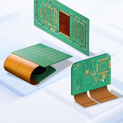
Flex PCB Assembly

Flex PCB Assembly & Rigid-Flex PCBA Services

Flex PCB assembly puts live components onto a circuit that has to bend, fold, and survive motion, and that’s exactly where a generalist line gets you in trouble. PCBark runs flex, rigid-flex, and FPC assembly as a controlled process, not a rigid-board afterthought: rolled-annealed copper, stiffener strategy, low-temperature reflow, and full functional test under one roof.

  • Flex · Rigid-Flex · FPC

    Build types assembled
  • 1–8 layer flex

    up to 20+ rigid-flex
  • RA ½–1 oz

    rolled-annealed copper
  • ENIG · OSP · Imm. Tin

    flex-rated finishes
  • AOI · X-ray · Flying Probe

    + functional test in-house
  • Sub-235 °C reflow

    low-temp polyimide profile
Request a Flex PCB Assembly Quote
Flex PCB Assembly
500,000 m²/yr turnkey EMS capacity
16+ yrs PCB & SMT manufacturing
IPC-6013 Class 1/2/3 flex qualification
One roof DFM → fab → assembly → test

Where Flex PCB Assembly Goes Wrong, and How PCBark De-Risks It

A flexible printed circuit (FPC) is a circuit etched onto thin polyimide film instead of rigid FR4, and flex PCB assembly is the step where components get printed, placed, and soldered onto that film, single-sided, double-sided, multilayer, or the flex section of a rigid-flex board.

The part most buyers underestimate is that assembly on a flexible circuit isn’t the same process you run on a rigid board, and treating it as if it were is where reliability quietly fails.

When failure does occur, it usually comes back as follows: The finished board passes a quick bench test, it gets installed in the product, and then we receive reports of traces cracking near the fold, solder joints shattering at creases, or the whole lot arriving improperly de-paneled. Failure analysis has thoroughly documented how cracks are formed: fatigue concentrates at traces where they connect to pads, not beneath the polyimide coverlay, and motion that bends from multiple angles is worse than single-axis movement. Because traces that are cracked will occasionally reconnect under pressure, parts appear to function properly for a while and then they don’t.

People who need this capability often search for flex pcb assembly, flexible printed circuit assembly, flex circuit assemblies, or flex PCB SMT assembly-it’s the same problem, regardless of terminology. PCBark plans for every one of these failures at the DFM stage, before paste ever touches the stencil. Below is the working checklist our flex line run against, informed by peer-reviewed flex-failure analysis: the defect, the root cause that produces it, and the countermeasure built into the process.

Flex Assembly Failure-Mode & Prevention Index

Assembly Failure Mode Root Cause PCBark Countermeasure
Trace cracking in bend zone Cyclic strain on brittle ED copper Rolled-annealed (RA) copper + traces routed out of the neutral bend axis + bend ratio ≥10:1
Solder-joint fracture near a fold Rigid joint inside a flexing region Stiffener under SMT/connector pads + teardrop pads at the trace-to-pad transition
Trace-to-pad crack / pad lift Stress concentration at the transition Extended coverlay over the transition + anchored annular rings
Tombstoning on flex Uneven heating on a flimsy substrate Rigid carrier fixturing + balanced pad design + slow thermal ramp
Coverlay delamination Trapped moisture / poor lamination Mandatory pre-bake + controlled-pressure lamination
Popcorn / blistering in reflow Absorbed moisture flashing to steam Pre-bake to drive off moisture before paste print
Cold / non-wetting solder Wrong profile for polyimide limits Sub-235 °C low-temperature reflow profile tuned to the stack
Bow and twist after reflow Asymmetric copper / stack-up Symmetrical stack-up design review at DFM
Component rotation / misplacement Flex movement during placement Machine-vision re-registration on the carrier
Reduced reliability after rework Extra thermal excursions grow intermetallics Capped rework cycles + AOI/X-ray verification

This is the difference between a vendor that “also does flex” and a line built for it. Every entry above maps to a process control you can ask any flex assembler to demonstrate, and most quick-turn brokers can’t.

Flex, Rigid-Flex & FPC Assembly, Build Types, Capabilities & Applications
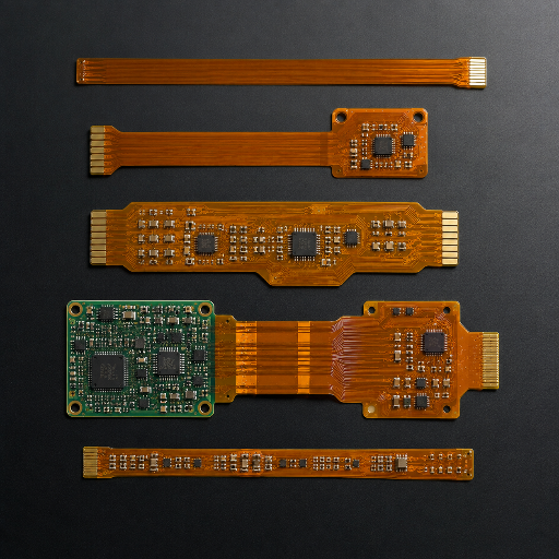
Choosing the wrong build type is the most expensive flex decision, and it happens before assembly. Push a dynamic design past about 0.4% bend strain and the traces crack in service; specify rigid-flex where a plain flex with a rigidizer would do and you add layers and cost for no reliability gain. The trade-off isn’t always obvious from a datasheet, which is why PCBark engineers the build type with you at DFM, because the right call depends on the neutral bend axis, layer count, and where the board actually flexes. This grid maps each build type our in-house flex line assembles with fine-line precision to its real bend behavior and the application it fit, unlike a generalist quote that treats every flex the same.

Flex, Rigid-Flex & FPC Assembly Build Types

Flex & Rigid-Flex Build-Type Decision Grid

Build type Layers Bend behavior Best fit (application)
Single-sided flex / FPC 1 Dynamic; ≥10:1 static, ~100× thickness dynamic FFC ribbon, printer carriages, motion sensors
Double-sided flex 2 Static ≥10:1; limited dynamic Wearables, cameras, hearing aids
Multilayer flex 3–8 Static ≥20:1 (medical-grade) Medical imaging/implants, high-density modules
Rigid-flex Rigid 4–20 + flex Install-bend / flex-to-fit Aerospace, defense, foldables, robotics
FPC SMT / chip-on-flex (COF) 1–2 Static LED strips, display interconnect, COF drivers

The bend ratios above are industry design guidance from flex circuit engineering practice: single- and double-sided flex tolerate a static bend radius of at least 10 times the circuit thickness, multilayer medical-wearable flex needs at least 20:1, and dynamic single-layer flex is generally held near 100 times thickness to keep strain under control. Static designs can run up to five layers; true dynamic flex is usually kept to a single RA-copper layer.

Engineering Note, Material & Stack-up

Standard flex copper weight is ½ oz rolled-annealed copper foil; 1 oz is reserved for high-current exceptions. Flex dielectric runs a tighter Dk than the woven glass used in rigid printed circuit boards, which helps controlled-impedance routing. Across flexible circuit and rigid-flex circuit PCB design we plate the vias and any plated through-holes for layer-to-layer connection, and choose between a polyimide (PI) coverlay and a liquid solder mask zone by zone. Surface finish is ENIG, immersion tin, or immersion silver by solderability and shelf life; PI film in an adhesiveless or acrylic-adhesive construction is selected for high-performance, high-density rigid-flex PCB builds. The same DFM discipline carries from bare-board PCB manufacturing through to finished PCB assemblies, and we review stack-up symmetry so the board doesn’t bow through reflow. For high-speed or antenna work we add an EMI shielding layer, shielding film or silver paste, a step common in flex circuit assembly for sensor and RF circuit boards; standard SMT soldering on flexible substrates is documented down to research-grade builds such as US Patent 12,108,539 (US Navy NRL).

Flex vs. Rigid PCB Assembly, and Full-Turnkey EMS vs. Quick-Turn Broker
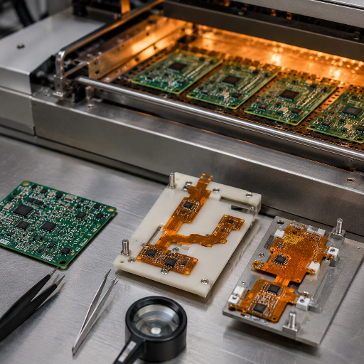
If you’ve only ever bought rigid FR4 assembly, the quote for flex will look high and the process will look unfamiliar. Both reactions are correct, and both have specific engineering reasons, the trade-off flex buy you is reliability in motion, not a lower bill of materials. Below is what actually changes on the line when the substrate can flex, step by step.

Flex-vs-Rigid Assembly Process Delta

Process step Rigid (FR4) Flex / Rigid-Flex
Moisture prep Often skipped Mandatory pre-bake
Handling Self-supporting Rigid carrier / panel fixturing
Copper type ED copper, ~1 oz RA copper, ½ oz typical
Reflow peak ~245–250 °C standard Sub-235 °C low-temp option
Joint reinforcement None Stiffeners + teardrop pads
Bend allowance N/A ≥10:1 static / ~100× dynamic
Laminate cost Baseline FR4 2–3× FR4 (industry estimate)
Dominant reliability risk Thermal-cycle fatigue Trace-to-pad bend fatigue

That last row is the one buyers miss. Reported flex trace-fatigue testing shows failure (defined as a 20% increase in resistance) at roughly 585 cycles in tension and 1,022 in compression, while extending polyimide coverlay over the stressed transition lifts cycle life from hundreds to thousands. Reliability on flex is bought at the design and process stage, not inspected in at the end.

Flex vs. Rigid PCB Assembly

Why “full-turnkey EMS” beats “quick-turn broker” on flex

The flex assembly market splits into two camps, and neither default is built for a serious flex program. On one side sit high-volume quick-turn brokers that quote flex cheaply but treat it like rigid FR4; on the other sit specialist shops that price flex at a premium and decline to stock the polyimide and adhesiveless materials your design may need. PCBark sits deliberately between them: a single facility that runs DFM, fabrication, component sourcing, assembly, and functional test in-house.

When fab and assembly answer to the same engineers, a coverlay or stiffener problem gets caught at DFM instead of surfacing as a field crack, and there’s no finger-pointing between a board house and a separate assembler. Because PCBark also handles flex PCB fabrication and works as a dedicated flex PCB manufacturer, the bare board and its assembly stay with one team, not an isolated service, the same discipline we bring to our wider PCB assembly services.

Reliability Engineering for Flex Assembly, Standards, Cycle Life & Defect Control

“Will it survive in the field?” is the question that should decide your flex assembler, and it has a documented answer set. Flex reliability comes down to three things: a clear stack of IPC standards, a measurable fatigue mechanism, and a short list of process controls that separate a flex build that lasts from one that cracks in the field in under 30 hours. PCBark builds and tests against all three.

The standards that actually apply

IPC-2223 describes the flex and rigid-flex sectional layout – thickness, radius, components’ placement;

IPC-6013 lays down the qualifications and performance criteria for the following flex Classes: consumer (Class 1), industrial and automotive(Class 2), high-reliability( aerospace, military and medical-meets the MIL-PRF-31032 specification-Class 3);

J-STD-001 governs the soldering process; IPC-A-610 establishes acceptable visual standards for the final assembly. we’ve built the flex assembly to your required Class and inspect the assembly to its matched specification.

This isn’t a country-of-origin question, contrary to the way the market portrays it. A specialist with vetted flex lines, RA copper, teardrop pad libraries, low-temperature reflow, and IPC-6013 control passes the reliability bar. A generalist that push flex through a rigid-board recipe doesn’t-regardless of factory location. Every flex assembly we provide comes with full inspection coverage: AOI, X-ray for concealed and BGA joints, flying probe test, and functional test.

Dynamic-Flex Cycle-Life Process Window

For those dynamic applications-where circuit bends continuously over its lifetime (e.g., printing platen, pivot hinge)- fatigue life is determined by strain, a well-understood principle. In general, strain below approximately 0.4% gives the circuit 1 million cycles, a strain of 0.8% approximately 50,000, and strains below 0.2% still more than a million cycles.

That’s why any dynamic flex construction is in the design held to one RA- copper layer, where traces lie in the neutral bendaxis; why the layout must result in strain figures below this maximum, and the assembly hasn’t formed an overly stiff joint within the bent circuit.

“On flex, the failures we chase are almost never in the open trace, they start at the trace-to-pad transition. Our standing rule is to extend the coverlay over that transition, add a teardrop, and keep the reflow profile under the polyimide’s limit. Get those three right and you move from hundreds of cycles to thousands.”
PCBark Engineering Team, Flex & Rigid-Flex Assembly

Quality, Certifications & In-House Test

Among buyer forums, the most frequent flex complaint has nothing to do with price, it’s QC that slipped. These issues are familiar: cold-solder joints shipped anyway, a header soldered against the data, panels that were never properly separated, and a slow drift in quality from a high-volume default supplier. The answer to “how do I avoid that” is verifiable inspection coverage, not a logo wall. Here’s what every PCBark flex assembly passes through before delivery:

IPC-6013

Flex qualification, Class 1/2/3

J-STD-001

Solder process control

IPC-A-610

Assembly acceptance

ISO 9001

Quality management system

AOI + AXI

Optical + X-ray inspection

Flying Probe

Bare + assembled e-test

Functional Test

In-house, to your test plan

Industry Certifications Click cards to select • Click front to enlarge

CE Certification
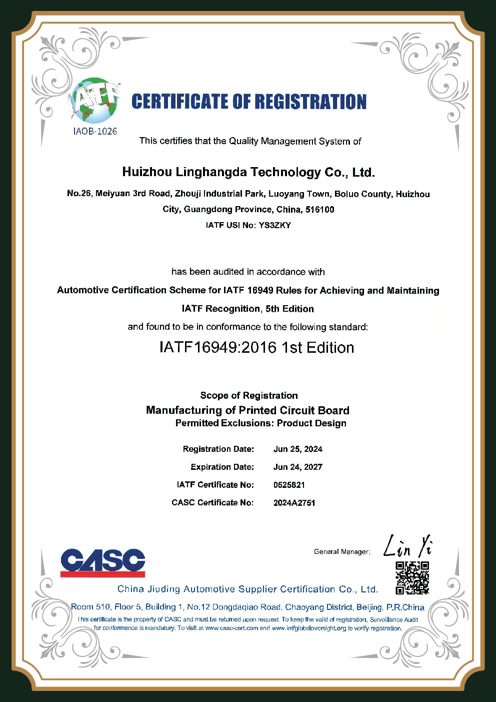
IATF16949 Certification
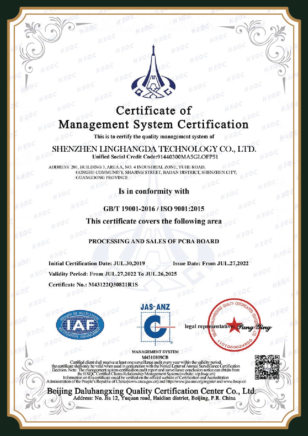
ISO 9001 Certification
ISO 14001 Certification
ISO 14001 Alternate
ISO 9001 Alternate
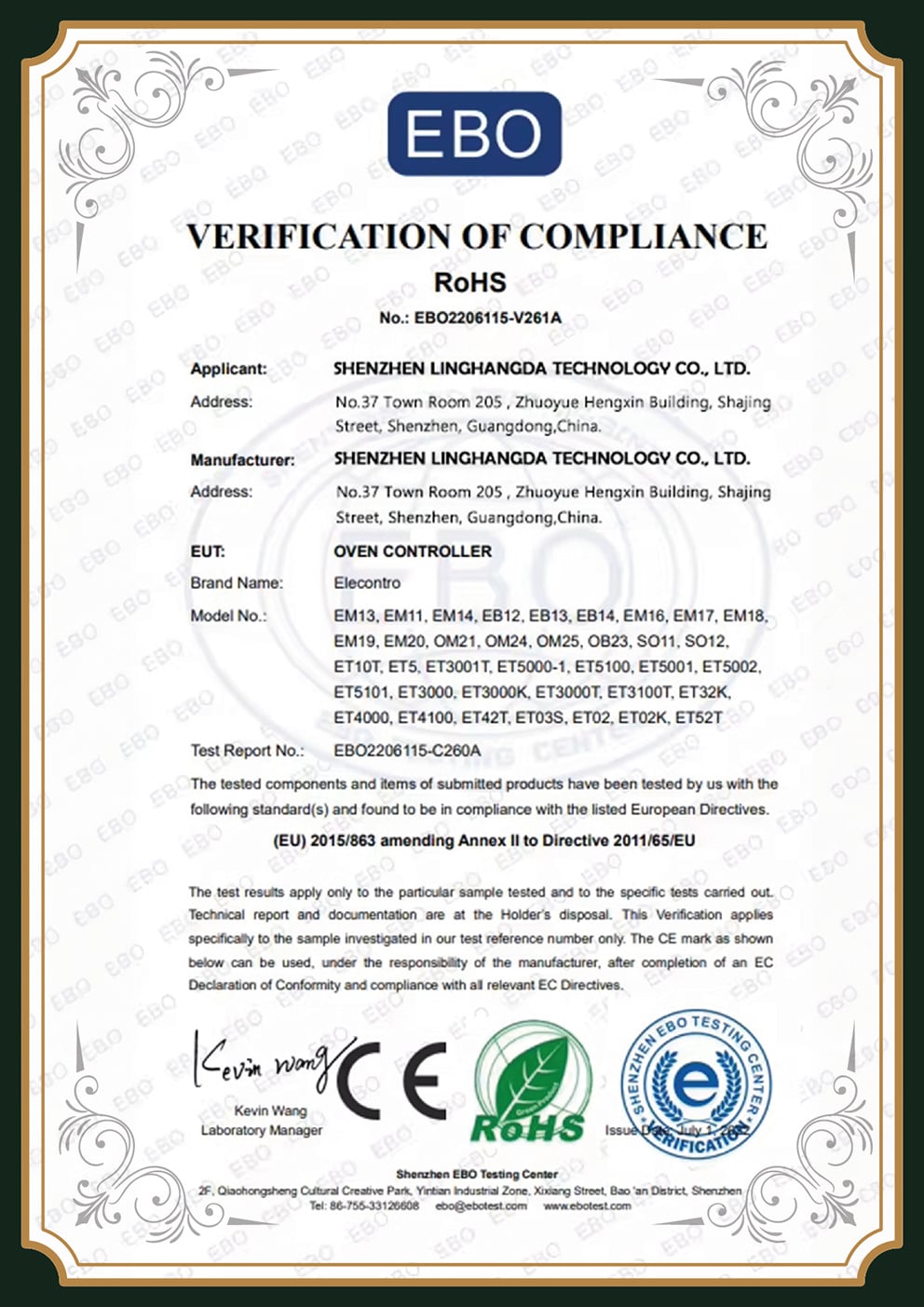
RoHS Compliance
UL Certification

Engineering Insight: X-ray Matters

X-ray matters specifically on flex because the joints most likely to fail, BGAs over a stiffener, joints at a fold, are the ones you can’t see with optical inspection alone. Running AOI, X-ray, and flying-probe in the same facility that fabricated and assembled the board means a defect is traced to its process step the same day, not shipped and disputed for weeks. Industry development is moving the same direction: a 2024 Jabil patent describes an AI closed-loop SMT line that feeds inspection data back into the printer and reflow oven for self-correction.

Enlarged Certificate

Flex Assembly Cost Drivers & Procurement, Lead Time, MOQ, Prototype to Production

The fear behind every flex RFQ is the surprise, a quote that look reasonable until the NRE, tooling, and stiffener line items land. That fear is legitimate, because flex carries a real, structural cost premium over rigid, but the drivers are knowable, and a transparent quote turn the surprise into a plan. Here’s the cost stack we walk every flex customer through up front.

Contact Engineering

Flex Assembly Cost-Driver Stack

Cost Driver
Why It Adds Cost
Typical Effect (Industry Estimate)
Laminate material
Polyimide vs FR4
~2–3× FR4 material cost
Layer count
Each lamination step
~+20–40% per step
Stiffeners
Material + bonding labor
+20–200% of unit cost
NRE / tooling
Precision rigid carrier jigs
Upfront, amortized over volume
Assembly yield
Fragile-flex handling
Lower than rigid; overhead
Surface finish
ENIG solderability
Premium vs OSP

Those percentages are industry estimates drawn from flex cost-driver guidance, not a fixed price list, every program is quoted to its own geometry and materials. Where we move the number is on the drivers a single facility actually controls: trimming layer count through DFM, lifting utilization with better panelization, holding a uniform stiffener strategy, and controlling yield by running fab and assembly together, tightened further by the closed-loop SMT inspection described in recent industry patents.

7× vs 2–3× Multiple

A rigid-flex board can cost several times a rigid board, yet land cheaper at the product level — it removes connectors, cables, and the labor to assemble them.

TCO framing; board-level cost multiples are industry estimates (Minco), not guaranteed PCBark figures.

Procurement, Lead Time & MOQ, Said Honestly

Here’s the honest version. We won’t claim to beat a US quick-turn shop on the calendar, that trade-off is real, and a domestic prototype can win door-to-door on a true rush.

What we commit to instead is a confirmed lead time, polyimide and adhesiveless materials kept in stock so your build isn’t waiting on exotic stock, and a clear prototype-to-production path on the same line. Lead time and MOQ depend on layer count, stiffener strategy, finish, and test scope. Send your Gerber and BOM for a committed timeline and quote.

Flex PCB Assembly FAQ

The premium is structural, not a markup. Polyimide laminate runs roughly 2-3× the cost of FR4, each added layer adds about 20-40%, and stiffeners can add 20% to 200% of unit cost depending on whether they’re FR4, polyimide, or metal. On top of that sit NRE for the precision carrier jigs that hold flex through assembly, and a naturally lower yield from handling fragile material. PCBark quotes all of these as line items so there’s no end-of-project surprise.

We tackle potential cracking where it starts, the trace-to-pad transition, per peer-reviewed flex-failure analysiswith extended coverlay, teardrop pads, rolled-annealed copper, stiffeners under pads, and a sub-235 °C reflow profile specific to our polyimide process. Dynamic features stay inside the strain envelope and route on the neutral axis. After build, each assembly go through AOI, X-ray, and flying-probe electrical test.

We give a committed lead time rather than a marketing number, and we keep polyimide and adhesiveless flex materials in stock so your build isn’t delayed waiting on specialty laminate, a common hold-up at shops that order flex material only on demand. Actual timing depends on layer count, stiffeners, finish, and test scope; send your files for a firm date.

Rigid-flex isn’t automatically the better choice. If the design is straightforward and the budget is tight, a standard flex with a rigidizer under the component zones is often the correct, cheaper, equally reliable answer. Rigid-flex earns its premium when you need to delete connectors and cables and fold the assembly into a tight 3D space. We make that call with you at DFM rather than defaulting upward.

Yes. Flex assemblies pass AOI, X-ray (for hidden and BGA joints over stiffeners), flying-probe electrical test, and functional test to your plan, built and inspected to the IPC-6013 performance Class your application needs. Because fabrication and assembly are in one facility, a defect is traced to its process step the same day instead of becoming a dispute between a board house and a separate assembler.

They’re the same thing under different names: mounting and soldering components onto a flexible printed circuit (FPC) made of polyimide film. “Flex PCB assembly,” “flexible PCB assembly,” and “FPC assembly” all describe this process, whether the board is single-sided, double-sided, multilayer, or the flex portion of a rigid-flex design.

Yes. Flex dielectric has a tighter, more predictable Dk than glass-reinforced FR4, which helps controlled-impedance routing. We review the stack-up at DFM to hold your target impedance on flex and rigid-flex high-speed links.

Rigid-flex adds the challenge of assembling across two very different regions on one part, rigid sections that behave like FR4 and flex sections that must be protected and supported through paste, placement, and reflow. It needs more fixturing and tighter process control than a plain flex, which is part of why it carries a higher cost and why process maturity matters more.