
Get in touch with PCBark Company

Flexible and Rigid-Flex PCB Selection Guide for Engineers


Flexible & Rigid-Flex PCB refers to a flexible circuit board or boards connected to rigid sections so copper can move through bend zones while components stay supported. Rigid-flex design decisions should start with motion, enclosure, assembly, and test evidence, not with the quote alone.
PCBark supports flex PCB, rigid-flex PCB, DFM review, sourcing, SMT assembly, and functional testing. Use this guide to choose the right construction, prepare RFQ data, and avoid bend-zone or assembly surprises.
What Flexible and Rigid-Flex PCBs Are
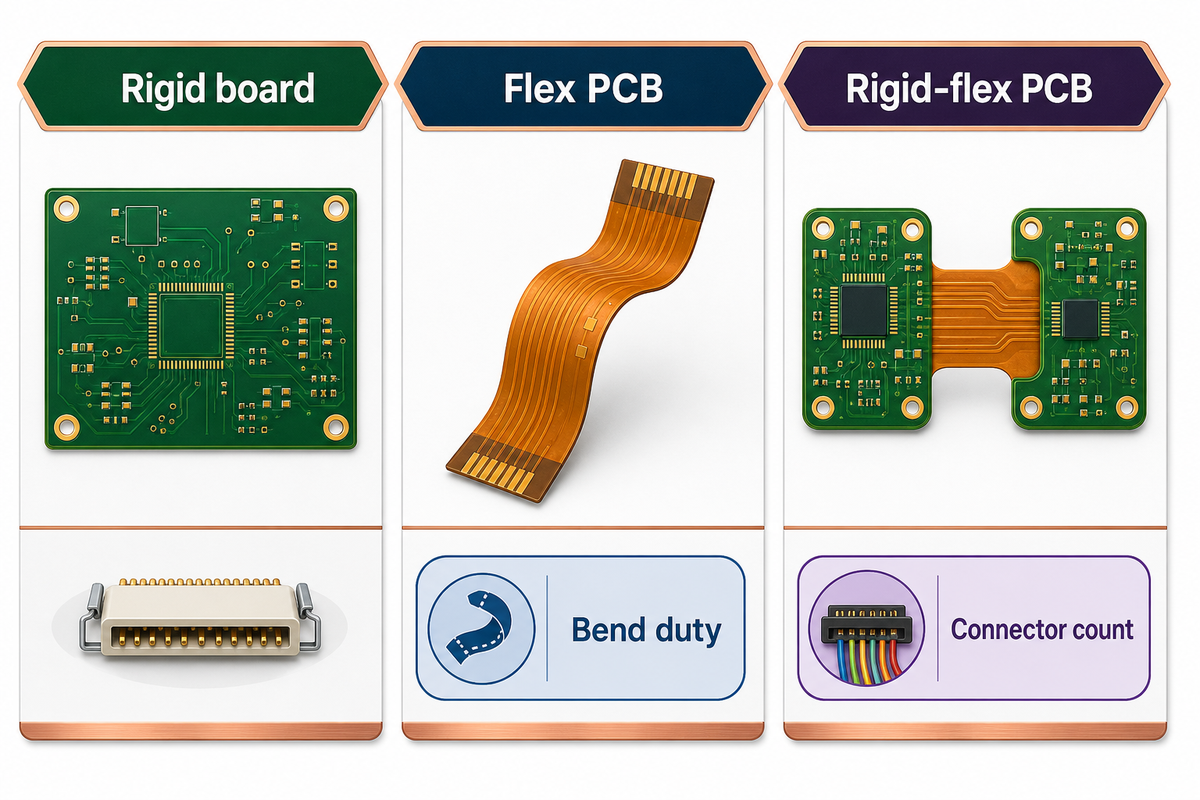
Flexible PCBs use bendable insulating films, usually polyimide, to carry copper circuitry through areas where a rigid PCB can’t fit. Rigid-flex PCBs combine rigid and flexible sections in one laminated printed circuit board, so components can sit on stable rigid zones while flex zones replace cables, jumpers, or board-to-board connectors.
Standards trail matters. Global Electronics Association’s standards update lists IPC-2223F as a May 1, 2026 release for flexible and rigid-flexible printed-board design, while IPC-6013E remains the qualification and performance anchor. Those revision dates confirm the document path; they don’t decide your IPC class, contract addenda, acceptance limits, or soldering process by themselves.
“Sectional design standard for flexible/rigid-flexible printed boards.”
What is rigid and flexible PCB?
Rigid PCB construction uses a stiff substrate such as FR-4. Flexible PCB construction uses a bendable substrate and coverlay in the bend area. Rigid-flex construction combines both in one build, reducing connector count but adding lamination, registration, transition-zone, and inspection control.
Some teams write rigid flex PCBs without the hyphen, but the RFQ should still separate the flexible circuit, flexible printed circuit board, and rigid circuit needs. Search terms such as rigid flex circuit boards, bendable circuit board, and rigid flex PCB design point to the same RFQ discipline. Compared to rigid construction alone, high reliability depends on the materials used and on how the flexible printed circuit is supported.
For search and RFQ clarity, treat circuit design considerations as one package: material callouts, bend duty, connector count, and inspection plan. A circuit manufacturer should distinguish flexible boards, PCBs and rigid-flex builds, traditional rigid layouts, and boards connected through flex tails before designing rigid-flex PCBs.
| Construction | Typical use | RFQ risk |
|---|---|---|
| Rigid board | Stable component platform, low motion | May need cables or connectors between boards |
| Flex PCB | Static fold, moving hinge, narrow path | Bend duty and material assumptions are often missing |
| Rigid-flex PCB | Compact assembly with rigid component islands | Higher stack-up and transition-zone complexity |
PCBark’s public flex page lists 1-10+ flex layers, 4-24+ rigid-flex layers, 0.050 mm trace/space capability, impedance-control support, and electrical testing. Use those as quote references, not as a substitute for your stack-up drawing.
Supplier screening note: PCBark states 16+ years in EMS, 500000 m2 annual PCB capacity, a 1-42 layer count range, IPC Class 2 and Class 3 build discipline, and visible ISO 9001, ISO 14001, UL, RoHS, REACH, and IPC-A-610 credentials. Treat these as supplier-screening inputs; the specific rigid-flex PCB build still needs stack-up approval, bend evidence, and test criteria.
Evidence note: A buyer comparing 3 constructions should send a clear use case before asking for price: rigid board, flex PCB, and rigid-flex PCB each change bend duty, connector count, inspection access, and test flow. PCBark’s flex PCB manufacturing page is the right internal hub for this first split.
The 6-Point Flex-to-Rigid-Flex Fit Matrix
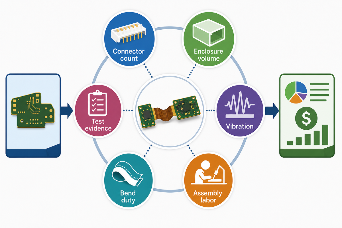
This 6-Point Flex-to-Rigid-Flex Fit Matrix keeps finance, engineering, and procurement in the same decision. Rigid-flex is usually justified when connector removal, enclosure space, vibration exposure, assembly labor, bend duty, and test evidence outweigh the extra fabrication and inspection work. Bare-board quote level alone is not the full cost picture.
Trade coverage reports that rigid-flex boards can use up to 60 percent less space than standard PCB approaches in some assemblies, mainly by removing connectors and connecting cables. Treat that figure as an enclosure-screening signal, not as a general engineering benchmark, because the published article does not define a measurement method or baseline assembly. Connector removal can reduce interface count, yet rigid-flex thermal-cycling evidence still points to stress in copper, vias, and rigid-to-flex transitions.
Benefits of flex are strongest when bends eliminate the need for connectors, making them ideal for compact products that still need serviceable test points. Best practices also check electromagnetic interference, shielding path, manufacturing equipment limits, and prototype and production handling before release.
| Decision point | Flex PCB fit | Rigid-flex PCB fit | Do not force rigid-flex when |
|---|---|---|---|
| Connector count | One flex tail or cable replacement is enough | Several board-to-board connectors can be removed | A simple connector is serviceable and stable |
| Enclosure volume | A bendable tail routes through a narrow path | Rigid islands save height and assembly stack space | The enclosure has room for a rigid board pair |
| Vibration | Useful when strain relief is defined | Useful when connector fretting is a known risk | Transition zones cannot be supported or tested |
| Assembly labor | Works when final folding is simple | Works when cables, screws, and manual routing can be removed | The build needs frequent repair or field replacement |
| Bend duty | Static fold or controlled dynamic motion | Static fold between rigid sections or limited motion | The hinge sees repeated motion without bend testing |
| Test evidence | Electrical test plus bend validation if needed | Electrical, impedance, inspection, and functional test data should align | No one owns the fixture, acceptance, or failure review |
Use PCBark’s rigid-flex PCB manufacturing page when the matrix points to integrated rigid and flexible sections.
Evidence note: The fit matrix has 6 decision points because board architecture is a system choice. One data point, such as up to 60 percent space reduction, can support the enclosure case, but it cannot prove reliability without bend, transition, assembly, and functional-test evidence.
Bend Radius, Flex Zones, and Stack-Up Rules
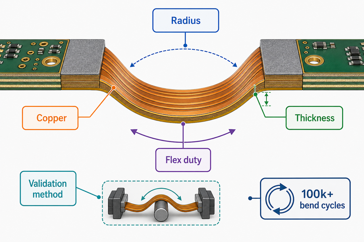
Bend radius is a stack-up decision, not a slogan. Flexibility changes with finished flex thickness, copper type, adhesive system, coverlay, number of flexible layers, bend length, and whether the bend happens once during installation or repeatedly during service. Ask for the bend assumption before you accept the fabrication quote.
How flexible are flex PCBs?
Flex PCBs can support tight static folds or repeated movement, but those are different designs. One-time folds can tolerate a different strain profile than a dynamic hinge. PCBark’s public calculator separates static, flex-to-install, and dynamic use, and it asks for construction and copper type rather than applying one universal multiplier. Drawing notes should also mark stiffener edges, solder areas, and any connector zone that must stay flat during assembly.
Procurement should treat an unmarked bend zone as an open engineering question, not as a harmless drawing detail.
0.050 mmPCBark stated trace/space capability
100k+PCBark stated dynamic bend-cycle capability
4-24PCBark stated rigid-flex layer range and 3.2 mm rigid-area option
Bend-Radius Evidence Packet: send the flex-zone drawing, inside bend radius, finished flex thickness, copper type, coverlay opening rules, adhesive choice, bend count, bend direction, stiffener edge locations, and test expectation. If the PCB design contains plated through holes or vias near the bend, ask the supplier to mark keep-out distance and reinforcement logic.
Rigid-flex thermal-cycling research found buried-hole copper plating failures under -55 °C to +125 °C cycling up to 6500 cycles. That doesn’t mean rigid-flex is unsafe. It means reliability claims must name the failure mode being removed and the new stress point being controlled.
For a numeric RFQ check, ask which values apply to your build: 0.08 mm, 0.20 mm, 0.05 mm, or 0.25 mm flex thickness; 0.5 oz, 1 oz, 2 oz, or 3 oz copper; 0.10 mm, 0.075 mm, or 0.050 mm trace/space; 1.5 mm bend keep-back; 0.5 mm via keep-out; and a 2.0 mm stiffener-edge review zone where the drawing calls for local support.
Evidence note: Bend evidence should include at least 5 fields before quote release: radius, thickness, copper, flex duty, and validation method. PCBark’s rigid-flex bend-radius calculator can help frame the first estimate, then DFM review should confirm the actual stack-up.
Material and Layer Decisions: Polyimide, Copper, Coverlay, Adhesive, Stiffeners
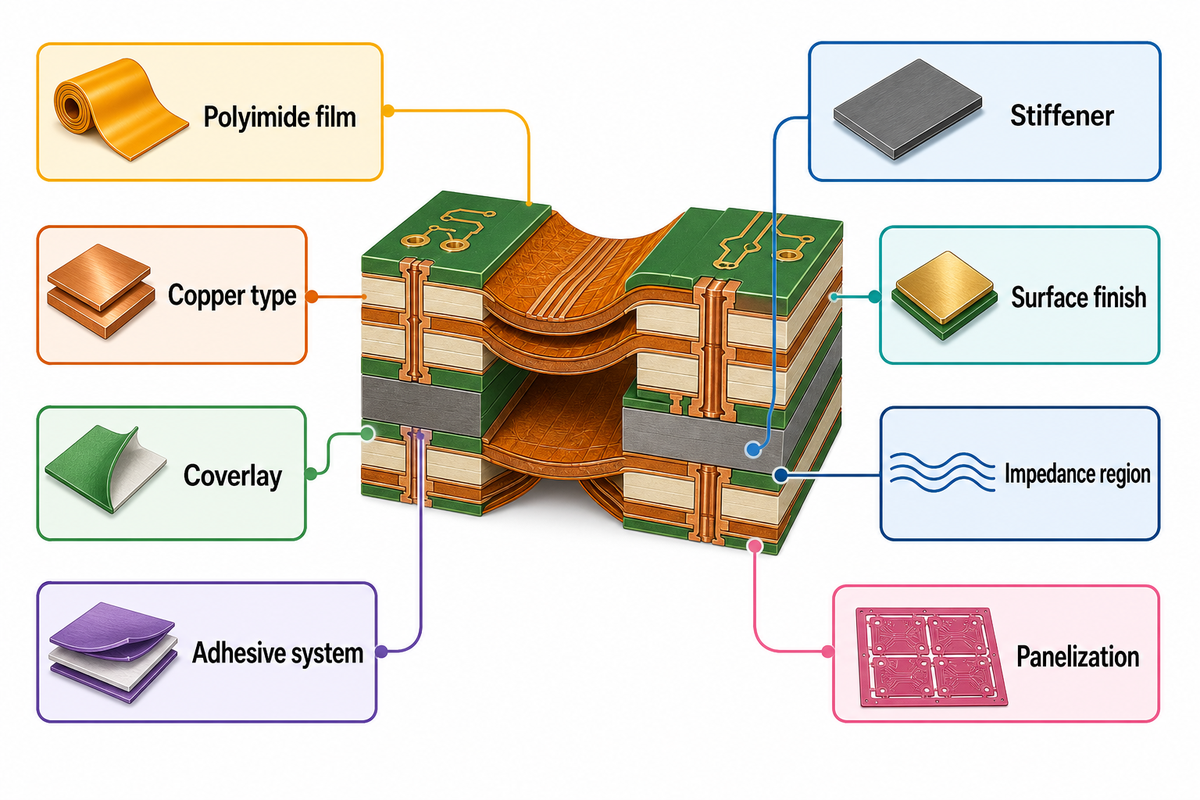
Material selection decides whether two flex and rigid-flex PCB quotes are really comparable; the current IPC revision trail is the external checkpoint before teams argue about price. Polyimide thickness, copper type, adhesive or adhesiveless construction, coverlay openings, FR4 rigid zones, stiffener material, and surface finish all affect bend strain, solder support, impedance, and inspection. Put assumptions in the RFQ instead of letting each supplier guess.
Polyimide flex is typically made of polyimide or related flexible materials. In the RFQ, the flexibility of the substrate explains why designs that can bend offer several advantages over traditional rigid layouts, but the benefit only holds when copper, coverlay, adhesive, and stiffener choices match the bend duty.
| Decision | Why it changes the quote | What to send |
|---|---|---|
| Polyimide film | Sets substrate flexibility and high temperature margin | Film thickness and temperature exposure |
| Rolled annealed copper | Often chosen for dynamic flex zones | Copper type, such as 0.5 oz or 1 oz, and bend-cycle target |
| Electrodeposited copper | Can fit static regions but needs bend review | Static or dynamic use note |
| Coverlay | Protects flex circuitry and changes access windows | Coverlay openings and solder lands |
| Adhesive system | Changes total thickness and bend strain | Adhesive or adhesiveless preference |
| FR4 rigid part | Carries components and connector loads | Rigid thickness and layer count |
| Stiffener | Adds local support for ZIF, solder, or connector regions | Material, thickness, and edge location |
| Surface finish | Affects solderability and storage | ENIG, OSP, immersion tin, or other finish callout |
| Impedance region | Affects copper geometry and dielectric control | Target impedance, tolerance, coupon requirement |
| Panelization | Affects handling, yield, and assembly support | Array, rails, fiducials, and breakaway plan |
This table prevents quote mismatch. One supplier may assume adhesiveless material and RA copper; another may assume lower-cost static flex construction.
Ensuring that the flexible sections can withstand repeated bending and flexing without mechanical failure is essential in dynamic products; flexible sections can be challenging to qualify when the drawing lacks bend count, radius, and copper type. Test notes should also say whether the flexible sections can withstand repeated forming after assembly and whether fixture plans hold the board consistently.
Evidence note: A 10-row stack-up table gives procurement a cleaner comparison than a short feature list. RFQ reviews should name material, copper, coverlay, stiffener, finish, and impedance assumptions before teams compare unit prices or lead times across suppliers.
When NOT to Use Flex or Rigid-Flex PCB
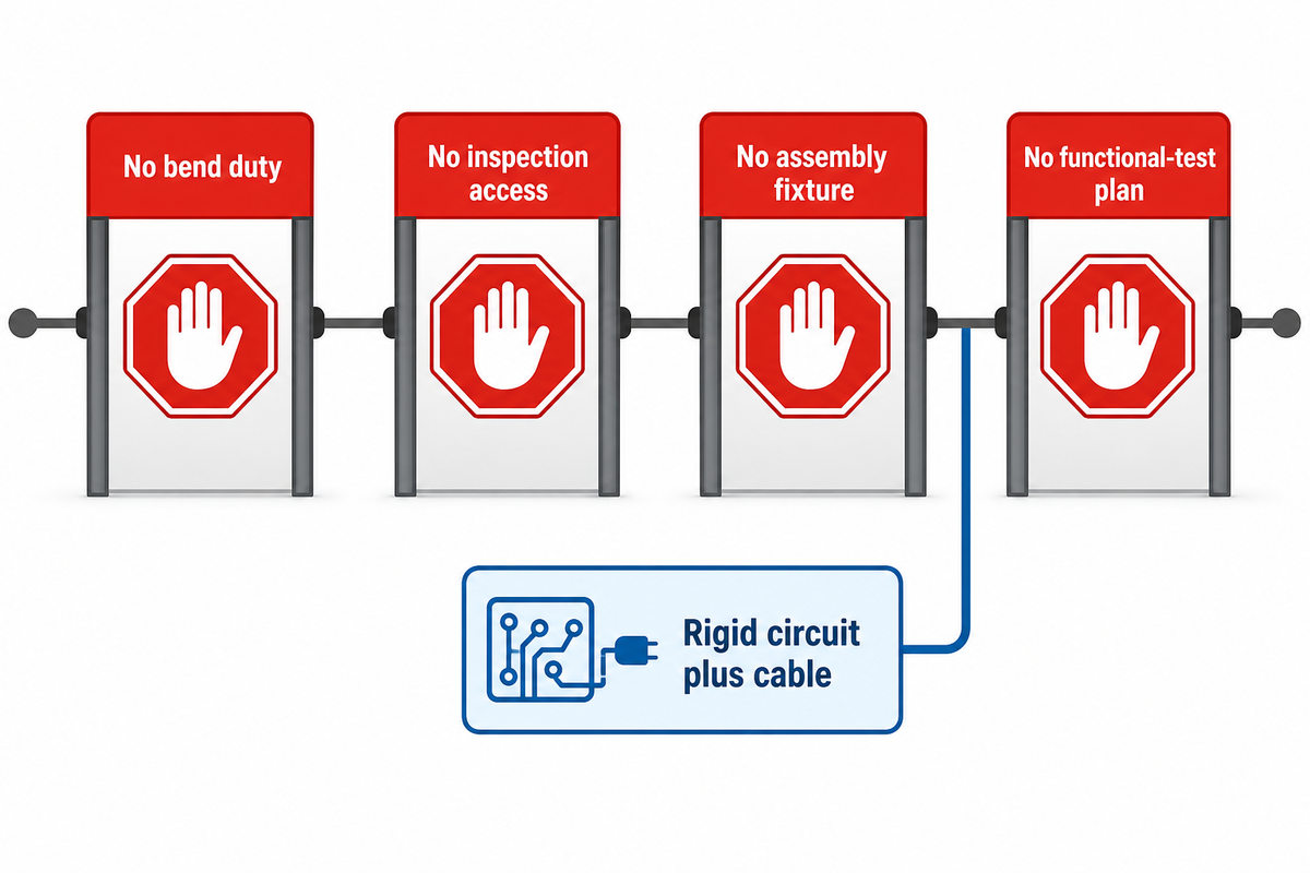
Flex or rigid-flex PCB design is the wrong move when material, stack-up, and stiffener choices cannot produce a documented gain from bending, connector removal, size and weight reduction, or vibration control; rigid-flex failure research is a reminder that connector removal does not erase copper-fatigue risk. Compact enclosure pressure is not enough. If the bend area cannot be documented, inspected, or tested, the more advanced circuit board can add risk instead of removing it.
What are the downsides of using flexible PCBs?
Flexible PCBs can cost more than simple rigid PCBs and fail when bend zones, stiffeners, adhesive, coverlay, solder joints, or handling fixtures are planned late. Rigid-flex printed circuit boards add lamination and transition-zone control, so the design needs a measurable reason to earn that process work.
Do
- Choose flex when a bendable path removes mechanical strain.
- Use rigid-flex when rigid and flexible sections remove connectors and assembly steps.
- Ask for bend, inspection, and test evidence before release.
- Use a stiffener when localized support is enough.
Don’t
- Use rigid-flex only because the product looks compact.
- Put vias, solder joints, or stiffener edges into unknown bend zones.
- Compare quotes when stack-up assumptions differ.
- Claim reliability from connector removal alone.
Reject flex or rigid-flex when a rigid circuit and short cable provide better repair access, lower field replacement cost, or safer thermal separation. Volume production exposes whether operators can fold, fixture, inspect, and test the assembly the same way every time.
Evidence note: The negative-use screen should name at least 4 stop conditions: no documented bend duty, no inspection access, no assembly fixture, and no functional-test plan. Those conditions matter more than a single board-price comparison because failure can move from a connector into copper or transition zones.
DFM and RFQ Data PCBark Needs Before Quote
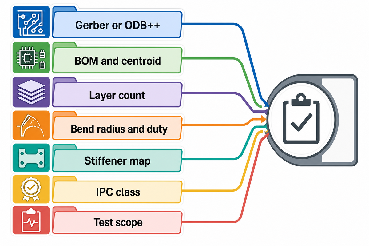
A useful RFQ gives PCBark the data needed to quote the same product you intend to build. Gerbers can start fabrication review, but assembly needs the BOM, centroid, component orientation, sourcing constraints, and test plan. Rigid-flex work also needs bend zones, stiffeners, stack-up intent, and class expectations tied back to the current IPC document path.
Use the Rigid-Flex RFQ Data Pack before you request pricing. It separates quote data from final validation data, so the first DFM response can flag risk instead of guessing. PCBark’s DFM analysis workflow covers trace/space, drilling, annular ring, copper-to-edge, solder mask, silkscreen, and engineer review inputs.
For flexible electronics, document the manufacture route, signal integrity target, FR-4 island thickness, solder mask versus coverlay boundary, prototype handling, cost owner, and each electrical connector datum before production release.
Rigid-Flex RFQ Data Pack – copy these into your quote request:
| Parameter | Recommended range | Why it matters | How to verify |
|---|---|---|---|
| Gerber or ODB++ package | Final revision plus drawing | Defines copper, drill, mask, coverlay, and outline | DFM checklist and revision lock |
| BOM and centroid | Required for assembly | Separates bare board from turnkey PCBA scope | BOM audit and placement file review |
| Layer count | 1-10+ flex; 4-24+ rigid-flex per PCBark public pages | Sets lamination and routing scope | Stack-up drawing approval |
| Finished flex thickness | State actual target in mm | Controls bend strain | Stack-up review and bend packet |
| Bend radius and bend duty | Static, flex-to-install, or dynamic | Prevents one-size-fits-all bend assumptions | Bend drawing and validation note |
| Stiffener map | Material, thickness, and edge distances | Protects solder and connector areas | Mechanical drawing review |
| IPC class and acceptance | Class 2 or Class 3 when required | Changes inspection and acceptance expectations | Contract review and inspection plan |
| Test scope | E-test, AOI, impedance, functional test as needed | Links fabrication to product-level risk | Test fixture and report requirement |
Evidence note: An RFQ data pack with 8 parameters reduces ambiguity before DFM. Gerbers define copper and drilling, but BOM, centroid, bend duty, stiffener data, IPC class, and test scope decide whether the quoted rigid-flex PCB matches the final assembled product.
Assembly, Sourcing, and Functional Test Risks
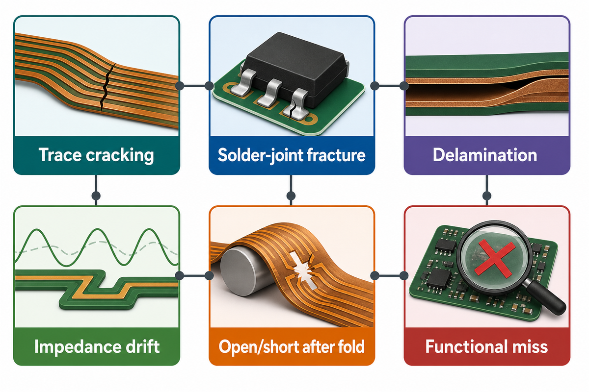
Flex and rigid-flex PCBs can pass bare-board fabrication and still fail during assembly, handling, or field use. Risk moves into solder support, fixture design, strain relief, component sourcing, reflow exposure, inspection access, and functional test coverage. Treat PCB fabrication and PCB assembly as one plan when the board must bend.
IPC-A-610J is the current 2024 assembly acceptance context for electronic assemblies. It should be paired with IPC-6013E and the purchase contract, not used as a loose quality slogan. PCBark’s flex assembly page lists risks such as trace cracking, solder-joint fracture, delamination, popcorning, bow/twist, misplacement, and rework reliability.
| Risk | Where it appears | Evidence to request |
|---|---|---|
| Trace cracking | Bend zone or transition | Bend test or failure review trigger |
| Solder-joint fracture | Stiffener or connector region | Fixture and strain-relief review |
| Delamination | Reflow or thermal stress | Thermal profile and inspection data |
| Popcorning | Moisture-sensitive assembly | Bake, storage, and reflow controls |
| Tombstoning | Small passive components | Stencil and placement review |
| Misplacement | Flexible carrier handling | Panel, tooling, and fiducial plan |
| Impedance drift | Controlled circuit regions | Coupon, TDR, or impedance report |
| Open/short after fold | Final mechanical forming | Electrical test after forming when needed |
| Functional miss | Finished PCBA | Functional fixture, limits, and sampling plan |
PCBark’s flex PCB assembly service is relevant when the buyer wants fabrication, SMT assembly, sourcing, AOI, X-ray, flying probe, and functional testing in one chain. Exact acceptance data still belongs in the RFQ.
Evidence note: A 9-row risk register isn’t paperwork. Each row tells the supplier whether to provide inspection evidence, electrical data, fixture review, or functional-test output. For rigid-flex products, acceptance starts before SMT because bending and support fixtures can change solder-joint stress.
Prototype-to-Volume Transfer Plan
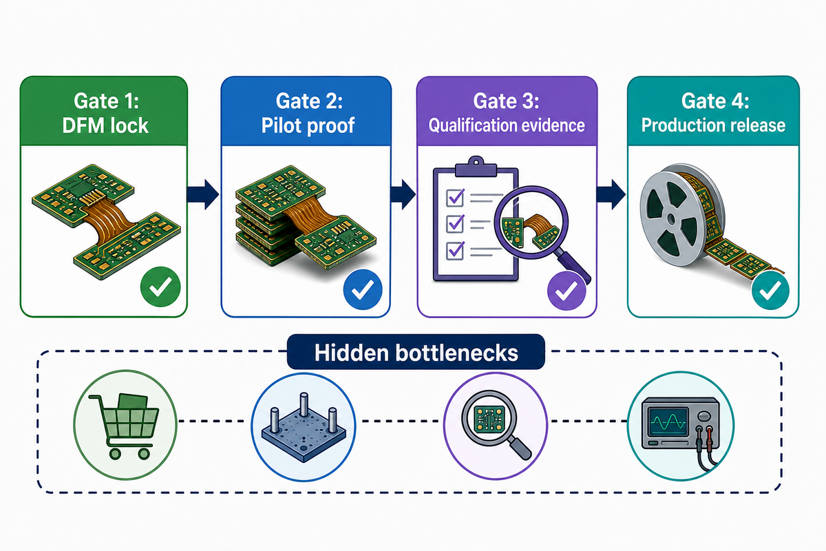
A prototype proves that the circuit can work once. Volume release proves that the same flex or rigid-flex circuit can be manufactured, assembled, inspected, folded, sourced, and tested repeatedly. Below, the 4-Gate Prototype-to-Volume Transfer Plan turns prototype success into controlled transfer gates before purchasing commits to production quantities.
UL’s PCB reliability testing page lists production-board testing, environmental conditioning, microsection and failure analysis, interconnect stress testing, signal integrity, and CAF testing. Buyers don’t need every test on every product, but the transfer plan should say which evidence answers the actual failure mode.
- Gate 1: DFM lock – freeze stack-up, bend zones, stiffeners, panel support, and IPC class before the pilot build.
- Gate 2: Pilot proof – build enough units to observe fabrication yield, assembly handling, and post-form electrical behavior.
- Gate 3: Qualification evidence – match test methods to the real risk, such as bend cycling, thermal exposure, impedance, or functional limits.
- Gate 4: Production release – lock BOM alternates, fixture plan, inspection records, test reports, and change-control rules before volume orders.
Hidden Bottleneck Map: Prototype-to-Volume Transfer: sourcing can fail after the electrical design works; reflow support can fail after the bare board passes; inspection can fail after folding; fixtures can fail when the enclosure blocks access. Map those bottlenecks before production release.
Evidence note: The 4-gate transfer plan asks for DFM lock, pilot proof, qualification evidence, and production release data. That sequence fits quick-turn prototypes and higher-volume PCB manufacturing because it catches sourcing, fixture, and functional-test gaps before they become repeat defects.
Buyer Outlook: Smaller Products, Higher Reliability Evidence
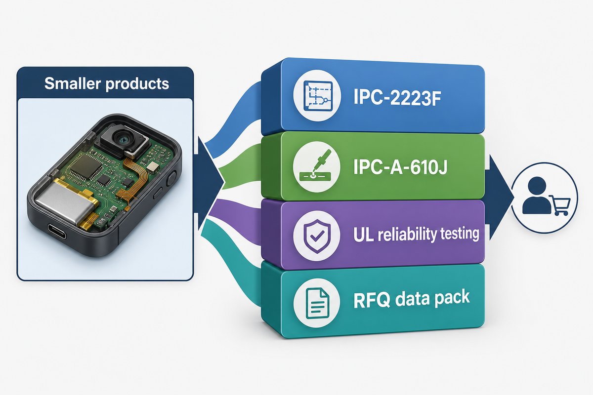
Smaller electronics, wearables, medical devices, aerospace assemblies, and dense industrial controls keep pressure on flex and rigid-flex PCB technology. Smaller products do not make rigid-flex automatically right. They raise the evidence burden for bend zones, assembly handling, and acceptance testing.
Patent activity can show technical attention, but WIPO’s 2026 report cautions that patent data is imperfect: not all inventions are patented, patenting rates vary, patent quality differs, and citations need care. Treat 2024 and 2025 rigid-flex patent examples as technical signals, not proof of market adoption.
For buyers, the stronger trend is evidence discipline. IPC-2223F gives a current design-document anchor in 2026. IPC-A-610J gives a 2024 assembly acceptance context. UL highlights reliability testing categories for more complex boards. PCBark’s role is to connect those expectations to manufacturable stack-ups, sourcing, assembly, and functional testing.
Key takeaway
Choose flex or rigid-flex when the product earns the added process control through documented bend duty, connector reduction, assembly support, and test evidence; do not buy a 4-24 layer rigid-flex capability claim without a matching RFQ data pack.
FAQ
Are rigid-flex PCBs more reliable than board-cable assemblies?
They can reduce connector and cable interfaces, but that does not prove reliability. Rigid-flex also creates transition-zone, via, copper-fatigue, assembly-handling, and thermal-cycle risks. Ask which failure mode is removed, which new stress point is controlled, and whether testing covers bend, thermal, electrical, and functional behavior after forming in the enclosure itself.
What data should I send for a rigid-flex PCB quote?
Send Gerbers or ODB++, stack-up intent, bend-zone drawings, radius, flex thickness, copper type, stiffener map, IPC class, BOM, centroid, impedance targets, and test expectations. If the product is not frozen, give a minimum radius, expected motion, component height limits, and the acceptance data you need after fabrication and assembly review approval.
Is flex PCB assembly different from rigid PCB assembly?
Yes. Flex PCB assembly often needs handling support, fixture control, stiffener review, solder-joint strain review, and post-form test planning across fabrication, assembly, sourcing, and functional test. Assemblers should know where the board bends, which areas must stay flat, and whether electrical or functional test happens before or after folding. For example, a 0.5 mm via keep-out, 1.5 mm bend keep-back, 0.050 mm trace/space target, or 235 °C reflow ceiling can change tooling, panel support, and inspection order. Those details belong in the RFQ, not in a late production email.
Send PCBark a Buildable Flex or Rigid-Flex Data Pack
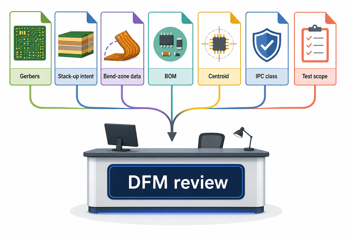
PCBark can review DFM, fabricate flex and rigid-flex boards, source components, assemble SMT, and run functional testing. Send your Gerbers, stack-up intent, bend-zone data, BOM, centroid, IPC class, and test scope to get a quote that reflects the product you plan to ship.
References & Sources
- Global Electronics Association: recently released IPC standards and documents
- Global Electronics Association / IPC-2223F product listing
- IPC-6013E product listing
- IPC-A-610 Revision J listing
- UL: PCB safety compliance and reliability testing services
- WIPO World Intellectual Property Report 2026: patent data caution
- Microelectronics Reliability: thermally stressed rigid-flex printed circuit boards
- Assembly Magazine: selective soldering for rigid-flex PCBs
WHY WE WRITE THIS
About PCBark Engineering Insights
PCBark shares technical PCB fabrication and assembly guides based on real engineering review and manufacturing experience. We help teams compare materials, stackups, DFM risks, component sourcing, inspection plans, and production routes before they move from prototype to volume builds.
16+ yrs EMS experience
1-42 PCB layers
500,000 m2 annual PCB capacity
IPC Class 2/3 build discipline
DFM + test review







![16-24 Layer PCB: Stackup, Lamination & Design Guide [2026]](https://pcbark.com/wp-content/uploads/2026/07/16-24-layer-pcb-guide-featured-2-150x150.png)


