
Get in touch with PCBark Company

PCBark · High-Reliability EMS · AS9100 / IPC J-STD-001 Class 3
Circuit Card Assembly (CCA) for Defense & Aerospace
Class 3 Reliability CCA Built To J-STD-001 And IPC-A-610
PCBark provides turnkey SMT, through-hole, and rigid-flex CCA’s built and inspected to IPC J-STD-001 and IPC-A-610 Class 3 – the gold-standard that determines if a board dies in the field or lives up to its promise. All our builds have 100% traceability, a clear view of the price, and multiple inspection steps before we deliver your finished PCBA’s.
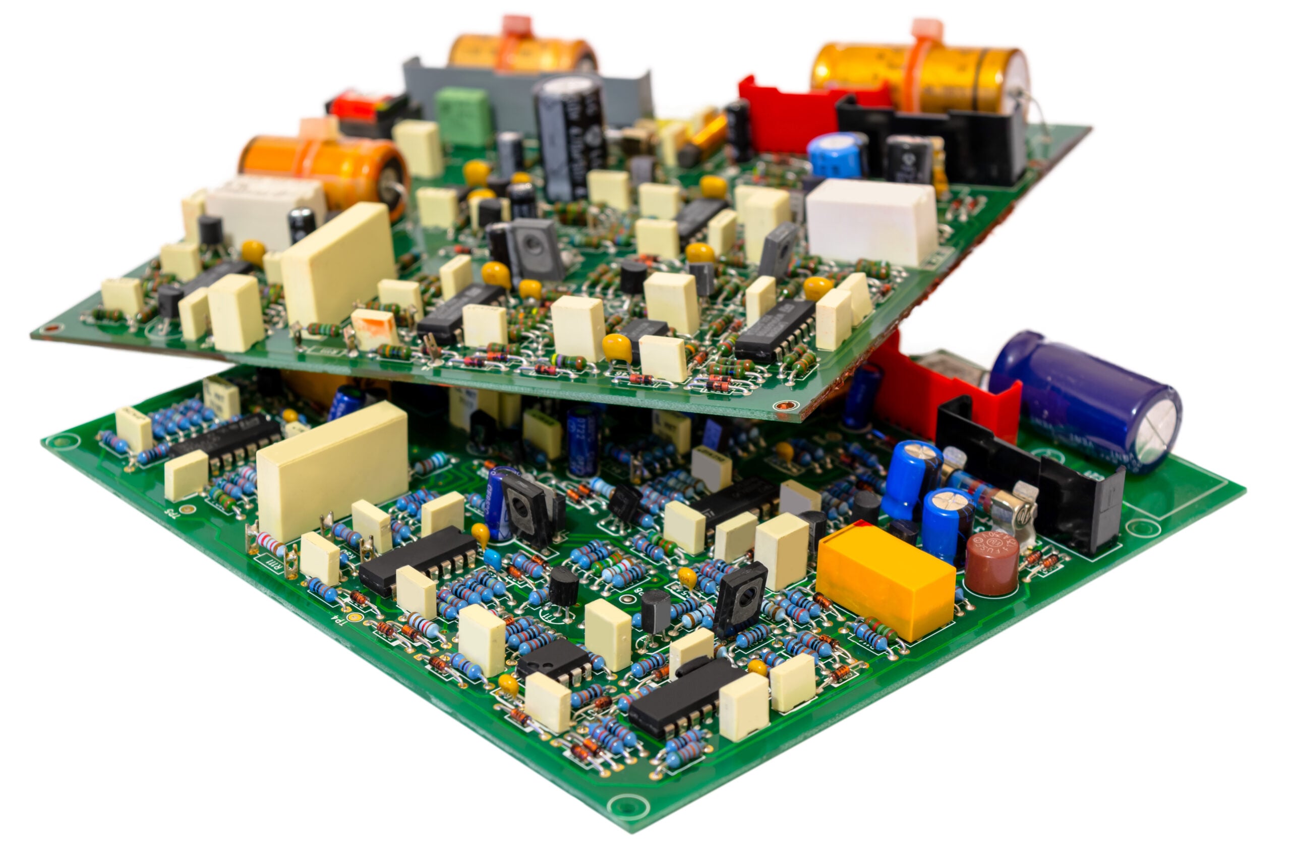
/// FACILITY CAPABILITY
01
Class 3
IPC J-STD-001 & IPC-A-610 acceptance
02
AS9100
Aerospace QMS + ITAR registered
03
SMT · TH · Rigid-Flex
Mixed-technology CCA
04
16+ yrs
EMS manufacturing experience
05
Proto → Volume
Quick-turn to production
06
Full Test
AOI · X-ray · ICT · functional
For Engineers · Procurement · Program Managers
High-Reliability Circuit Card Assembly for Mission-Critical Systems
A circuit card assembly (CCA) is what it’s called when electronic components are attached to a printed circuit board (PCB); it’s technically the same product you might know as a PCBA, PCB assembly, or populated printed wiring board in older specs. But it matters a great deal whether the CCA was constructed for a consumer-friendly gadget or an aircraft under fire, and if your product will perform as it should in any situation, it must be Class 3 compliant.
/// 01
Why “Reliability” CCA?
High failure rates typically appear long after boards are shipped – a near-miss soldering process, a substandard component with an eventual drift in value, or an omitted layer by a less reputable manufacturer are just a few of the defects found in the field that are not visible during visual or X-ray inspection. When failure isn’t an option and that failed board was meant to be on a combat mission, the true price paid is more than just a lost product. It’s a lost operation.
/// 02
We Make High-Reliability CCA’s a Reality
PCBark builds CCAs to close that gap. Every PCB assembly is produced and inspected to IPC J-STD-001 and IPC-A-610 Class 3 acceptance, backed by automated optical inspection (AOI), X-ray for hidden joints, in-circuit and functional test, and full lot traceability from component sourcing through final electrical test. The rest of this page lays out exactly how we build, how Class 3 differs from commercial-grade work, what we have proven in the field, the certifications behind it, and a procurement section that — unlike most of our competitors — tells you what actually drives your price.
PCBark CCA Capabilities — Build Specs & Service Tiers
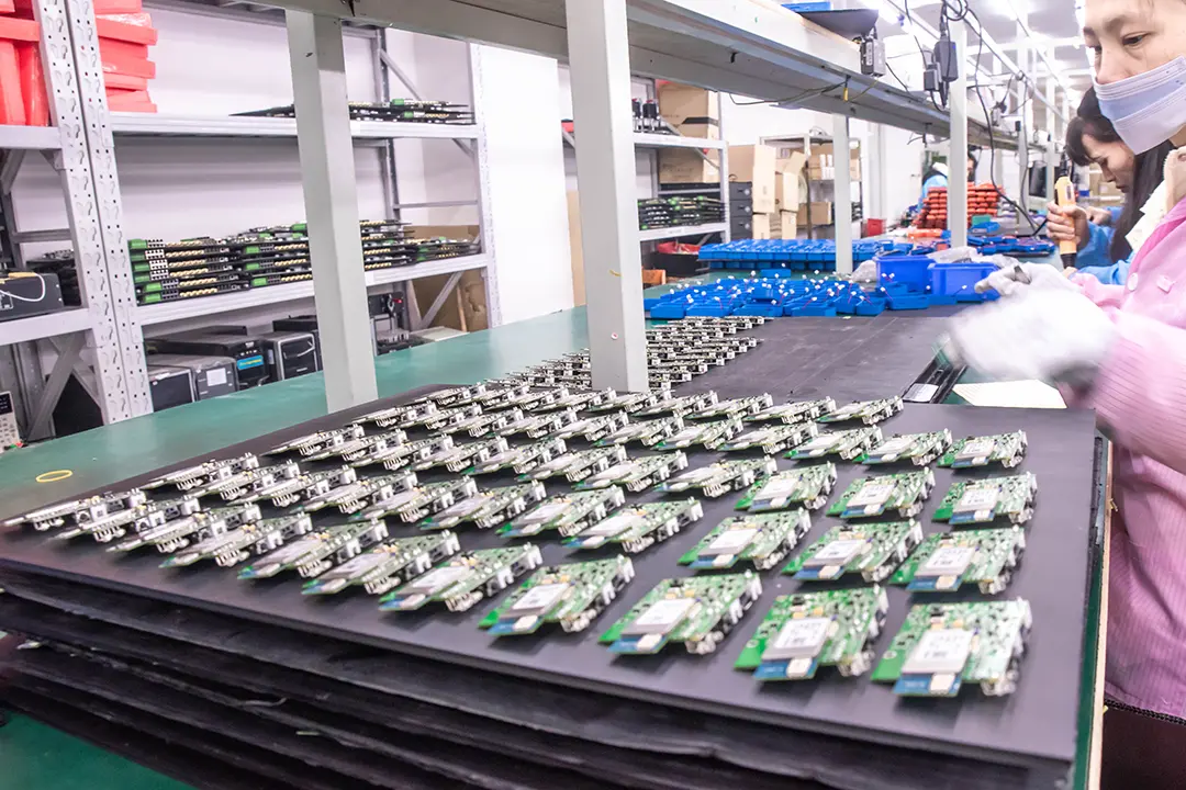
Our one-stop process manages your product from concept to delivery: a DFM (design-for-manufacturing) review to catch potential problems before they occur, components sourced from approved franchised distributors, fabrication of any needed bare PCB’s, the actual circuit card assembly, and rigorous functional testing – all under a single roof. Single-source accountability eliminates finger-pointing between fab house and assembler if a root-cause analysis is needed. The base material depends on your application; from FR-4 and high-Tg to polyimide we use the right laminate for thermally stressed defense applications and support the assembly capabilities listed below, a collection often found in mission-critical boards.
/// State-of-the-Art CCA Technologies
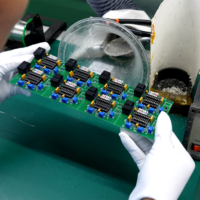
SMT Assembly
Fine-pitch surface mount (SMT) down to 01005, placed with high-precision robotics, reflowed in accurately profiled, monitored ovens, and verified by SPI (solder paste inspection).
01005 · fine-pitch BGA · QFN · SPI + AOI
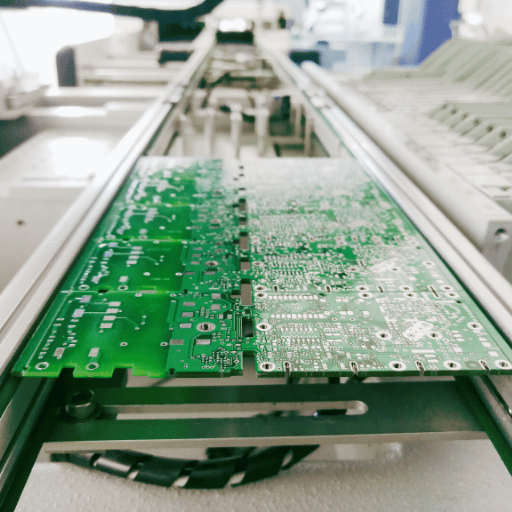
Through-Hole & Mixed
Through-hole technology with selective and wave soldering is still a critical requirement in some military builds for mechanical strength. Mixed-technology PCB assembly — surface mount plus through-hole — is completed in a single build.
Selective solder · wave · mixed-tech
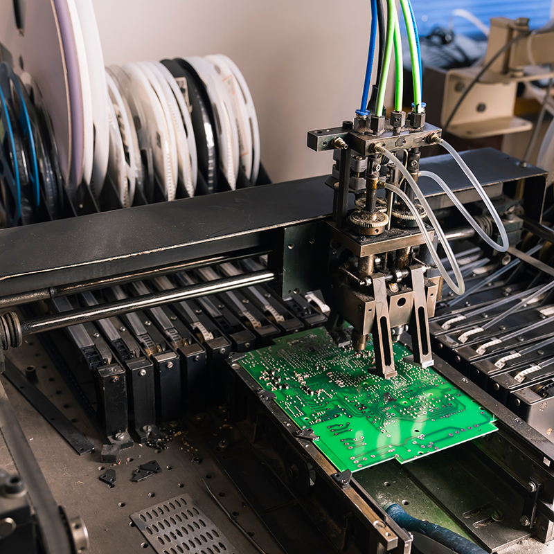
Rigid-Flex & HDI
Flexible, high-density interconnect (HDI) CCA’s that often eliminate the need for wiring and interconnects. Flexible CCA’s are ideal for tightly packaged avionic systems, robotics, and handheld military hardware where vibration and flex are issues.
Rigid-flex · HDI · blind/buried vias
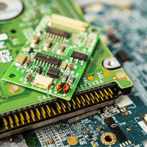
Conformal Coating & Box Build
Conformal coating shields the printed circuit board in harsh military and airborne environments, plus higher-level box-build and cable-assembly integration so the CCA arrives as a tested sub-assembly, not a bare board.
Acrylic/urethane/parylene · box build
Engineering Note — Why DFM happens before quoting
We run DFM on your package before we price it, not after you commit. Catching an unmanufacturable annular ring, an unsourceable part, or a footprint error at the data stage costs an email; catching it after a Class 3 build is qualified costs a re-spin. Buyers on hardware forums consistently rank a contract manufacturer that “wants to do DFM and gives you full costing for review” above one that simply quotes fast – because the fast quote is the one that comes back wrong.
/// Service Tier Decision Matrix
Most programs move through these tiers in sequence. The matrix maps each tier to the build profile it fits – use it to match your stage to the right line, then send the package for an exact quote.
| Service Tier | Typical Volume | Best Fit | Build Class | Test Depth |
|---|---|---|---|---|
| Prototype / Quick-Turn | 1–25 | Design validation, first articles | Class 2 or 3 | AOI + functional |
| Low-Volume Hi-Rel | 25–500 | Defense / aerospace production | Class 3 | AOI + X-ray + ICT + functional |
| Series Production | 500+ | Sustained programs | Class 2 or 3 | AOI + X-ray + sampling ICT |
| Box Build / Integration | Any | Tested sub-assemblies | Per CCA spec | System-level functional |
IPC Class 3 vs Class 2 — Why the Standard Decides Field Survival
The single most consequential line on a CCA purchase order is the build class. IPC defines three classes; defense, aerospace, and life-support hardware are Class 3 – assemblies where continued performance is required and downtime cannot be tolerated. The differences are not marketing tiers. They are concrete, inspectable, measurable acceptance criteria under IPC-A-610 and IPC J-STD-001, and they are where a commercial-grade PCB assembly and a high-reliability one diverge.
/// Acceptance Criteria Matrix
| Acceptance Criterion | Class 2 (commercial / dedicated) | Class 3 (high-reliability) |
|---|---|---|
| SMT side-fillet solder | 75% wetting | 100% wetting |
| Plated through-hole copper | 0.8 mil (20 µm) | 1.0 mil (25 µm) |
| Plating void allowance | 1 void per 5 holes | Zero voids |
| Internal annular ring | 0 mil minimum | 1 mil minimum |
| Conductor-width reduction | up to 30% | up to 20% |
| PTH circumferential wetting | 180° | 270° |
| Inspection method | Mainly visual | Microscopic + 100% inspection |
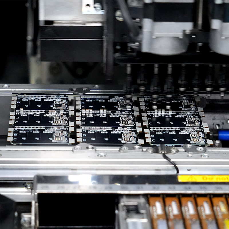
/// INSPECTION
Read the table as a survival margin, not a spec sheet. The jump from 75% to 100% side-fillet wetting is the difference between a joint that holds nominal vibration and one rated for MIL-STD-810 random-vibration and thermal-cycling profiles. Zero plating voids and a thicker barrel are what keep a plated through-hole conductive through hundreds of thermal cycles instead of cracking open. None of this is visible to a buyer holding the finished board – which is exactly why the inspection method line matters. Class 3 is verified under magnification and, for hidden BGA and via-in-pad joints, by X-ray. A lead-free joint can look identical whether it is good or cold; assemblers who inspect “mainly visually” ship the difference.
Ready to see how a Class 3 build changes the numbers for your board?
Request a Class 2 vs Class 3 build comparisonProven in the Field — Reliability Outcomes & Application Industries
The reason Class 3 acceptance and full inspection earn their cost is simple arithmetic: on a high-reliability program, the cost of a single field failure dwarfs the per-board price difference between a commercial and a high-reliability build. A board reworked at the assembler is an inconvenience; a board that escapes to a deployed system is an investigation, a stand-down, and sometimes a recall across the whole lot.
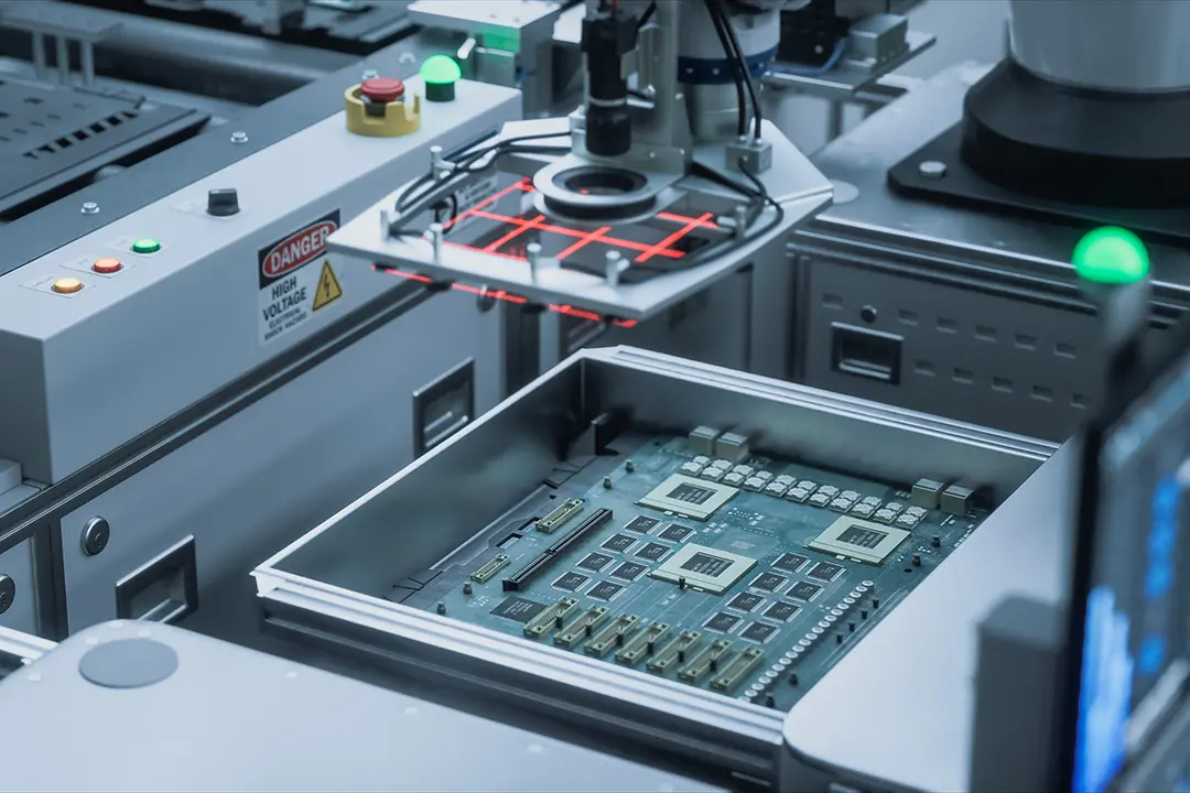
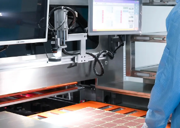
That is why our test strategy front-loads detection: SPI catches paste defects before parts are placed, AOI catches placement and joint defects before reflow leaves the line, X-ray catches what no visual inspection can see under a BGA, and ICT plus functional test catch the electrical escapes. For programs that have switched to PCBark from lower-cost assemblers, the recurring driver is not headline price – it is the elimination of the quality escapes and the “we won’t fix it” responses that made the cheaper board more expensive in the end.
Read more Show less
10–100×
The widely cited “rule of ten”: the cost to find and fix a defect rises by roughly an order of magnitude at each stage it escapes — from bare-board test, to assembly, to system integration, to the field.
Industry reliability principle (cost-of-quality / “1-10-100 rule”). PCBark inspection strategy is built to catch defects at the earliest stage. Request an application-specific cost-of-failure analysis for your program.
Where these CCAs run
This same high-reliability build profile is shared with a similar set of demanding customers:

01
Avionics & Flight Systems
Cabin and flight-control electronics where thermal cycling and vibration are continuous, not occasional.
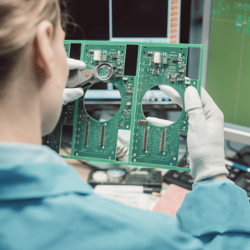
02
Radar, C2 & Electronic Warfare
Signal-processing and command-and-control assemblies where intermittent joints are mission-ending.

03
Defense Sensors & Power
Sensor front-ends and power conditioning subjected to shock, humidity, and wide temperature swings.
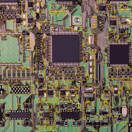
04
Industrial Hi-Rel
Medical, energy, and instrumentation hardware that borrows the same Class 3 discipline.
Certifications & Compliance
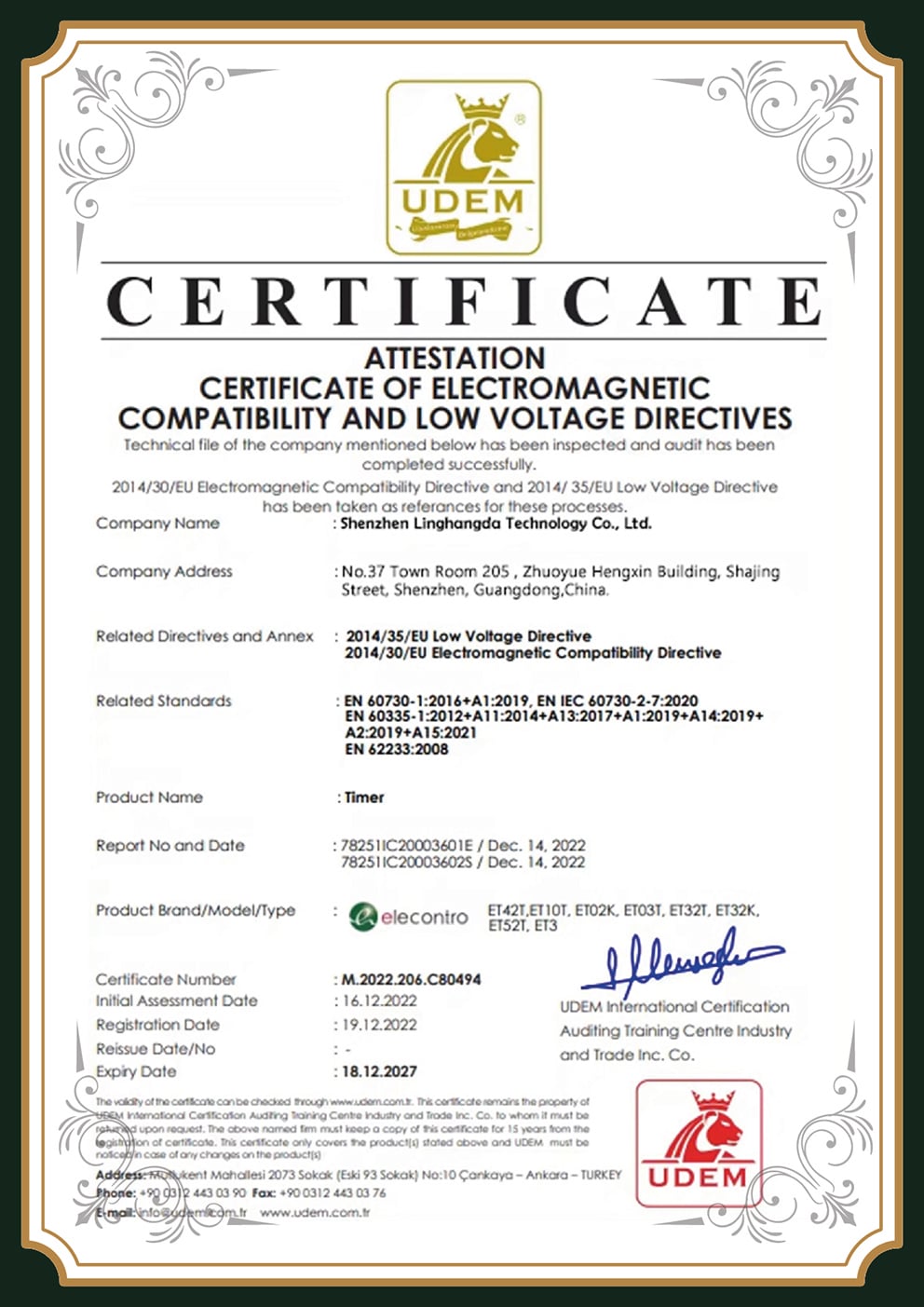
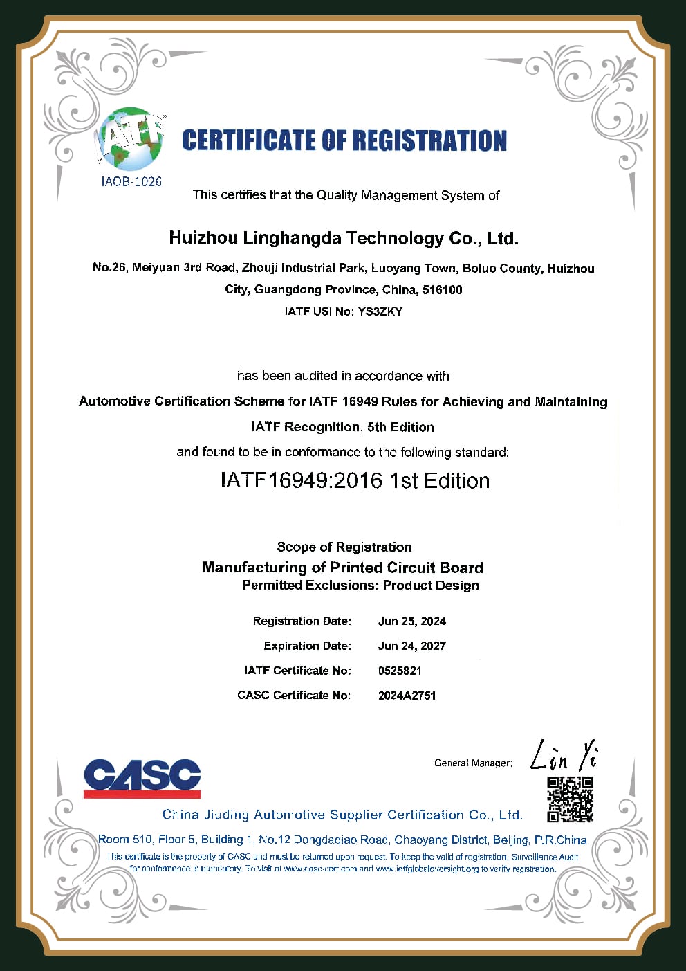
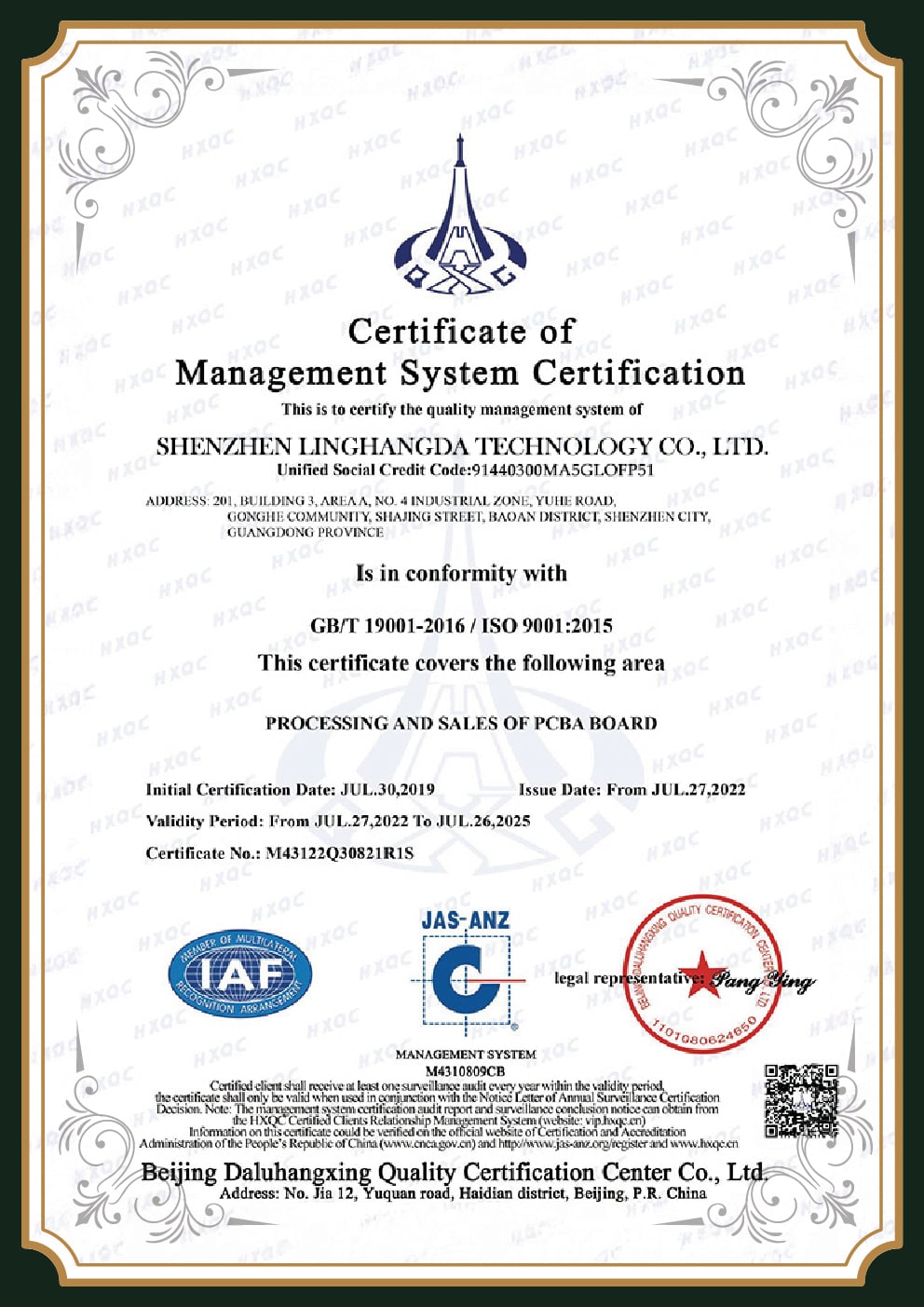
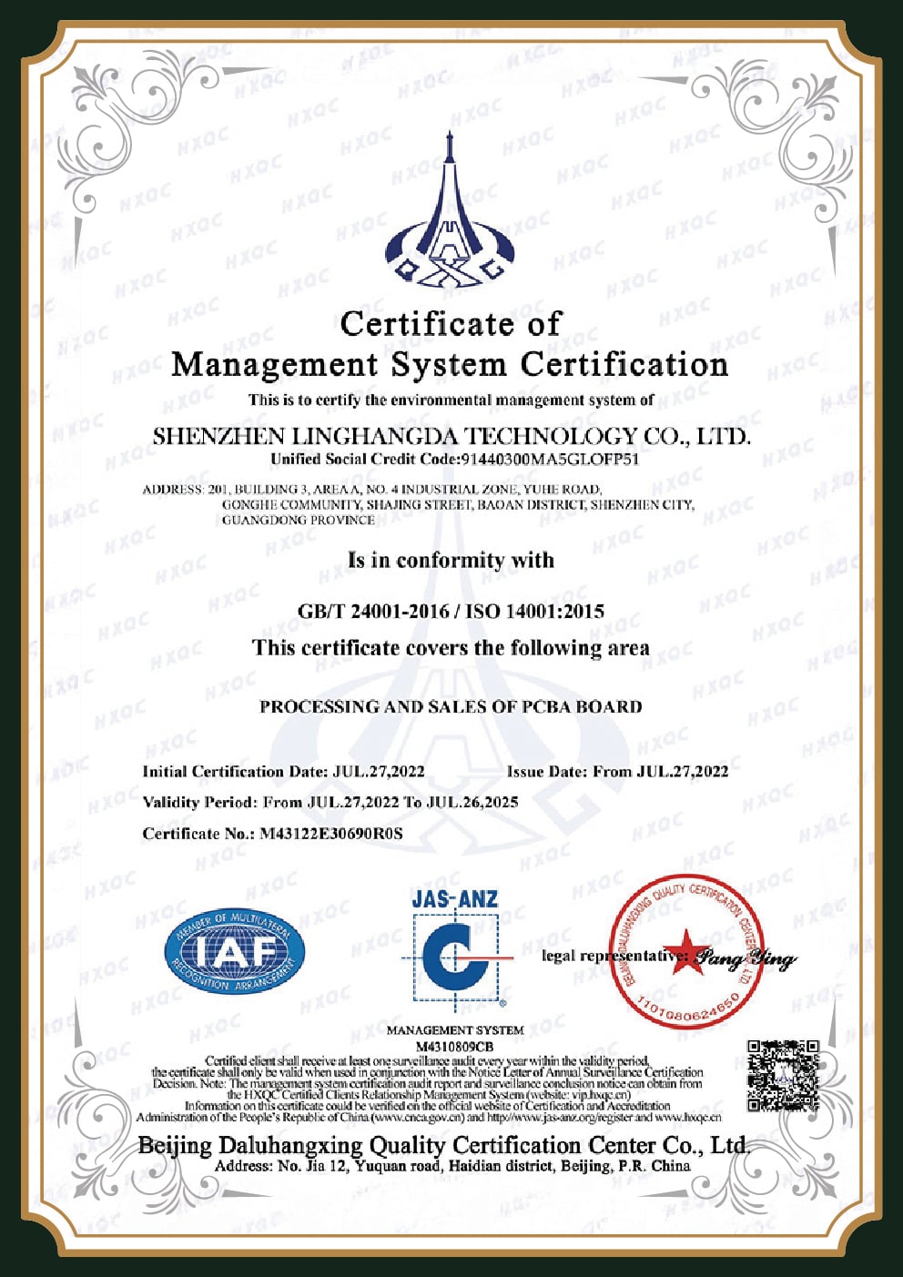
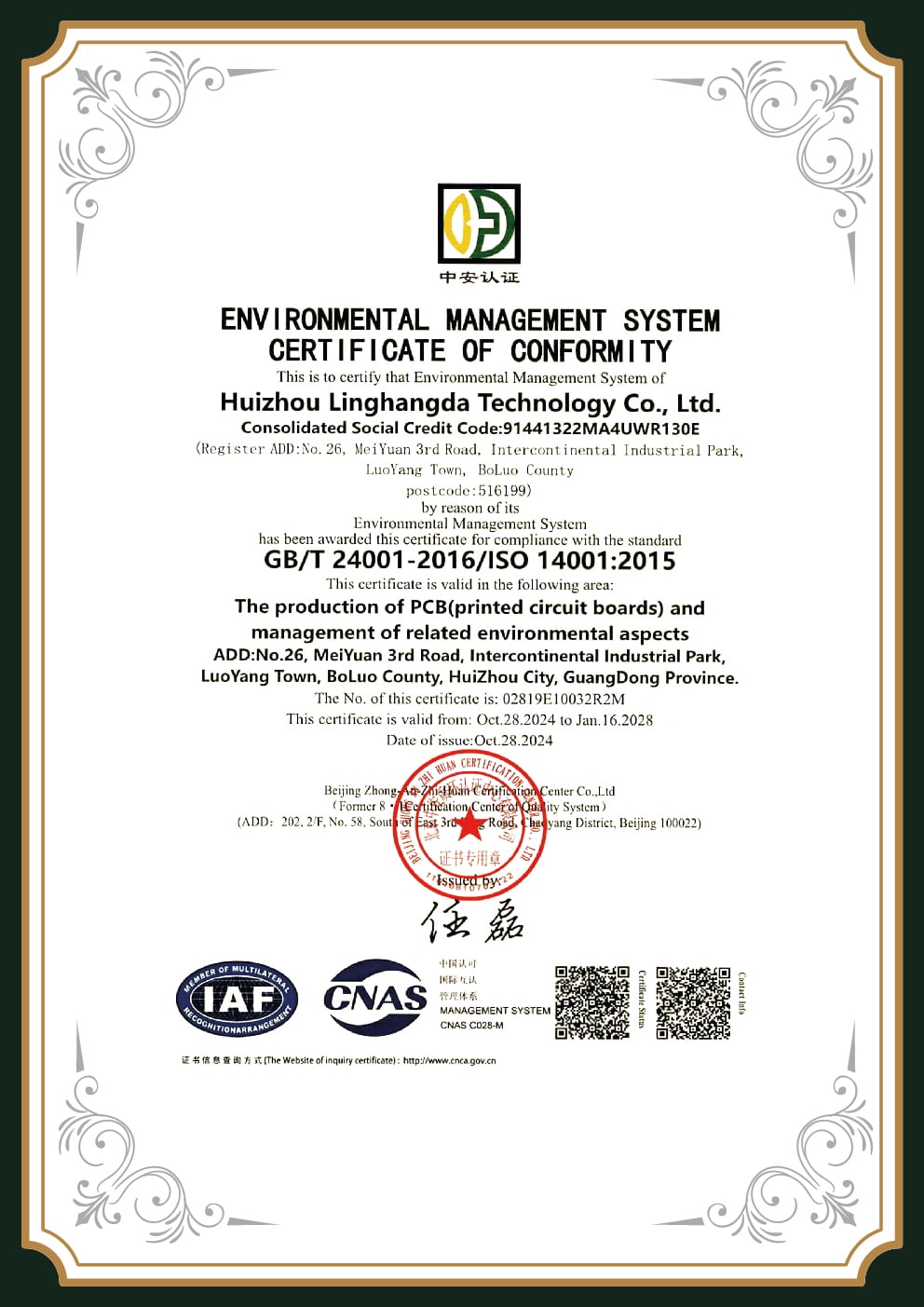
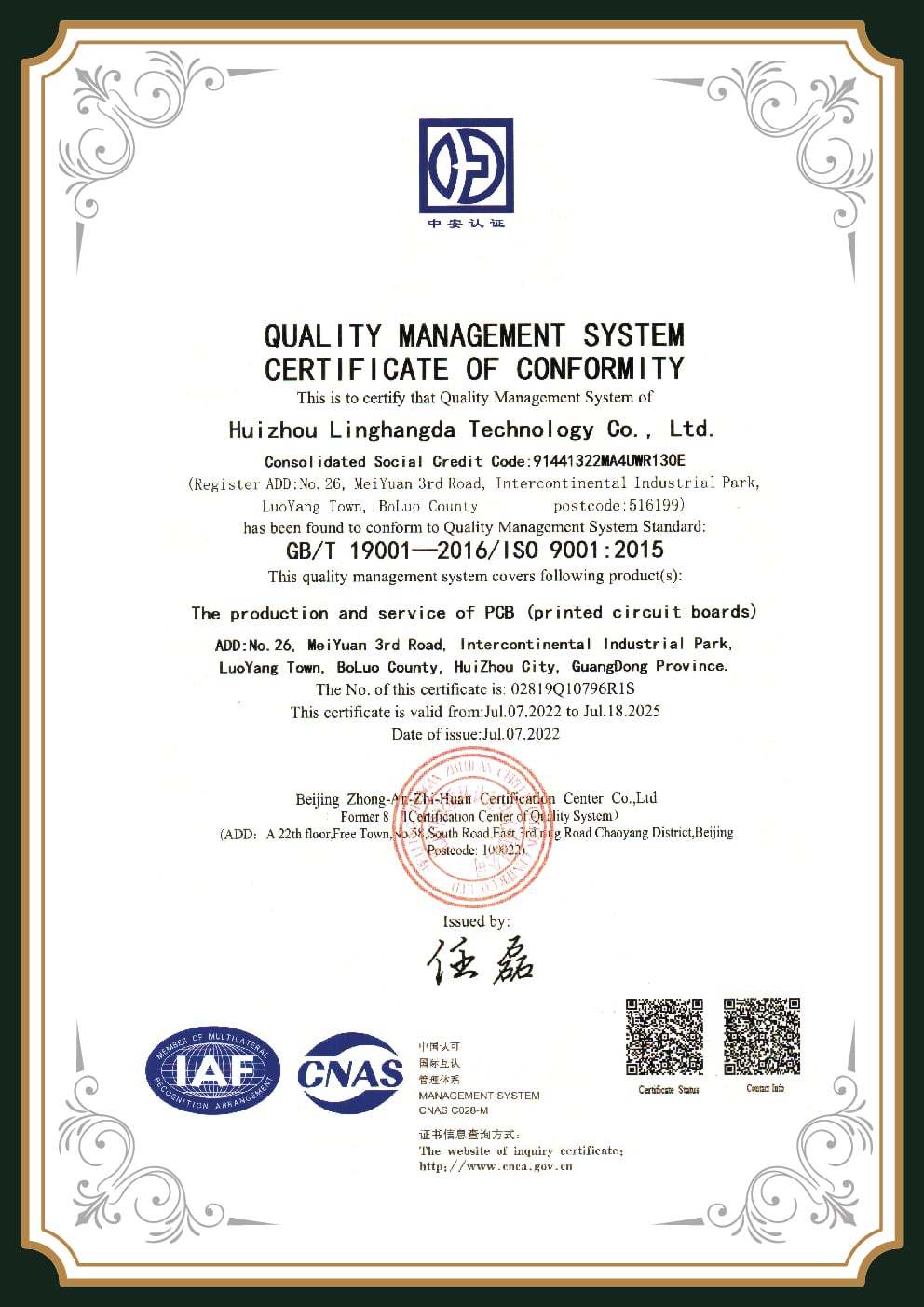
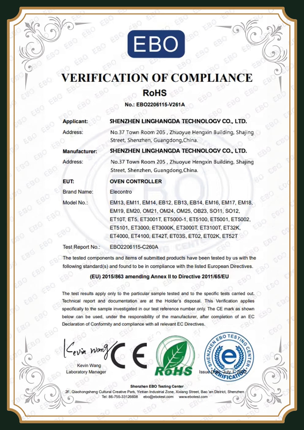
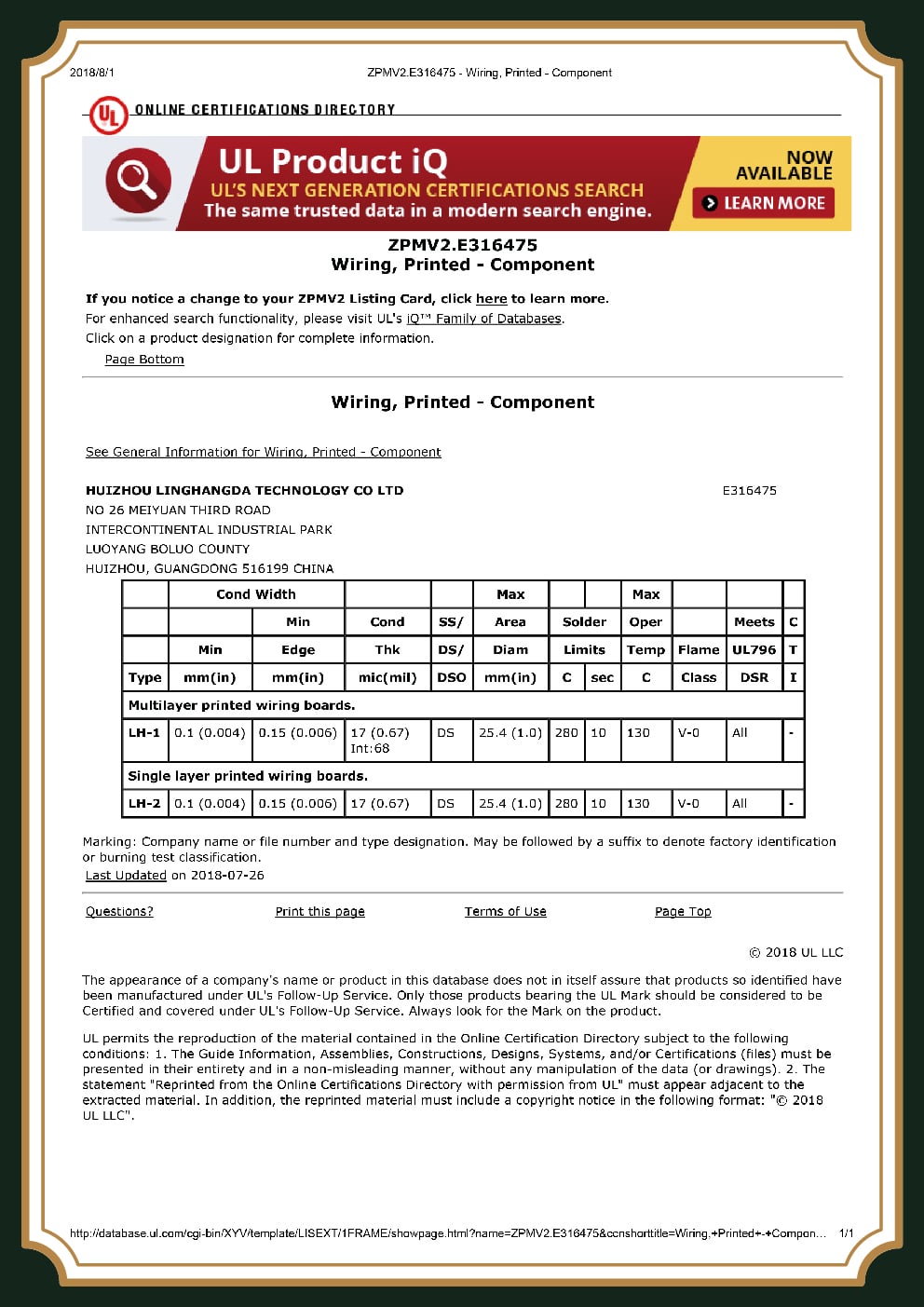
As a high-reliability supplier, certifications are not a logo wall – they’re the audited systems that make Class 3 repeatable instead of accidental. Here’s what each one actually controls.
Procurement Guide — What Actually Drives Your CCA Price & Lead Time
For all but the best CCA suppliers (and a few industry titans may be guilty here, too), pricing isn’t calculated logically: you get a opaque number with no idea why it went up. We believe quite the opposite-because our partners consistently report that they trust and favor working with suppliers that build pricing from their parts, assemble with clarity, and deliver transparency. Thus, we present – with the doors flung wide – the factors that move a circuit card assembly quote, and how they are managed:
01
Build class
Class 3 acceptance and the inspection depth behind it (X-ray, microscopic) cost more per board than Class 2 — and are non-negotiable for defense/aerospace. Specify the class you actually need, not the highest available.
02
Board complexity
Layer count, HDI/rigid-flex construction, fine-pitch BGA density, and mixed SMT/through-hole all raise process steps and yield risk.
03
Component sourcing
Turnkey (we source) vs. consigned (you supply), franchised-distributor traceability, and long-lead or allocated parts are usually the largest and most volatile line on a hi-rel quote.
04
Test & coating scope
ICT fixture development, functional test, conformal coating, and environmental screening add tooling and per-unit cost — and prevent far costlier field escapes.
05
Volume & cadence
Prototype, low-volume, and series production carry different setup-amortization. Stable forecasts and consolidated releases lower unit cost.
06
Documentation & compliance
First-article inspection reports, full traceability records, and ITAR-controlled handling are scoped per program.
Controlling lead time
On hi-rel projects, by far the greatest determinant of lead time has nothing to do with assembly, but component availability and the readiness of a completed test fixture. Programs delivered on-time are those that submit the BOM for early source verification, locking long lead time parts before they are ever needed, and certainly before they’re found to be unavailable upon kitting. Submit your BOM with your RFQ and let us get started on sourcing before any potential shortage arises.
Every estimate is derived from your unique specification: your gerbers, BOM, desired build class, required testing, and volume requirements. Let us see your specification for a transparent, itemized price; you’ll find it built from a direct, top-line comparison of parts, assembly, testing, and the accompanying paperwork.
/// ENGINEERING RESOURCES
Circuit Card Assembly Toolset
Evaluate build classes, map cost drivers, and configure test coverage with our interactive procurement and engineering tools.
01
IPC Build Class Selector
Find the exact IPC-A-610 / J-STD-001 class your CCA requires based on operating environment and failure consequences.
Launch Tool
02
CCA Cost-Driver Estimator
Map the relative cost impact of layer count, volume, sourcing strategy, and test depth on your assembly quote.
Launch Tool
03
Cost-of-Failure Calculator
Calculate the exponential “rule of ten” cost impact of defects escaping from board test to system integration or the field.
Launch Tool
04
Test & Inspection Coverage Recommender
Generate a recommended inspection and test stack based on your board’s density and operating profile.
Launch Tool
Frequently Asked Questions
What is a circuit card assembly (CCA), and how is it different from a PCB or PWB?
A printed circuit board (PCB, also called a PWB or printed wiring board) is the bare, unpopulated board. A circuit card assembly is that board after all electronic components have been soldered on and the assembly has been tested — what many engineers also call a PCBA. “CCA” is the term used most in defense and aerospace documentation; functionally, CCA and PCBA describe the same finished, populated assembly.
What is IPC Class 3, and why does it matter for defense electronics?
IPC defines three product classes. Class 3 is the high-reliability tier for hardware where continued performance is required and failure is not an option — defense, aerospace, and life-support. Compared with Class 2, Class 3 demands 100% side-fillet wetting (vs. 75%), zero plating voids, thicker through-hole copper, tighter annular-ring rules, and 100% microscopic inspection. Those criteria are what let an assembly survive thermal cycling and vibration in the field.
Is PCBark AS9100 and ITAR compliant — can you handle controlled defense work?
PCBark operates an AS9100 aerospace quality system, is ITAR registered, and builds to IPC J-STD-001 and IPC-A-610 Class 3. To be transparent: ITAR-controlled technical data carries U.S. jurisdictional handling requirements, and the right manufacturing footprint depends on your program’s specific control classification. We are best matched to high-reliability aerospace, industrial, and export-eligible defense-adjacent programs — and we will tell you directly, up front, if a controlled requirement is better served elsewhere rather than put your compliance at risk.
What testing and inspection is included on a high-reliability CCA?
Our standard high-reliability flow includes solder-paste inspection (SPI), automated optical inspection (AOI), X-ray for BGA and hidden joints, in-circuit test (ICT), and functional test, with conformal coating and environmental screening (thermal cycling, vibration) added per the program’s requirements. Full lot traceability runs from component sourcing through final electrical test, and for coated assemblies we record coating thickness and adhesion so the documentation package matches what was actually built and shipped.
What happens if a board has a problem after delivery?
Single-thread accountability is the reason we keep fabrication, assembly, and test under one quality system: when a board needs a root-cause answer, there is no gap between a fab house and a separate assembler to fall into. We provide failure analysis, corrective action, and rework or replacement under our quality terms — the opposite of the “won’t fix it” experience that drives buyers away from the lowest-cost assemblers.
Can you handle low-volume and mixed-technology (SMT + through-hole) builds?
Yes — high-mix, low-to-medium-volume builds are our core, with SMT, through-hole, and rigid-flex on a single assembly.
How long does a prototype CCA take versus production?
Prototype and quick-turn builds move faster than qualified production, but on high-reliability work the schedule is usually set by component availability and test-fixture readiness rather than assembly time. Send your BOM with your RFQ and we will give you a realistic, lead-time-critical-aware estimate rather than an optimistic one that slips.
Build your next CCA where Class 3 is the default, not an upgrade
Send over your gerbers, BOM, and build specifications to receive a DFM review and a clear, detailed estimate including price points for parts, labor, testing, and all documentation.
![16-24 Layer PCB: Stackup, Lamination & Design Guide [2026]](https://pcbark.com/wp-content/uploads/2026/07/16-24-layer-pcb-guide-featured-2-150x150.png)


