Get in touch with PCBark Company


Quick Specs
| Substrate | Polyimide (PI), 12.5-125 µm, Tg generally 250-300°C |
| Copper foil | Rolled-annealed (RA), ½-1 oz typical |
| Reflow peak | Sub-235°C, slow ramp (≤2°C/sec) |
| Governing standards | IPC-2223 (design), IPC-6013 (board qualification), J-STD-001 (soldering), IPC-A-610 (assembly acceptance) |
| Inspection stack | AOI, X-ray, flying probe or ICT, functional test |
| Pre-bake | Typically 120-125°C, 4-8 hours (moisture removal before reflow) |
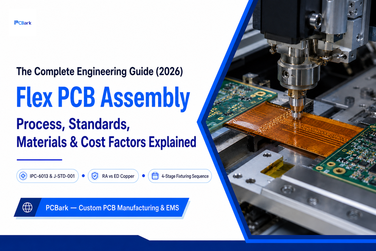
flex pcb assembly refers to the direct mounting, soldering and test of electronic components to a flexible polyimide substrate, and it has very little similarity to the assembly process of rigid FR4 boards. Due to the fact that the substrate itself is flexible and hygroscopic, the whole procedure starting from the paste printing until the final reflow step has to overcome some inherent limitations caused by the material’s inherent tendency to warp, crinkle or blister when in normal SMT environment.
A flex pcb assembly (FPCA) attaching process places the components on a pliable polyimide substrate supported on a hard fixture with a reflow temperature profile under 235°C at production volumes, holding the film flat and water-free during soldering.
Key Facts Before You Spec a Build
- Thinner polyimide isn’t always the better bet – while it does have a tighter static-flex radius it doesn’t necessarily mean it will be more reliable in dynamic-flex fatigue.
- IPC-6013 covers the board, (Class 1/2/3), NOT the soldering or assembly processes, this would be J-STD-001, and IPC-A-610.
- The rolled-annealed copper can withstand many bending cycles, because the grain structure has been elongated through rolling; not just because it’s a “softer” type of copper.
- Moisture is the single greatest assembly threat on flex – polyimide has been quietly sipping moisture from normal room air long before reflow ever begins.
- Reliability doesn’t show up in a vendor’s marketing claims – it shows up in their inspection stacks (flying probe, AOI, x-ray).
What Is Flex PCB Assembly?
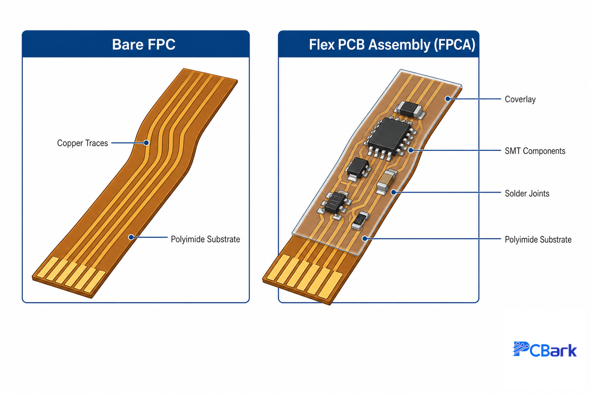
Flex pcb assembly (FPCA) is where solder paste, materials, and coatings are attached to a bare flexible printed circuit (FPC) to create a functional electronic assembly. The bare FPC – a strip of copper etched onto thin polyimide – is simply wiring; the assembly is the completed item. IPC-A-610 governs how that finished assembly gets inspected once it’s done.
That inspection standard (NASA’s own workmanship-standards program adopts this same IPC framework for mission hardware) is one of the reasons the fabrication/assembly scope distinction matters at quote time, not just at final acceptance. It’s a problem PCBark resolves on nearly every intake call: a design file arrives certified to a spec sheet, but nobody has confirmed whether the request is for fabrication, assembly, or both, and that gap is the structural reason so many flex quotes need a second round.
Terms become confusing because the industry applies multiple synonyms to this process: flexible PCBA, flex pcb assembly, flex circuit assembly, FPC SMT assembly, flexible circuit assembly are all ways to refer to mounting parts on flexible substrates of all kinds, be they single-sided, double-sided, multi-layer, or a rigid-flex flex section. You also may wish to differentiate between circuit board assembly and its preceding stage; bare PCB fabrication and flex pcb fabrication etch the flexible circuit material for a flex printed circuit board, and board fabrication for a flex substrate requires different materials than for the assembly step. Both occur under the same roof at many full-service manufacturing solutions shops, though.
A word on production: it might seem that the core process is the same between a prototype build and a production run. However, a prototype build focuses more on the turnaround of the finished PCBs, rather than the lowest possible cost per unit. With a high-volume production run, higher panelization and tooling investment can be afforded per board — on a typical full-service line, that’s the difference between a single-cavity carrier jig for a handful of prototype boards and a multi-cavity panel jig built specifically to keep unit cost down once volumes justify it.
This uncertainty of scope isn’t theoretical, it’s the single most frequent reason that leads to quote disconnects on flex programs. An engineer provide Gerber and a BOM, intending a turnkey “flex pcb assembly” quote. That EMS reads the BOM, expecting to price a bare-fabrication only, because the RFQ was a generic list of “flex PCB parts and materials.” Two weeks and endless email strings later, we realize we never actually quoted the BOM components. By clearly identifying what’s to be included – flex PCB assembly parts, a PCB prototype vs. production run, sourcing, placement and test, not simply the “bare flex board,” you can short-circuit this costly exchange.
What Are the Differences Between PCB and PCBA?
PCB (Flexible Board) Bare board: traces only. PCB assembly (Flex PCB assembly): with solder mask (solder) and components and/or coverlays and tested. If we talk about flex PCB: FPC is the bare flexible board, flex PCBA or FPCA is the assembled FPC. Someone asking for a quote for “flex PCB” instead of “flex PCB assembly” wants a different thing entirely (one is fabrication only, the other one include sourcing, placement, soldering, test, etc).
Screening for Flex vs. Rigid-Flex Assembly
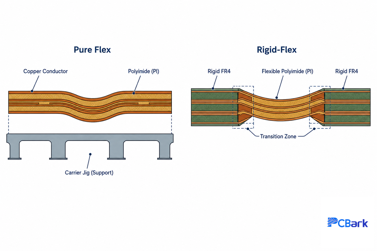
First, take a pause and do a quick check on flex and rigid-flex pcbs – are you sure you want a plain flex and rigid pcb combination, or true rigid-flex boards? Pure flex is all flexible and built with continuous support on a carrier through all stages of the assembly process. Rigid-flex uses integrated rigid and flex parts, which changes the challenge for assembly from keeping it flat to managing differential thermal expansion. Often, on a flex and rigid-flex pcb decision, designers choose rigid-flex (which is significantly more expensive than comparable rigid pcbs and more complicated to fabricate due to the additional lamination cycles) when a standard flex circuit with a stiffener at the needed location would perform equally reliably but for much less tooling cost because “rigid-flex sounds better.” On the shop floor, that mistake is usually caught late: a rigid-flex PCB stackup gets quoted, tooled, and half-fabricated before anyone re-checks whether the design ever actually needed the extra lamination cycles, by which point the tooling spend is already sunk – a structural risk PCBark flags at DFM review specifically because IPC-2223’s own rigid-flex PCB design guidelines assume you’ve already made that call deliberately, not by default. It’s the kind of problem that ISO 9001-certified process discipline at intake is built around catching before tooling, not after. Check PCBark’s flex and rigid-flex assembly capability page for a full breakdown by build type if you want to dig into it (this compares by the numbers the total cost by type) or look at our rigid-flex pcb manufacturing guide for more detail on rigid-flex pcb design and fabrication details, or vet a rigid-flex PCB manufacturer against the same 6-point checklist later in this guide.
Materials & Substrate Selection: The Physics Behind the Spec Sheet
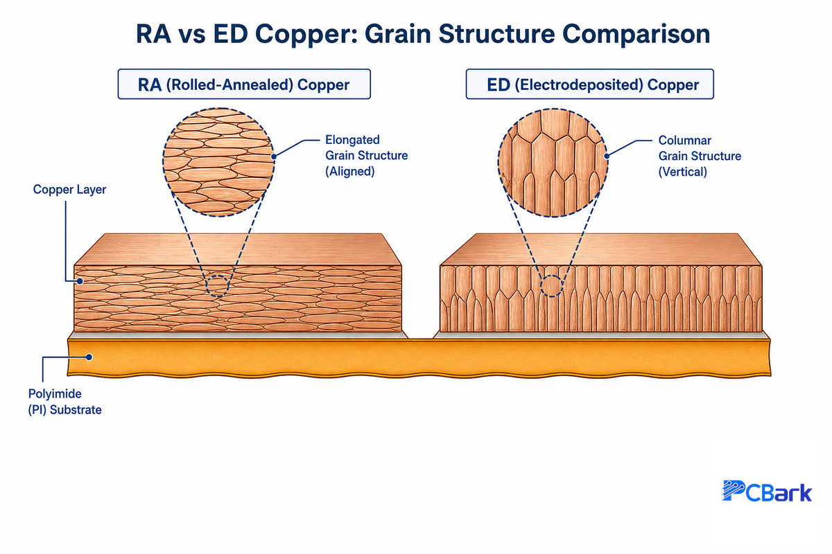
There isn’t much in any flexible pcb assembly datasheet besides a list of few commonly used flex materials (polyimide, rolled annealed copper, coverlay, ENIG), whether the build is single-sided or double-sided. Most resources won’t explain why each material is selected for the application – this “why” is the reason your device survives a bend cycle.
Polyimide: heat-resistant, and quietly thirsty
Polyimide (PI) is a commonly used flexible substrate due to its superior resistance to both the reflow temperatures and repeated bending as compared to more generic polymers. More specifically for flex pcb assembly, the glass transition temperature (Tg) of the polyamide-imide polymer resin (the substrate used for flex PCBs) will affect its performance. When the Tg of the PI material falls below approximately 250°C, the substrate’s ability to withstand heat and remain dimensional stability during the reflow soldering process is compromised. Optimal materials for high-reliability flex assembly generally target Tg values of 280°C-300°C or higher, a threshold documented directly in USPTO patent filings on flexible metal-clad laminate resin formulation.
The aspect engineers coming from rigid-board backgrounds may find most surprising: polyimide is hygroscopic. It pulls moisture out of normal room air and modern low-absorption grades can be manufactured to something around 0.3% moisture absorption (a range consistent with the low-water-uptake polyimide chemistry documented in peer-reviewed materials research) – but even a couple of days in an unprotected room may mean a board is sufficiently saturated to flash into steam during reflow, creating delamination or blistering (the familiar “popcorning” of sensitive rigid-board components -except flexible substrates are a lot more susceptible than fr4). That’s the real reason pre-bake isn’t an optional step, it’s not just some general “dry the part” operation, it’s an opportunity to remove a known, quantifiable failure mode.
Rolled-annealed vs. electrodeposited copper: it’s about grain structure, not softness
Flexible circuits nearly always use rolled-annealed (RA) copper in place of the electrodeposited (ED) copper found on most rigid boards. This isn’t a marketing gimmick, it’s metallurgy. Rolling elongates copper’s grain structure along the rolling direction – a “β-fiber texture,” as materials scientists call it. ED copper tends to have a columnar or equiaxed grain structure. Research specifically characterizing rolled-annealed copper foil for flex circuit has shown elastic-plastic and low-cycle fatigue behavior characteristic of an optimized foil for bending, while other studies on conventional high-chloride ED copper show relatively poor fatigue ductility. The difference between these two families of foils goes beyond the copper, too: factors like the adhesive system, coverlay composite structure, trace width, and copper thickness will all modify the actual fatigue performance, so any competent flexible assembly partner will discuss the entire stack-up and its long-term manufacturability, not just “we use RA copper” on a reliable flex build.
⚠️ The “thinnest material bends best” myth
Among the recurring assembly challenges buyers ask about, this one comes up constantly: it is true that thinner polyimide can achieve a tighter static bend radius. What is not necessarily true is that thinner is more reliable under repeated dynamic flexing. Fatigue life depends not just on the substrate thickness, but on strain amplitude, trace width, copper thickness and how the flex design manages the stress concentration at the trace-pad transitions. While a rule-of-thumb of 10x the substrate thickness might provide an acceptable baseline for design, it’s no substitute for verifying cycle life against the construction itself.
| Material category | Typical spec | Why it matters |
|---|---|---|
| Polyimide (PI) film — base substrate | 12.5-125 µm, Tg 250-300°C | Standard flex base; hygroscopic, needs pre-bake before reflow |
| Liquid Crystal Polymer (LCP) — base substrate | Dk ~3.0-3.2 at 10 GHz | Lower moisture uptake and better high-frequency signal integrity than PI, used above roughly 5 GHz |
| Rolled-annealed (RA) copper — conductor | ½-1 oz, >30% elongation | Elongated grain structure survives thousands of bend cycles |
| Electrodeposited (ED) copper — conductor | ~1 oz, ~10% elongation | Cost-efficient for static (non-flexing) sections only |
| Acrylic-adhesive coverlay | 12.5-50 µm, up to 200°C | Cost-efficient trace protection for standard-reliability builds |
| Adhesiveless coverlay | Same PI film, no bond layer | Best dimensional stability + lowest moisture uptake for high-density or Class 3 builds |
| ENIG surface finish | ~3-8 µin Au over ~120-240 µin Ni | Long shelf life + flat pads for fine-pitch components |
| Immersion silver surface finish | ~5-12 µin Ag | Excellent solderability, lower cost than ENIG, shorter shelf life |
| FR4 stiffener | 0.1-1.6 mm | General-purpose local rigidity under connectors, lowest cost |
| Stainless steel stiffener | 0.1-0.3 mm | Highest mechanical load capacity in the smallest thickness |
A multi-layer (multilayer) flex build (often three to eight layers, sometimes more for specialized medical or modular designs) adds yet another complexity beyond a double-sided flex construction: each additional lamination step brings with it considerations regarding thermal and mechanical stress plus registration, one of the reasons why builds with more layers of flexible assembly will usually aim for a tighter static bend radius than a single-layer construction.
📐 Engineering Note
If you need to maintain controlled impedance on a flexible link, be aware that the flexible dielectric generally offers tighter, more predictable Dk values than glass-reinforced FR4 or other traditional rigid printed circuit materials – a high-performance benefit for high-speed routing on electronic devices, but one that make stack-up review even more important at the pcb design stage.
How Flex PCB Assembly Actually Works, Step by Step
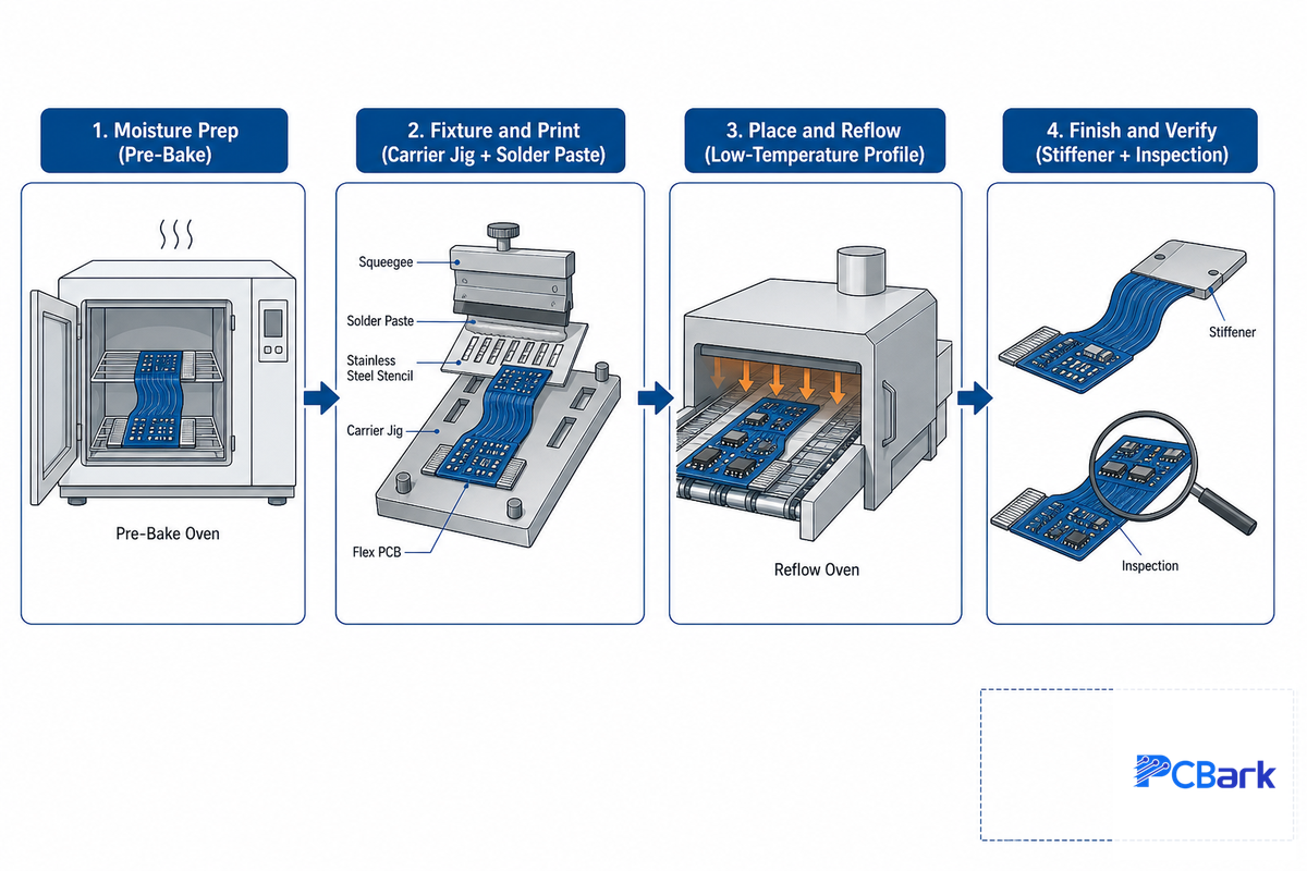
Beyond the marketing hype, flex pcb assembly unfolds in four fairly predictable stages: moisture prep, fixturing, placement and reflow, then finish and verify. What differs from rigid-board SMT is what has to occur at each stage to keep a floppy, sensitive substrate flat, aligned, and undamaged by heat, not just soldered.
4-Stage Flex Fixturing Sequence
Stage 1 — Moisture Prep
Technicians pre-bake the bare flex boards (usually at 120-125°C for several hours, time dependent on board thickness and storage conditions) so the moisture in them won’t flash to steam during reflow.
Stage 2 — Fixture and Print
Technicians insert flex circuit on a rigid pallet or jig-either via pin holes or by vacuum, as it can’t travel on a normal SMT line conveyor alone. Solder paste is then stenciled onto the pads while the board is held down flat.
Stage 3 — Place and Reflow
Pick-and-place machines set the components onto the substrate, carefully controlling the amount of placement force to avoid deforming the very thin board material, then the assembly goes through reflow using a very low-temperature profile (most builds top out below 235°C, well under the 280-300°C Tg ceiling documented for high-reliability polyimide grades) to prevent damage to both the polyimide and the solder joints.
Stage 4 — Finish and Verify
Stiffeners are added post-reflow for localized support where connectors or heavier parts must be installed, the assembly is then released from its jig, and enters the inspection stations-including optical (AOI), X-ray (to check for buried joints) and electrical testing.
Across pcb manufacturing and assembly operations more broadly, for those shop floor operations handling a mixture of flex and rigid parts and their flexible sections, this same four-stage procedure is the primary reason that manufacturing and assembly of a flex board move more slowly through a line than an equivalent rigid board. In the four flex stages above, there’s a fixture-based step and a reflow profile modification that the rigid boards do without-yet, final IPC-A-610 standards inspection must still be met for every part, no matter how much special handling got the assembly there. It’s the structural reason PCBark schedules flex jobs with buffer built into the line plan rather than slotting them in as if they were just another rigid panel.
Why SMT on Flex Substrates Is Genuinely Different
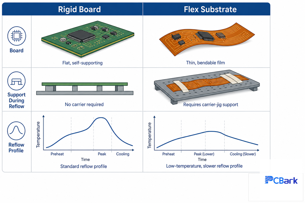
Standard SMT lines are designed to work with rigid boards that can support themselves under solder-paste printing and placement, but flex substrates can’t hold their own shape – and that single difference drives most of the process change a buyer will notice on a flex board quote, from fixturing through thermal profile.
Why Is Continuous External Stabilization (Tooling) a Fundamental Step in Flex PCB Assembly?
Without support from an external carrier or fixture, a pure flex circuit – comprised solely of a very thin and pliant polyimide layer – would flex, sag, or wrinkle and become distorted from the solder printing and component placement process, thereby compromising critical dimensional stability. The need for continuous external stabilization, beginning in the solder stage and extending through component placement and reflow, ensures precise alignment where any misregistration directly results in either an open circuit or a solder bridge.
In terms of thermal characteristics, the significantly lower glass transition temperature (Tg) of polyimide and its relatively lower thermal mass in comparison to the thermal mass of rigid FR4 create another complication. Unlike rigid board processes, which generally use more aggressive profiles, flex parts require extremely shallow and slow temperature ramping and peak during reflow to prevent thermally damaging the polyimide itself (the same Tg ceiling documented in the resin patent literature cited earlier) – in addition to protecting the solder joints from thermal shock. For that reason, specialized low-temperature reflow profiles are employed on the assembly process to handle these flexible boards instead of modifying a standard rigid-board profile.
The failure mode for when a shop misses this process: a batch of flex boards goes on a standard rigid reflow profile because it’s already on the oven, the polyimide near the hot zone will appear discolored or slightly warped, and a post-reflow AOI will pick up lifted pads that wouldn’t have appeared if using a rigid-board profile. It’s a scrap event and its source can be attributed to nothing more than a faulty profile selection-which is why the five minutes it takes to request that vendor produce their documented low-temperature profile is well worth your time instead of relying on the assumption that “we do flex.”
Standards Stack: Which One Answers Which Question
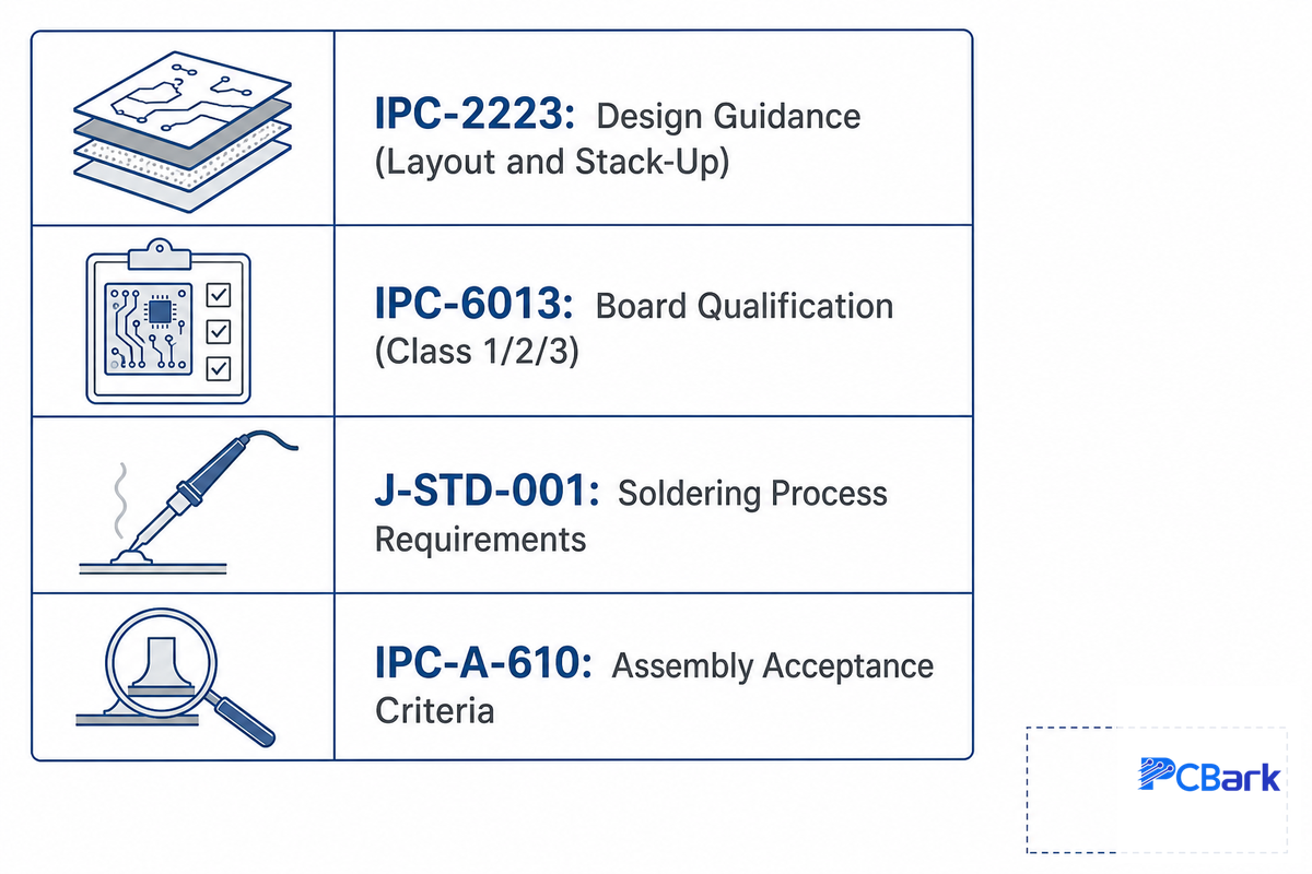
This is where a lot of otherwise perfectly solid technical content takes a dive: IPC-6013 gets routinely referred to as “the” flex assembly standard, but it’s really the board standard, not the assembly profile standard. And understanding the scope matter when writing this into a purchase spec or supplier audit.
| Standard | What it governs | Ask it when… |
|---|---|---|
| IPC-2223 | Flex and rigid-flex sectional design guidance — thickness, bend radius, layout | You’re still in layout and need bend-radius / stack-up guidance |
| IPC-6013 | Board qualification and performance — Class 1/2/3 tiers for the bare/finished board | You need to specify what reliability tier the board must meet |
| J-STD-001 | Soldering process requirements — materials, methods, process control | You’re qualifying the assembler’s soldering process itself |
| IPC-A-610 | Acceptability of electronic assemblies — visual/workmanship inspection criteria | You’re inspecting a finished assembly against a pass/fail standard |
Most of the confusion revolves around the Class system within IPC-6013. Class 1 products need only a basic level of function and the shortest possible lifespan – like simple accessories for consumer electronics. Class 2 devices should have extended reliability – like most industrial or automotive electronics. And finally, Class 3 products are built for the highest levels of reliability and are often designed for extreme environments, where life or death stakes are on the table – aerospace, medical implants, and military-grade equipment. That reliability tier isn’t just a paperwork distinction; it’s the same higher-Tg material grade documented in the polyimide resin patent record discussed under Materials above.
Worked Example: Picking a Class
- Medical implants or any life-sustaining devices → Class 3 (ZERO defect requirement; traceability is expected)
- Industrial sensor or automotive controller → Class 2 (longer reliability but not essential for life)
- Consumer accessories for a relatively short expected lifespan → Class 1 (must work basic functionality but that’s it)
If you’re not sure where your product falls in, have this conversation with the designer before you begin asking for quotes. You don’t want to find this out when your Class 1 board fails in the field during a Class 2 application.
Inspection & Testing: What to Require From Any Vendor
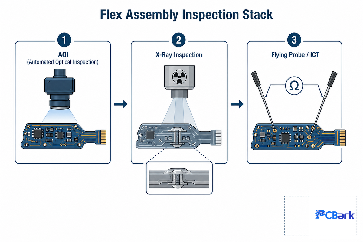
Whichever assembly partner you use, the most reliable indicator of a successful flex board will be the inspection equipment and procedures behind their process. Even NASA’s own workmanship-standards program treats documented inspection procedure, not just the underlying certification, as the real quality signal for interconnection assemblies. Here’s what you need to request, and why it’s important.
- AOI (Automated Optical Inspection) for every assembly: Will identify misalignment, solder bridging, and any other obvious visual issues after reflow.
- X-ray inspection for joint integrity: Any joints that are hidden beneath component bodies or stiffeners and aren’t accessible for optical inspection.
- Flying probe testing or ICT: to ensure that the joints and plated through holes connecting layers of circuitry aren’t just aesthetically acceptable but are also actually electrically conductive.
- Documented pre-bake procedures: You need to know their specific pre-bake temperatures and durations, and if they tailor these to board thickness.
- Bend-cycle test evidence for dynamic applications: a vendor must be able to show that they’ve done rigorous testing to confirm the durability and reliability of the flex design, not just claim they’ve done it.
That last item is not a formality. A documented medical-imaging rigid-flex case (PICA Manufacturing Solutions) shows why: the target was 2 million bend cycles on a 14-layer impedance-controlled build, roughly 700x the 2,000-3,000 cycles a typical flex interconnect tolerates. Its first prototype survived only 10,000 cycles before defects appeared. The fix wasn’t a different material – it was relocating the copper to the neutral bend axis and adding a shielding film to preserve impedance control at the reduced flex-region thickness. That is the kind of iteration a bend-cycle-test requirement is supposed to catch before it becomes a field failure.
What Are the Most Common Assembly Defects Seen in Flexible PCBs, and How Can They Be Prevented?
The most common flex-specific failures fall into three areas: moisture-induced delamination and pad lift, trace cracks at bend areas, and cold or non-wet solder joints from an over-aggressive thermal profile. Delamination traces to polyimide absorbing moisture that flashes to steam during reflow; pre-baking the board removes it before that can happen.
Absorption into the polyimide during the exposure window between fabrication and assembly is the major contributing factor here. Polyimide has much greater water absorption properties than rigid FR4, so exposure of the unassembled bare board to ambient air for an extended time is a root cause for these failures. Trace cracks usually occur at the bend transition rather than directly under the coverlay; extending the coverlay coverage beyond the bend line will improve reliability, and using a round trace-to-pad connection will extend cycle life over sharp right-angled trace transitions. Cold or non-wetting joints typically indicate a reflow profile that wasn’t low enough to prevent an over-temp excursion given the polyimide’s particular thermal limits.
How Do Environmental Conditions Affect the Long-Term Reliability of Flexible PCBs?
Moisture, temperature excursions, and dust/contamination are the three major factors that affect long-term reliability of a flex assembly, and they can interact. Repeated exposure to high humidity will, over time, degrade adhesive bonds even on a build that met specification at shipment.
For a higher-risk environment (automotive underhood, external applications, and some medical applications with sterilization cycles) standard recommendations are a conformal coating, higher-Tg polyimide material selection, and storing boards in a controlled environment between fabrication and final integration into the overall product. Controlling particulate matter and chemical contaminants at the manufacturing stage will further minimize latent defects surfacing in the field.
Where Flex PCB Assembly Is Used
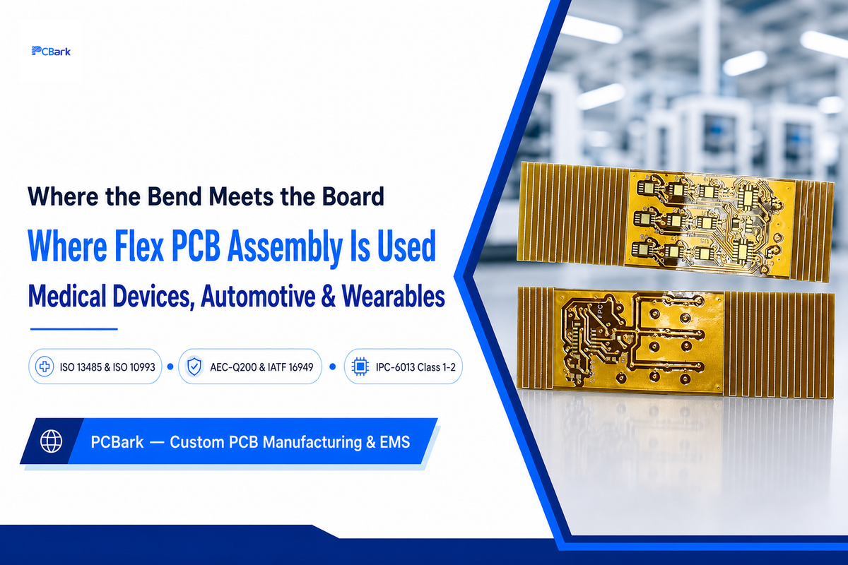
Three key industries drive demand for flex pcb assembly, and each one prioritizes a different attribute above the rest: medical devices demand biocompatibility and zero-defect traceability, automotive demands thermal range and vibration durability, and wearables demand dynamic bend-cycle life in an increasingly miniaturized footprint.
| Industry | Governing standards | Top priority |
|---|---|---|
| Medical devices (implantable, wearable monitors) | ISO 13485, ISO 10993 (biocompatibility), often IPC-6013 Class 3 | Biocompatibility + zero-defect traceability |
| Automotive (EV, ADAS) | AEC-Q200 (component stress qualification), IATF 16949 (quality system) | Thermal range (typically -40°C to +150°C) + vibration durability |
| Wearables & consumer electronics | Typically IPC-6013 Class 1-2 | Dynamic bend-cycle life + miniaturization |
On the medical side, one additional point to remember. As the table above summarizes, ISO 13485 describes a Manufacturer’s quality management system, whereas ISO 10993 biological requirements generally govern biocompatibility testing on a device where the flex is intended to contact the patient. Implantable medical devices require that not only the base material be acceptable, but the specific grade, surface finish and any post fabrication treatments also be cleared through the bio-evaluation process — exactly the constraint documented in USPTO patent filings on flexible implantable electrode-array construction, where the flex substrate, package material, and electrode design all had to clear biocompatibility together, not as separate approvals. While polyimide has been accepted in medical applications for some time due to its good biocompatibility history, it’s still the specific grade and surface treatment that requires the bio-clearance. On the automotive side, the AEC-Q200 qualification describes the component’s level of stress tolerance and the IATF 16949 standard addresses the manufacturer’s quality management system; neither qualifies a finished flex assembly in and of itself. A good automotive grade flex assembly supplier should be prepared to demonstrate how they approach both areas and ensure their reliability test stack is compatible with your other automotive component PCB requirements.
What Drives Flex PCB Assembly Cost

Flex assembly is inherently more expensive than its rigid counterpart. Polyimide laminate is generally multiple times the cost of FR4, plus the cost associated with the jigs to flatten unique designs for routing. Adding layers beyond two, plus the choice of stiffener and surface finish, stack more cost on top of that.
The costliest mistake we’ve observed in flex pcb assembly quotes isn’t the material – it’s the mismatch between the required reliability Class and the actual application. In cases we’ve reviewed, consumer-wearable device specs called out for IPC-6013 Class 3 inspection/documentation have added roughly 20-40% to unit costs with testing and tooling the application never needed, whereas a flex PCB assembly manufacturer quoting the same product for the correct Class can come in tens of percent lower, without a material change. Before quotes, not after, review the Class – it’s the single highest-impact cost-driver on a flex program. Instead of re-listing it, the detailed, quantified version – including the exact cost driver weights for your build – is located at PCBark’s flex PCB assembly page. The cost-driver tool there will help you see exactly where your project dollars will be concentrated before you request a quote.
How to Evaluate a Flex Assembly Partner

Not every PCB assembler that advertises “flex” actually performs flex PCB production with a flex-dedicated process – some simply run a rigid-board line more carefully and call it flex-capable. Here’s a vendor-agnostic checklist worth working through before selecting one, regardless of what any single certification claims.
6-Point Flex Assembly Partner Check
- Documented low-temperature reflow profile -not just a generic rigid-board profile used “carefully”
- On-hand inventory of polyimide and adhesiveless laminates – your build shouldn’t wait on specialized material procured on-demand
- Dedicated rigid carrier tooling – tailored for your design, not a one-size-fits-all pallet
- Full inspection stack – including AOI, X-ray and either a flying probe or ICT, not just visual inspection (the same layered-inspection principle NASA’s workmanship program applies to mission-critical interconnects)
- fabrication and assembly – located in the same facility (or with a tightly integrated, well-defined process) -to minimize the blame game over stiffener or coverlay issues
- Real lead times – ask what drives the timeline (layer count, stiffener strategy, finish, testing requirements) and tie a firm delivery date to your files, rather than accepting marketing figures.
“The vetting conversation we wish more buyers had earlier is about the standards stack, not just the certificate wall. A supplier can hold ISO 9001 and still not have a documented low-temperature reflow profile for polyimide. Ask for the profile, not just the certification.”
If your assessment leans toward a full-service flex and rigid-flex, you can drill down into PCBark’s flex pcb manufacturer capability page for the same detailed checklist of fabrication-side capabilities.
Industry Outlook: What’s Changing in Flex PCB Assembly
In the standards space, near-term changes are the most tangible. Industry discussions on updates to IPC-2223 and IPC-6013 are currently focused on bridging reliability gaps in the Class 3 context, so buyers sourcing medical or aerospace-level flex PCBs for procurement in the next cycle should expect higher documentation and testing expectations, not lower. If you’re already defining a Class 3 project scheduled for completion in 2026-2027, build in schedule buffer to accommodate a potential mid-project standards revision. Material science hasn’t stood still while the standards catch up, either: newer patent filings on low-dielectric polyimide film show the substrate chemistry itself is still an active area of investment, not a mature, static commodity.
Also, the structure by which people are actually getting to the technical answers in the first place has changed: in the process of research for this guide, the AI Overview generated by Google for “flex pcb assembly” sourced almost all its references from long-form technical guide content (not product or service pages) – a personal observation from the search landscape research that informed this guide, not some third-party report. In practice, this means that the assemblers and fabricators producing technical, standards-literate content are the ones that will get picked up by engineers seeking answers from AI tools, not necessarily by engineers searching for answers in a web browser directly.
Demand Side Miniaturization in Wearables and Medical devices are continually increasing assembly precision requirements-finer pitch components and higher placement accuracy, for example. However, exact market size estimates vary depending on the source, and thus they aren’t worth focusing on too carefully; the growth in the Medical and automotive flex market size is a much more consistent trend than any single size estimate.
Frequently Asked Questions About Flex PCB Assembly
Q: What is rigid-flex?
View Answer
A rigid-flex is a circuit where permanent FR4 sections integrate with flexible polyimide sections into one substrate, joined by continuous copper layers instead of separate boards linked by cables. It folds a design into a tight 3D shape or eliminates wiring harnesses, at a cost premium over either pure flex or pure rigid boards.
Q: What is a flex PCB?
View Answer
A flex pcb (flexible printed circuit board) is a flexible electronic circuit fabricated on polyimide instead of the more common FR4 (rigid fiberglass epoxy). It can be built in one, two, or more copper layers, designed to fold, bend, or flex repeatedly – eliminating cable assemblies or fitting into a curved enclosure.
Q: Why isn’t flex PCB assembly handled the same way as rigid-flex PCB assembly?
View Answer
Pure flex assembly’s core challenge is maintaining dimensional flatness, solved with continuous carrier-jig support at each step. Rigid-flex assembly’s challenge differs: the FR4 and flex zones expand at different rates under heat, so controlling process temperature and managing mechanical stress at the interface region becomes essential to avoid delamination or board failure right at the transition zone, where the mismatch is worst.
Q: What factors should be considered when selecting materials for a flex PCB assembly project?
View Answer
Four factors matter most: base film type (polyimide for high-temperature stability; cheaper low-temperature films for less-demanding builds); copper type (rolled-annealed for any bending application, for fatigue life; electrodeposited only for static sections); adhesive system (adhesiveless laminate for best stability at a premium; acrylic for lower cost); and surface finish (ENIG or immersion silver for solderability). Getting any one of these wrong rarely fails immediately – it surfaces months later as a bend-cycle fatigue crack or a delaminated pad.
Q: What’s the main difference in assembly difficulty between a flex PCB and a rigid-flex PCB?
View Answer
Flex assembly’s core requirement is continuous fixturing to keep an unsupported substrate flat and aligned through every process step. Rigid-flex assembly’s core requirement is closer thermal-profile control across the FR4-flex transition, where the two materials expand at different rates under heat.
Q: Why not make every circuit board flexible?
View Answer
Cost and complexity. Flex laminate costs more to fabricate than FR4, requires custom carrier tooling, and has a tighter reflow tolerance, so yield runs lower than an equivalent rigid build. If a design has no need for bending, folding, or saving space, rigid FR4 is the more economical choice; flex earns its keep only when those advantages outweigh the added cost. That calculation belongs in a DFM conversation before tooling starts, not after the money is spent.
Why We Write This
PCBark wrote this flex pcb assembly guide largely in response to the proliferation of marketing-oriented and/or incorrectly scoped assembly information online – including, we’ll admit, an early draft of our own outline that briefly mis-scoped IPC-6013 as an assembly standard rather than the board-qualification standard it actually is. We caught and corrected it before publishing, and we’re noting it here because getting standards scope right matters more than getting it published fast. Reviewed by the PCBark technical team.
References & Sources
- IPC-6013: Qualification and Performance Specification for Flexible/Rigid-Flexible Printed BoardsGlobalSpec Standards
- U.S. Patent 7,364,799, Polyamide-imide resin, flexible metal-clad laminate, and flexible printed wiring boardUSPTO
- U.S. Patent 7,728,102, Polyamide-imide resin, flexible metal-clad laminate, and flexible printed wiring boardUSPTO
- Poly(ester imide)s with Low Linear Coefficients of Thermal Expansion and Low Water UptakePMC, National Institutes of Health
- Mechanical Properties and Microstructure of Rolled and Electrodeposited Thin Copper FoilRare Metals (Wiley)
- International Automotive Task Force, IATF 16949 OversightIATF
- AEC-Q200: Stress Test Qualification for Passive ComponentsAutomotive Electronics Council
- All About Flex: Flex Circuit Specifications for Commercial and Military ApplicationsI-Connect007
- Case Study: Innovating Medical Healthcare Technology with Rigid Flex PCB DesignPICA Manufacturing Solutions
- Workmanship Standards for Printed Wiring AssembliesNASA Safety and Mission Assurance
- U.S. Patent 7,447,551, Flexible Implantable Electrical Stimulator ArrayUSPTO
- U.S. Patent 12,497,487, Low-Dielectric Polyimide Film and Method for Producing SameUSPTO
Related Articles
- Flex PCB Assembly, capability matrix, cost-driver tool, and RFQthe commercial/procurement companion to this guide
- Flexible PCB Manufacturer: What to Know Before You Sourcecopper ductility and vendor-vetting deep dive
- Rigid-Flex PCB Manufacturing: Build Envelope and Bend-Radius Rulesfor designs that need permanent rigid sections
- Automotive PCB: IATF 16949 and AEC-Q Design Requirementsfor underhood and ADAS applications