Get in touch with PCBark Company

Why Heat Destroys Electronics, and How Aluminum PCBs Fix It
What a aluminum pcb really is…
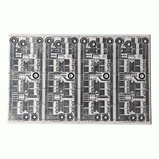
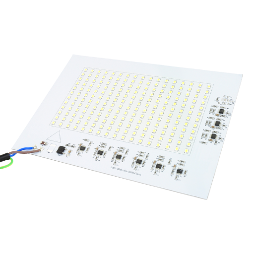
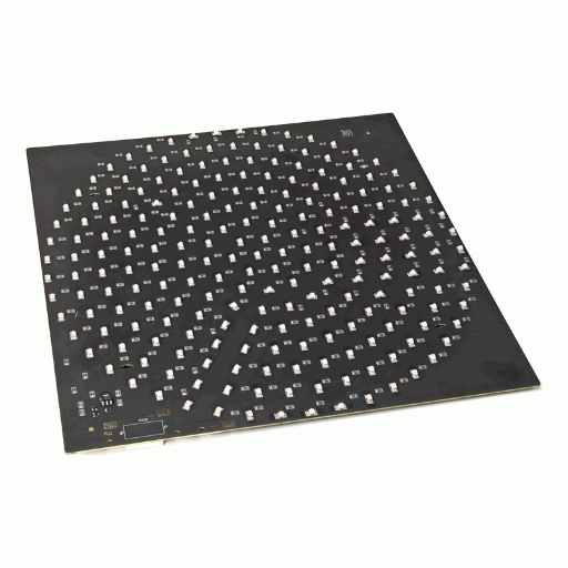
An aluminum pcb is a printed circuit board on metal-typically aluminum, sometimes copper- bonded to the copper circuit layer through a thin thermally conductive dielectric. And for only one reason. Any watt a component dissipates has to get out of the board before its junction temperature gets past maximum. It can’t on a standard FR-4. (background: IEEE thermal-management literature)
This is where many designs fail.
A 3 W power LED or MOSFET driver rests on FR-4, with its laminate dissipating heat at about 0.25 W/mK. There’s no place for heat to get out, so it back into the die. This raises its temperature, reducing output current, light level and lifetime-as do all electrolytic and semiconductor lifespans and voltages. Teams fight heat rise with heat sinks, fans, and thermal vias-more complexity, weight and opportunity for failure.
The four layers that make heat dissipation work
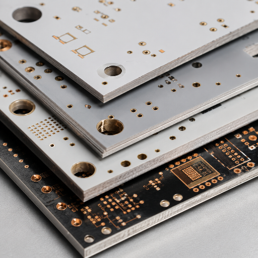
What lets an aluminum circuit board move the heat that an FR4 board traps comes down to its layer stack. Unlike a conventional printed circuit board built on woven glass, an aluminum PCB is a four-layer sandwich, and each layer has one job in the heat path:
01
Copper foil circuit layer
the patterned copper foil that carries your circuit, typically 1–6 oz. Copper thickness here sets current capacity, exactly as on any printed circuit board.
02
Thermally conductive dielectric (insulation) layer
a thin ceramic-filled polymer that provides electrical insulation while still conducting heat downward at 1.0–5.0 W/m·K. This is the layer that separates a good metal core board from a mediocre one.
03
Aluminum base (substrate) layer
the aluminum substrate, usually a 5052 or 6061 alloy, that acts as an integrated heat spreader and the structural base material of the board.
04
Backing / finish
surface treatment and optional base finish that protect the aluminum substrate during assembly and service.
PCBark Aluminum & Metal Core PCB Capabilities (Standard → Maximum)
Most manufacturer pages give you one column of “typical” specs for an aluminum circuit board, so you never know whether your edge-case design is in range. We publish three. The 3-Tier Aluminum PCB Capability Matrix below shows our standard production window, our best-capability window for demanding heat dissipation jobs, and the absolute maximum we have qualified, so an engineer can match a printed circuit board to the right tier before sending a single Gerber file.
DFM CHECK // PASSED
Most of that table is filled with, frankly, hype – except for two numbers. The maximum dielectric conductivity of 5.0 W/mK at the top edge of what production thermal-clad laminates achieve. Independent IMS dielectric patent applications, including U.S. Patent No. 9,551,082 B2, reveal ceramic dielectric layers over 5 WmK and dielectric strength greater than 50 kVmm, so you know it’s a hard material limit and not marketing speak. The maximum of 6-layer makes a huge difference because most aluminum-PCB shops don’t go beyond one or two layers; with multilayer metal core you’ll be able to lay out the entire power and control logic on a single board managed with thermal. (dielectric ceiling verified against USPTO US 9,551,082 B2)
| Parameter | Standard Capability | Best Capability | Maximum Capability |
|---|---|---|---|
| Product type | Single- & double-sided aluminum PCB | High-conductivity, LED & power aluminum PCB | Multilayer aluminum, copper base, metal core hybrid |
| Layers | 1–2 | 1–4 | 6 |
| Board thickness | 1.0–2.0 mm | 0.8–3.0 mm | 0.6–5.0 mm |
| Aluminum base thickness | 0.8–1.5 mm | 0.6–3.0 mm | 5.0 mm |
| Copper weight | 1–2 oz | 1–4 oz | 6 oz |
| Thermal conductivity | 1.0–2.0 W/m·K | 2.0–3.0 W/m·K | 5.0 W/m·K |
| Min trace / spacing | 0.15 / 0.15 mm | 0.10 / 0.10 mm | 0.075 / 0.075 mm |
| Min hole size | 0.30 mm | 0.20 mm | 0.15 mm |
| Hole copper thickness | ≥20 µm | ≥25 µm | ≥35 µm |
| Surface finish | HASL-LF, OSP, ENIG | ENIG, HASL-LF, OSP | ENIG, Immersion Silver, Immersion Tin |
| Solder mask | White, black, green | White, black, matte black, blue | Customized colors |
| Profiling | CNC routing, V-cut | CNC, V-cut, punching | Irregular & complex profiles |
| Max board size | 400 × 500 mm (up to 1500 × 400) | 500 × 600 mm | 600 × 1200 mm |
| Withstand voltage | 1–2 KV | 2–4 KV | 6 KV |
| Applications | LED lighting, power modules | Automotive lighting, industrial control, power electronics | High-power thermal modules, new energy equipment |
Aluminum PCB vs FR-4 vs Copper Core, Performance Comparison
The counter-intuitive part: a higher base-metal conductivity does not automatically mean a cooler board.
Copper conducts at ~386 W/m·K and aluminum at 138–167 W/m·K, but the real thermal bottleneck is the thin dielectric layer between the copper circuit and the metal base, it runs only 1–8 W/m·K and dominates total thermal resistance. Choosing a board by base-metal alone is the most common mistake we see in incoming designs.
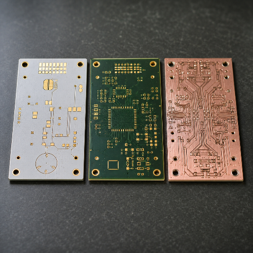
Which explains why you’re comparing the merits of each total stack in terms of thermal resistance at your component-to-heatsink junction and not solely aluminum versus copper. As the Aluminum vs FR-4 vs Copper-Core 8-Metric Comparison below indicates, this comparison utilizes recorded as well as published data values, and no mere High/Medium/Low designations. (metal-core dielectric basis: USPTO US 9,265,160 B2)
| Metric | FR-4 (standard) | Aluminum MCPCB | Copper-Core MCPCB |
|---|---|---|---|
| Laminate / dielectric conductivity | 0.25 W/m·K | 1.0–5.0 W/m·K (dielectric) | 1.0–5.0 W/m·K (dielectric) |
| Metal base conductivity | — | 138–167 W/m·K (5052 / 6061) | ~386 W/m·K (C110) |
| Thermal resistance RθJA (TI LED test) | 61.56 °C/W | 39.1 °C/W | lower still |
| Heat transfer vs FR-4 | 1× baseline | ~8–9× faster | highest |
| Relative bare-board cost | 1× | 2–4× | 4–8× |
| Base temperature tolerance | Tg 130–140 °C | up to ~400 °C | up to ~400 °C |
| Layer flexibility | 1–20+ (multilayer) | 1–6 layers | 1–2 typical |
| Best fit | general logic / signal | LED, power, automotive thermal | extreme high-power, RF |
Engineering Note, reading the table
For most signal and logic boards, FR-4 will be your workhorse.
For situations when only a component heat will do for limited junction temperature – and nothing more – metal core costs 2- to 4 times as much but merits its price, for example, in LED and power applications when thevezane gap, otherwise not bridged with copper at least within the reasonable cost ranges of 2.0-3.0 W/mK for the dielectric in an aluminum MCPCB, and copper core as an aluminum with its still-on-the-board-for-what it’sworth heat would be restricted to exceedingly extreme usage cases like RF power Amplifiers with excessive current density.
8–9×
faster heat transfer than an equivalent FR-4 board, which in high-power LED designs has let teams drop bolt-on heatsinks and report assembly-cost reductions reported up to 58% in published industry cases.
Source: heat-transfer ratio per SF Circuits / Power Electronics News; cost case per SMT Magazine (Saturn Electronics, 2012). Figures are industry references, not a PCBark guarantee.
Board Types & Selection: Single/Double-Sided, Multilayer, Copper Core & IMS
The correct metal core board is one that meets your heat load, layer count and cost target-getting either wrong cuts both ways: Over specifying a copper core PCB for a simple LED string costs 4-8 times the board expense for no added benefit, while under-specifying might cost you dearly, throwing you back into the die and stressing your component until early failure.
That trade-off exists because the dielectric conductivity and copper thickness need to match the watts that you’re dissipating-not whatever the label says.
Since we build all five below at our one in-house single-sided to 6-layer multilayer line, selection is entirely a specs decision, not a hunt to find just anyone with any type of board on hand. Unlike fab-only sources that may push you toward what they stock, at PCBark, we’ll rate the fit during DFM review.
Follow the 5-Signal Metal-Core PCB Selection Path:
heat load, layer/routing density, operating environment, production volume, and cost target
Our Selection Matrix
Our selection matrix below will show you where each board type – up to the very edge (both the metal-core and the hybrid metal-clad PCB boards) – fits best.
| Board type | Layers | Dielectric cond. | Best for |
|---|---|---|---|
| Single-sided aluminum | 1 | 1.0–2.0 W/m·K | LED strips, bulbs, low-cost lighting |
| Double-sided aluminum | 2 | 2.0–3.0 W/m·K | Power modules, denser LED arrays |
| Multilayer aluminum | up to 6 | up to 5.0 W/m·K | Combined power + control electronics |
| Copper-core MCPCB | 1–2 | dielectric + ~386 W/m·K base | Extreme high-power, RF amplifiers |
| IMS (insulated metal substrate) | 1–2 | 1–5 W/m·K | Automotive, high-reliability drivers |
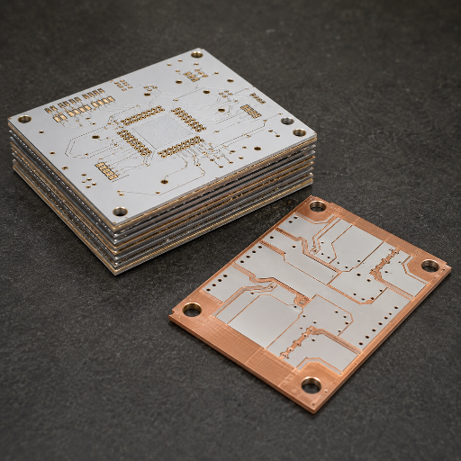
Single- & double-sided aluminum PCB
The single-sided metal core. The workhorse for LED lighting. A single layer of copper placed over our aluminum dielectric and base pulls the heat down from the LEDs where it can spread into the copper and dissipate through the board. Add a second layer to the backside for the power components and you double up the routing for higher interconnect requirements without veering from the metal-core thermal path.
1–2 layers · 1.0–3.0 W/m·K · 1–4 oz Cu · MOQ-flexible from prototype
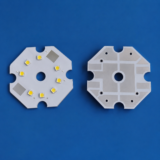
Multilayer & copper-base / hybrid metal core
The multi-layer metal core. Designed for up to 6 conductive layers on a single board, allowing you to lay out control logic and other components on the same thermally managed metal core. Available as full-copper and hybrid metal-cores in an ever-expanding portfolio that maximizes heat transfer, allowing the ultimate in RF power designs and high-current applications components, with maximum-tier 5.0W/mK dielectric and up to 6oz copper layer construction.
up to 6 layers · up to 5.0 W/m·K · up to 6 oz Cu · 600 × 1200 mm max
Applications: LED Lighting, Automotive, Power Electronics & New Energy
The metal core, aluminum and metal core pcb layered construction. These boards become mandatory whenever the component’s heat is the primary bottleneck to performance. As noted in the LED-to-Automotive Thermal Application Map, your particular needs along the specific thermal and reliability requirements will indicate which board level product tier you’re going to need. (LED efficacy context: U.S. DOE Solid-State Lighting)
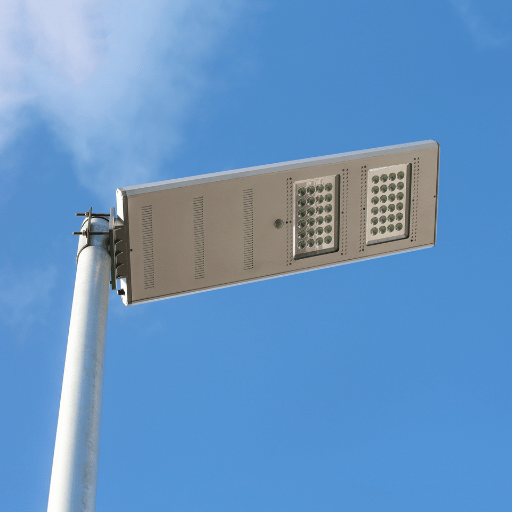
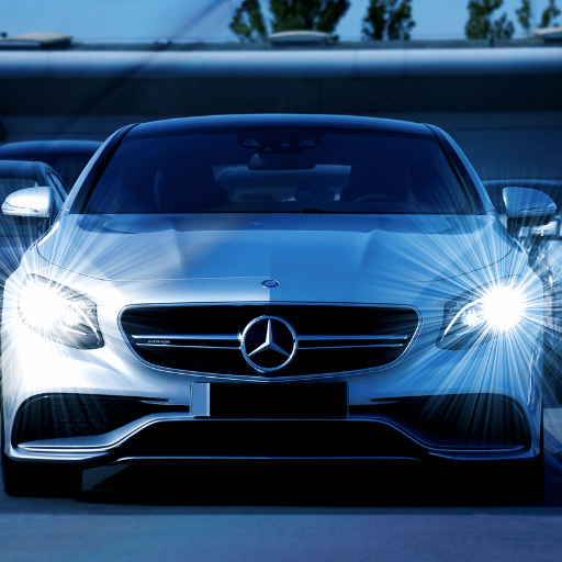
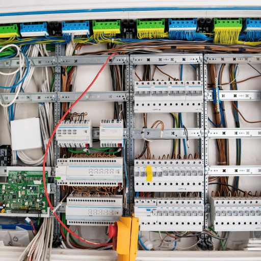
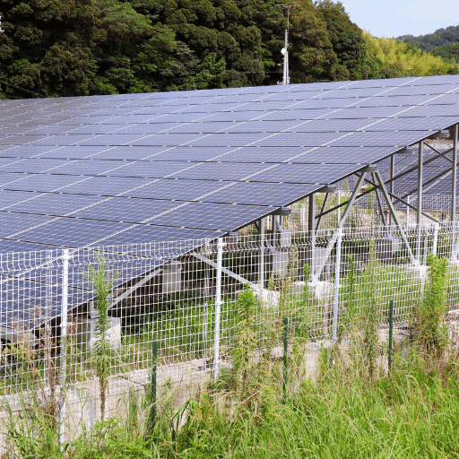
With its tight thermal and cost fit for so many applications, LEDs continue to be our largest single area of application. The physics are direct; cooler LEDs maintain their brightness over time, or a designers may drive them harder within a consistent thermal budget. In the automotive world – particularly in vehicular engine compartment and headlamp environments where the constant punishing ambient temperature makes FR-4 a risky choice – the metal base layer becomes the only reliable means to carry the driver’s heat down through an integrated path, keep a module within its operating specification and avoid any unpleasant under-hood surprises. This same physics extends to power conversion and new energy equipment where we use either copper-base or multilayer structures to push the highest currents and highest heats while simultaneously managing tight cost goals.
power converters represent our second largest application category and typically involve higher board heat, higher ambient temperatures and even higher operating voltages and currents than LED lighting applications. Our switching power supplies, DC-DC power modules and motor drives are designed to sink large amounts of heat from critical, high-current components into the metal-base thermal conductivity to prevent premature failure. Our heavy-duty aluminum substrate structure serves as the perfect board-level heat sink for the entire power stage, and the substantial copper thickness in our boards manage the higher currents and are a prime reason engineers will transition to a aluminum and copper-base board over an FR-4 as board density increases. High levels of performance for your thermal management can no longer be an option you can add to your board; that performance must be the board’s architecture.
Certifications & Quality Control (IPC Class 2/3, ISO 9001, UL, RoHS)
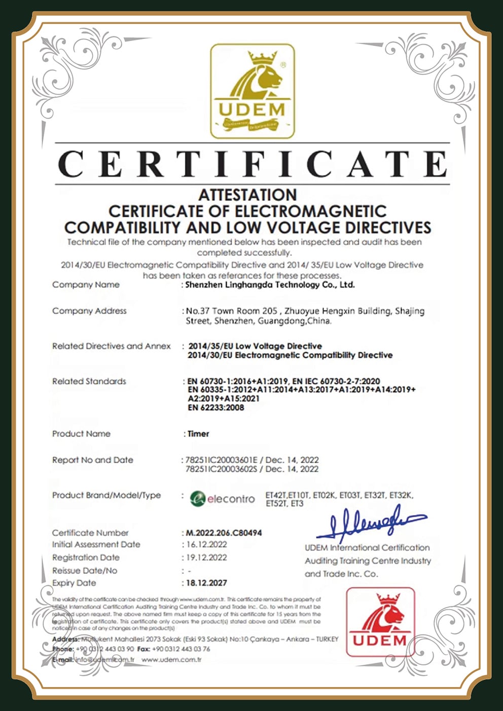
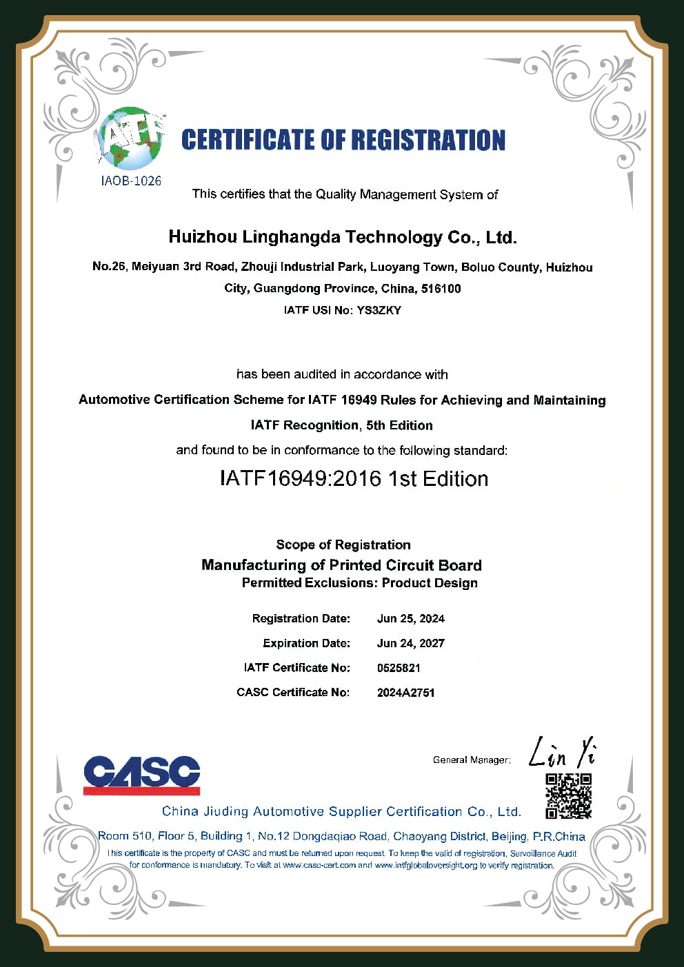
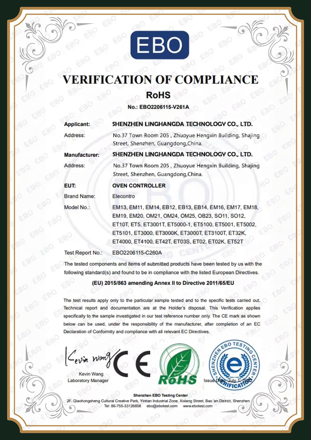
A new supplier relationship hangs in the balance of whether the board you qualify is the one you can acquire at volume. Our reference points are industry-agreed standards, not subjective description. All PCBark aluminum and metal core pcb are designed, fabricated, and inspected according to IPC-6012 (Rigid board specification and design) and validated to the IPC-A-600 visual criteria, within the framework of customer chosen IPC class (Class 2 or Class 3). Every PCB bark board passes through 100% electrical test. (quality system per ISO 9001:2015)
IPC-6012
Rigid board qualification
IPC-A-600
Class 2 / Class 3 acceptance
ISO 9001
Quality management
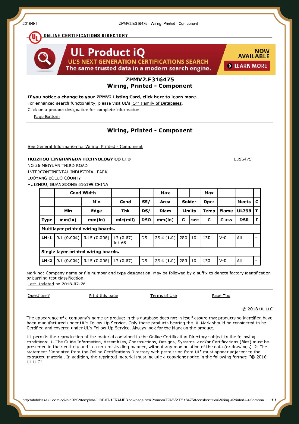
UL 94V-0
Flammability rating
RoHS / REACH
Material compliance
100% E-Test
Every board, every run
×
Advanced Aluminum MCPCB Engineering Tools
Aluminum PCB Thermal Resistance Estimator
Estimate junction-to-ambient thermal resistance and how much cooler your component runs on an aluminum MCPCB versus FR-4. First-order model for early board selection.
Launch Estimator
Aluminum MCPCB Capability Tier Selector
Map your design requirements to PCBark’s Standard, Best, or Maximum capability tier — and see instantly whether your spec is inside our production window before you send a Gerber file.
Launch Selector
MCPCB vs FR-4 + Heatsink TCO Comparator
A metal core board costs more bare — but FR-4 needs heatsinks, fans, and thermal vias to handle the same heat. Compare the loaded per-unit cost of both paths for your volume.
Launch Comparator
Aluminum PCB FAQ, Common Buyer Questions
It depends on the tier, layer count, copper weight, surface finish, and volume, a standard single-sided board is far cheaper than a 6-layer 5.0 W/m·K build. As a reference, metal core typically runs 2–4× an equivalent FR-4 bare board, though high-power designs often recover that by dropping heatsinks. FR-4 stays the cheapest PCB material, which is why it remains the default until heat forces the switch. Send your specs for an exact quote. (polymer-dielectric reference: USPTO US 2010/0012354 A1)
Standard FR-4 conducts heat at about 0.25 W/m·K, while a metal core PCB, also called a metal core circuit board, uses a thermally conductive dielectric of 1.0 to 5.0 W/m·K between the copper and an aluminum or copper base to move heat 8–9 times faster. The thermal conductivity of metal core PCB stacks is what cut thermal resistance from 61.56 to 39.1 °C/W in the TI LED test. FR-4 will be used for all signal based PCB’s or if you aren’t dealing with thermal management issues, metal core PCB can also be the PCB material choice when heat dissipation from components is the key issue; in addition, FR-4 will generally be less expensive until heat requires the change.
Both require separate handling-which are needed for manufacturing for: routing, drilling and V-scoring due to the metallic layer and making sure the dielectric adheres in order to avoid trapped voids but if the manufacturer has metal-core manufacturing capabilities then it can be done easily. A very common design mistake people make with this type of board material is treating the aluminum base as carrying current. The honest framing: aluminum core is for heat, not current. If a design need to carry high current on the board, and you’re looking for more power handling than is typical on aluminum, copper bus bars should be added for increased performance, not a thicker aluminum. Simply remember that when using aluminum, its sole function is for thermal transfer, not for current transfer.
No, as this causes an increased cost for thermal capabilities that aren’t needed in the designs. This board uses an aluminum MCPCB along with a high-conductance dielectric; as it has the same thermal and electrical qualities that will be found within a copper based board, it doesn’t make the case when the dielectric layer (1-8W/mK) is more of a bottleneck. This also brings it more into line with an alternative at approximately half the thermal characteristics of a copper or metal clad PCB at nearly the same price point.
At PCBark we manufacture total board thickness from 0.6 mm to 5.0 mm. Based on the tier and product you’ll receive, there’s the option for aluminum from 0.6 mm to 5.0 mm; it matters that we manufacture the best boards to meet our customer’s requirements. For use in smaller, contained LED boards, a thinner board may suffice, or for use in larger High power applications product requiring additional heat transfer then a thicker aluminum base might be more beneficial.
Yes, you get both off our standard and best lines (as listed above); all of our work come on one single process line. this reduces re tooling and can simplify manufacturing on our behalf, for us to build your product from prototypes all the way up to volume order. When supplying us your RFQ be sure to let’s know the amount of time you’ve to provide for production.