Get in touch with PCBark Company


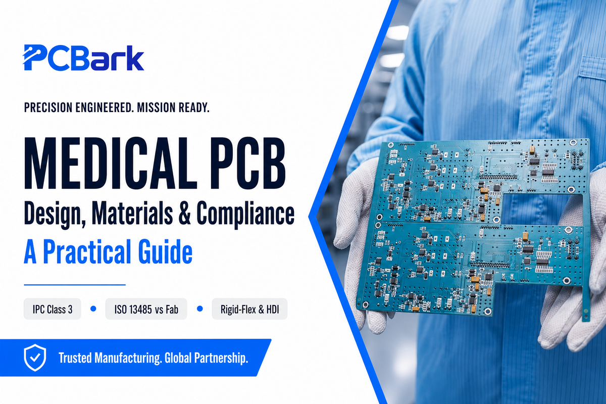
A medical PCB is a printed circuit board built and verified to the reliability, traceability, and biocompatibility levels that healthcare devices demand. The phrase “medical PCB” covers everything from a disposable glucose strip reader to the high-density board inside a CT scanner, but the engineering question is always the same: which design, material, and compliance choices keep a board working when a patient’s safety depends on it. This guide walks through medical PCB types, substrate selection, design rules, the standards that actually apply, manufacturing and inspection, and how to qualify a supplier – with one contrarian point most vendor pages get wrong.
The short answer: A medical PCB has to satisfy three separate layers of control – a device-level quality system (ISO 13485 / FDA QMSR), board-build reliability (IPC-6012 Class 3), and end-product electrical safety (IEC 60601-1). Of those three, the board fabricator owns only the middle layer, not the first. A fab does not need its own ISO 13485 certificate to legitimately supply a regulated device program.
Key Takeaways
- Your Device Is Your ISO 13485 ResponsibilityISO 13485 is a device manufacturer’s duty. The FDA’s new Quality Management System Regulation (QMSR), effective February 2, 2026, ties it to “finished device manufacturers” – not bare-board fabricators.
- Reliable Source: Even Without 13485, a Fabricator Can ComplyA non-13485 fab with IPC-6012 Class 3 + IATF 16949 + per-lot traceability + UL can legitimately feed a 13485 device program.
- Not Every Material is Ready for the HeatSubstrate choice is driven by the sterilization method and operating temperature, not by cost alone.
- Safety Standards are Design RulesIEC 60601-1 (Edition 3.2) sets creepage, clearance, and 2×MOPP isolation – a board design constraint, owned by the device team.
- Medical PCB Market OverviewDemand growth is real but rides on flexible and wearable electronics, not a standalone “medical PCB market.”
Quick Specs: Medical PCB at a Glance
| Reliability class | IPC-6012 Class 3 / 3A (medical addendum IPC-6012EM) |
| Layer count | 2 to 32+ (HDI any-layer for imaging/implantable) |
| Common substrates | High-Tg FR-4, polyimide (flex), PTFE, ceramic, metal-core |
| Safety standard | IEC 60601-1 Ed 3.2 (creepage/clearance, 2×MOPP); IEC 60601-1-2 EMC |
| Device QMS | ISO 13485 / FDA QMSR (held by the device OEM) |
| Sterilization | Autoclave 121–134°C / EtO / gamma |
| HDI floor | ~0.075 mm line/space; 0.10 mm laser microvia |
What Is a Medical PCB?
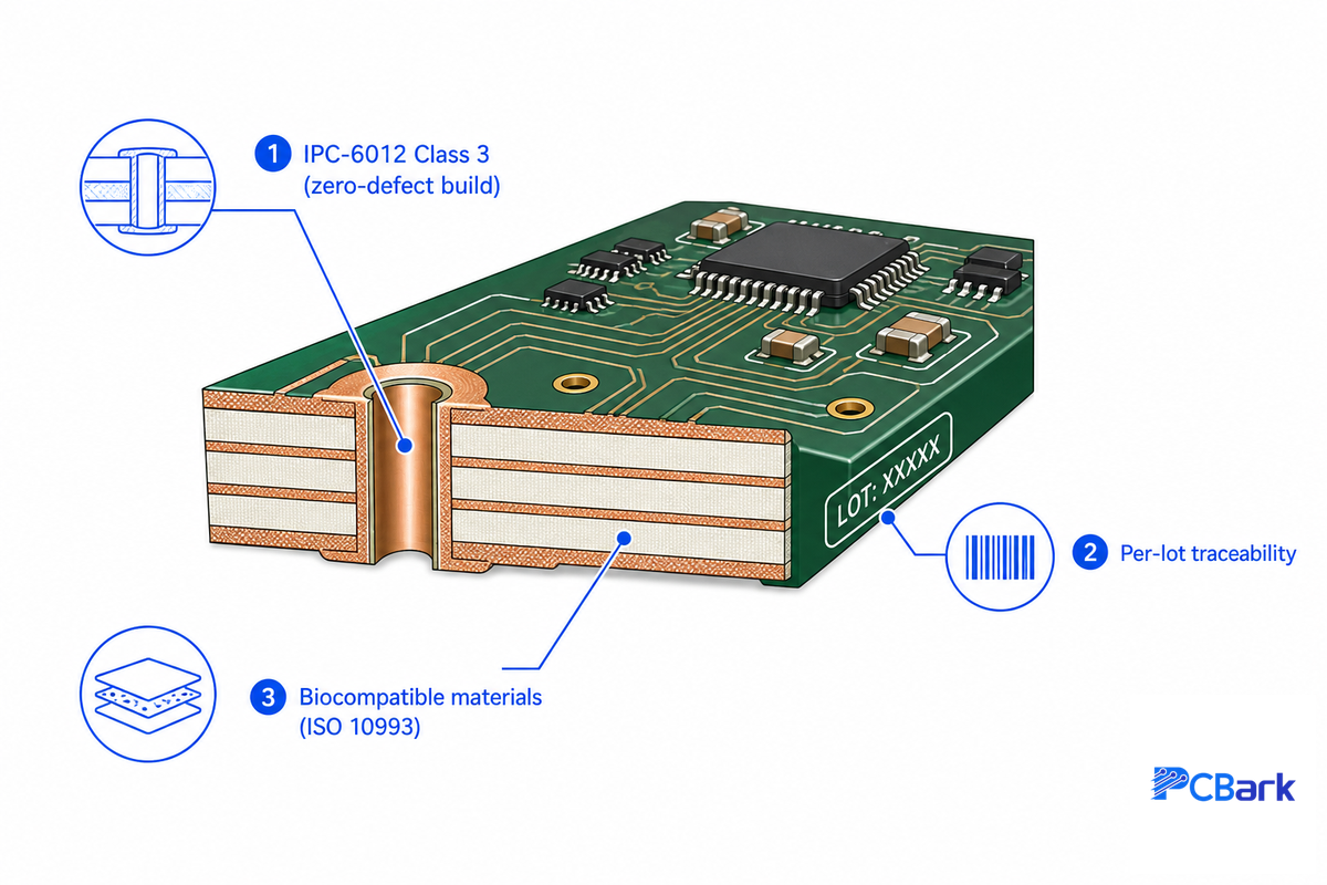
A medical PCB is a printed circuit board qualified for a medical device, which means it is held to a higher reliability class than a consumer board and carries documentation a hospital or regulator can audit. Three attributes set it apart from a standard commercial board: an IPC-6012 Class 3 build, per-lot material traceability, and biocompatibility.
Each attribute is concrete. A Class 3 build targets zero-defect, life-support performance; per-lot material traceability means any board can be traced to its laminate and copper batch in a recall; and a patient-contact board must use biocompatible materials evaluated under ISO 10993 and survive repeated sterilization.
Why the bar is higher is simple: a defect that’s a nuisance in a phone can stop an infusion pump or blank a patient monitor. Class 3 acceptance tightens the tolerances that matter for that – for example, plated through-holes must keep at least 25 µm of copper in the hole wall with no permitted voids, where a consumer Class 2 board would accept closer to 20 µm and minor imperfections. The practical consequence for a buyer is that “medical-grade” isn’t a marketing word; it’s a measurable set of build and documentation requirements you can write into a purchase order. Across the medical industry, these requirements for PCB build quality are what make medical printed circuit boards highly reliable enough for life-saving equipment. PCBs are commonly used in medical devices like pacemakers, infusion pumps, and imaging systems, and PCBs for the medical industry need to be extremely reliable — you will barely find medical devices without a printed circuit board inside, so a reliable medical PCB clears a far higher bar than a consumer board.
Types of Medical PCBs and the Devices They Power
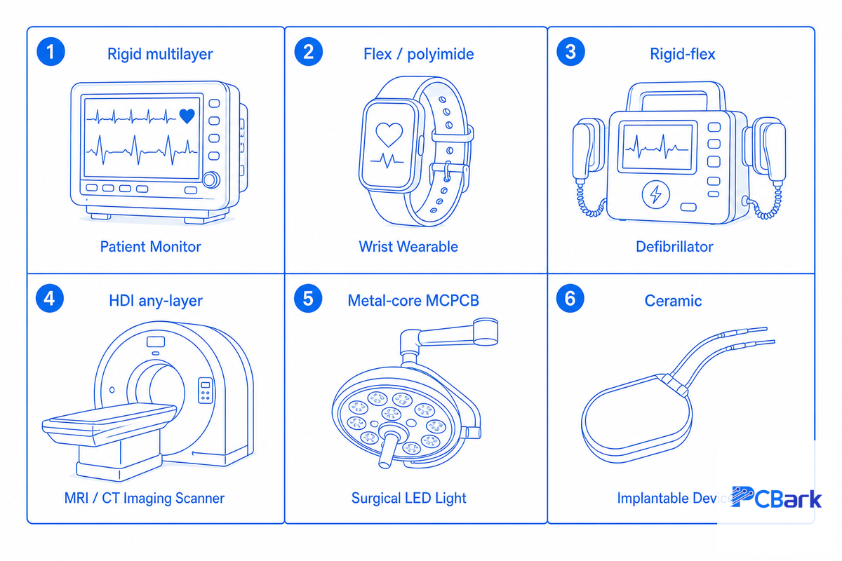
Your device form factor and environment determine which kind of PCB you need. Most medical equipment on the bench or in a cart use rigid PCB, but wearables, implantables and folded systems rely on flex and rigid-flex while imaging systems require HDI board for their high-density pin-out processors. Refer to the chart below for an application based guide to PCB construction types:
| Board Type | Typical devices | Why this construction |
|---|---|---|
| Single/double-sided rigid | Disposables, simple sensor readers | Lowest cost, fastest 1–5 day turn for low complexity |
| Rigid multilayer (4–12 layer) | Patient monitors, infusion pumps, bench analyzers | Stable platform, mature Class 3 process |
| Flex (polyimide) | Wearable monitors, glucose sensors, endoscope tips | Bends into the body; survives 100,000+ flex cycles |
| Rigid-flex | Hearing aids, defibrillators, catheter electronics | Eliminates connectors — fewer failure points in a sealed device |
| HDI / any-layer (up to 32 layer) | MRI/CT imaging, ultrasound, DNA sequencers | High pin-count BGAs, 0.10 mm microvias, 0.075 mm line/space |
| Metal-core (MCPCB) | LED surgical lighting, phototherapy, laser drivers | Conducts heat away from components running above 100°C |
| RF / microwave (PTFE) | Wireless implants, telemetry, RF ablation | Low dielectric constant (~2.1) for clean high-frequency signals |
| Ceramic | Active implants, hermetic sensor packages | Survives 350°C+, biostable, hermetic seal compatible |
| Heavy-copper (≥3 oz) | Electrosurgical generators, defibrillator output | Carries high current and dissipates heat in one layer |
One common shop floor tip is this: The more device wear or implantation becomes part of the design, the more likely it’s that the board will evolve from rigid to flex/rigid-flex in PCB technology because of all the potential failure points that can be designed away by eliminating connectors. Certain implantable devices, as mentioned in U.S. Patent No. 8,147,486, go one step further, using the biocompatible material to form the entire flexible board to eliminate electrical interfaces by making it capable of direct contact with tissue. Rigid boards still anchor most bench equipment, while flex or rigid-flex now defines the wearables — from blood glucose monitors to pacemaker leads — that dominate modern medical devices. Because PCBs are common to nearly every modern device, the standard set that regulates medical electronics is what makes an extremely reliable board auditable.
Medical PCB Materials: The Substrate Decision Ladder
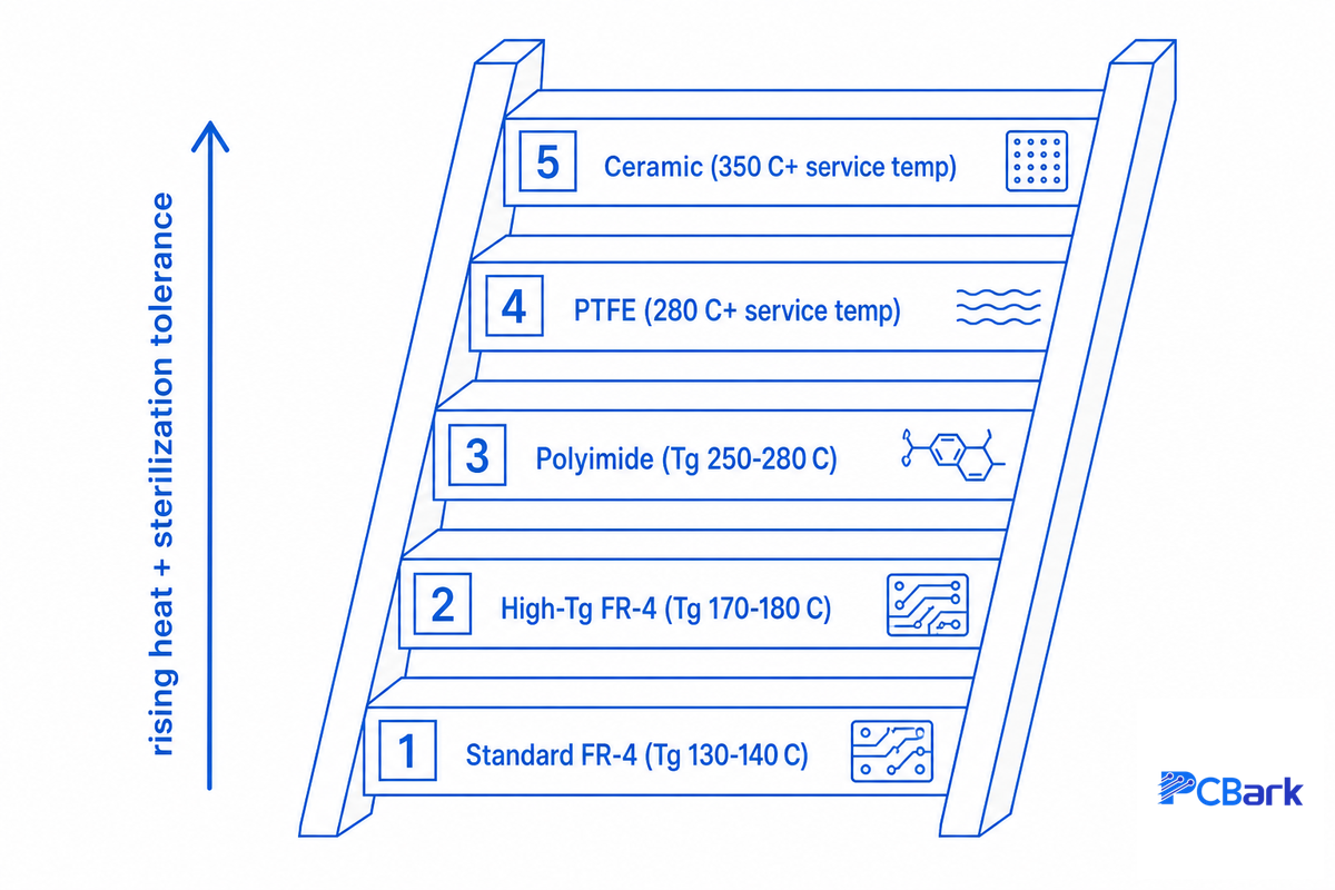
When choosing PCB substrates for medical applications, less attention is paid to cost, and more attention is paid to these two questions: how will the board operate from a temperature perspective, and what method will be used for sterilization?
You should only use a board material as advanced as the application warrants. There’s no sense using a more exotic board material like ceramic, for example, if a high-Tg FR-4 will withstand the process stresses; using advanced materials is unnecessarily costly and drives up leads times.
The 5-Tier Substrate Decision Ladder
Every step up the board material substrate ladder involves more cost, but comes with added thermal and electrical performance. As long as you can maintain patient safety and still manage thermal issues and ensure compliance with electrical standards, choose the lowest level of sophistication that meets the design need and the sterilization method. Selecting the right PCB laminate materials early keeps later changes cheap.
| Substrate | Tg (glass transition) | Choose it when |
|---|---|---|
| Standard FR-4 | 130–140°C | Non-sterilized, room-temperature electronics |
| High-Tg FR-4 | 170–180°C | Autoclave-adjacent heat, lead-free assembly, thick stack-ups |
| Polyimide | 250–280°C | Flex/rigid-flex, high temperature, high comparative tracking index |
| PTFE | 280°C+ | High-frequency RF telemetry, low dielectric constant (~2.1) |
| Ceramic / metal-core | 350°C+ | High thermal load, implant-adjacent, hermetic needs |
📐 Engineering Note
Substrate choice comes down to just two properties: the heat resistance, as represented by the glass-transition temperature (Tg), and the insulation’s resistance to tracking under electrical stress, as reflected by Comparative Tracking Index (CTI), a value specified according to iec 60601-1 standards. Whereas conventional FR-4 substrate materials provide a CTI value on the order of 175 V and a Tg around 130°C, a higher grade like a polyimide provides for the greater CTI value of about 600 V, and is common in the design of defibrillators and patient isolation circuits requiring a high voltage isolation level. Sterilization imposes its own ceiling – it can raise board operating temperatures from 121 to 134°C for 3 to 30 minutes with the steam sterilization process, or the ethylene oxide process at 55°C.
If a substrate has a softening point of 130°C, for instance, it’s unsuitable regardless of the electrical properties. parylene-C serves as a protective, moisture-impervious coating for the assembled medical device when tissue contact or biocompatibility is needed; typically, it’s the conformal coating and not the underlying PCB material that satisfies contact standards. Biocompatibility itself is determined on a per-device basis-devices that are inserted into the human body, directly or indirectly, are reviewed according to the ISO 10993-1 standard for toxicological compatibility as a function of contact time and place of contact, not simply the maximum heat generated under normal operations. Therefore, an analysis of board material properties should clarify what substrate has adequate performance, whereas the ISO 10993-1 standard should confirm material biocompatibility.
Design Requirements for Medical PCBs
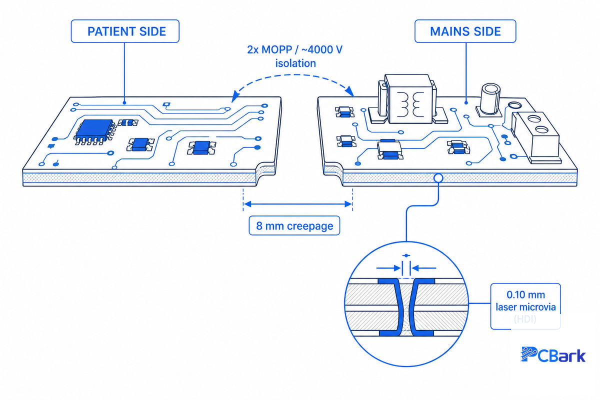
Beyond standard design-for-manufacturing practices, medical PCB design mandates patient-safe DFM practices, which includes compliance to creepage and clearance to provide isolation, the optimization of electromagnetic interference, design with miniaturization principles using HDI, and providing easy design for testability on each manufactured PCB assembly.
What are the design requirements for a medical PCB?
Medical PCB design layers four patient-safety constraints on top of standard DFM: creepage and clearance for isolation under IEC 60601-1, electromagnetic compatibility, HDI miniaturization, and design-for-test access. Get the isolation barrier and EMC right at layout time — both cost far more to fix once the enclosure is tooled.
To support medical applications, any PCB must meet all the specified IEC 60601-1 requirements regarding spacing: in excess of a consumer PCB’s 0.5-mm gaps required for 4,000-V isolation across a barrier under up to 2×MOPP (2 Means of Patient Protection) with a barrier clearance of 8 mm or more. Every board must also clear the EMC requirements stipulated in IEC 60601-1-2 (both emit the mandated interference and tolerate a clean board when close to other medical instruments). Note that IEC 60601-1 is the overall safety standard; its particular applications are specified within subsidiary standards like 60601-1-2 for EMC testing; particular device types may also carry other specifics (i.e., a defibrillator and MRI board have differing specifics on the base standard). Beyond that, medical imaging and diagnostics often venture into the HDI (high-density interconnect) arena-such as, ultra fine laser microvia drilling down to 0.10 mm, the use of via-in-pads under BGAs (ball-grid arrays) and maintaining specific controlled-impedance high-speed routing within ±10 percent tolerance. Finally, a need for clearly demarcated test points or boundary-scans will exist for in-circuit and flying-probe assembly tests. As a rule of thumb, any medical PCB will need careful attention at layout to isolation and EMC requirements, as correcting such flaws at assembly can be ruinously expensive.
Often the isolation barrier is the very first aspect of a new medical board layout that fails a regulatory review. Isolating the mains-powered circuit from any part to the body is going to need some generous creepage and clearance-going beyond what’s required for just operating voltage and enclosure “pollution degrees”; in consequence, seasoned design reviews invariably start with drawing an isolation barrier and route all tracks around that-instead of trying to cram one into a packed board design at the last minute. Good signal integrity on high-speed signal paths, clean plated through-hole (PTH) transitions, and disciplined DFM and DFA practices are what separate experienced medical PCB designers from generalists.
Standards and Compliance: The Medical PCB Compliance Stack
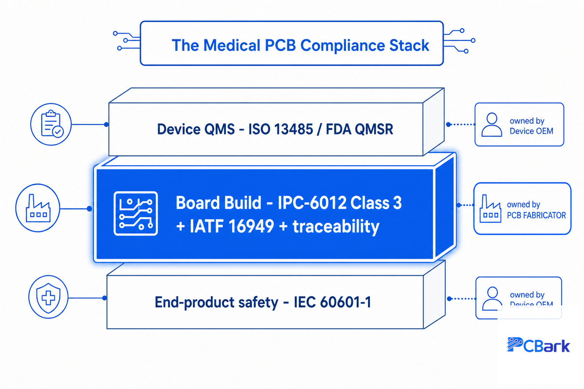
Does your PCB supplier need ISO 13485? Vendor websites almost always imply that it does. The honest answer, read from the official documentation, is more useful: a medical device carries three separate layers of compliance, and only one of them, the middle layer, is the fabricator’s responsibility.
The 3-Layer Compliance Stack
The table should be read from top to bottom; only the middle tier is the fabricator’s.
| Layer | Standard | Who owns it | What it proves |
|---|---|---|---|
| Device quality system | ISO 13485 / FDA QMSR (21 CFR 820) | Device OEM | Design history, risk management, market authorization |
| Board build | IPC-6012 Class 3 + IATF 16949 + per-lot traceability + UL | PCB fabricator | Zero-defect build, material control, repeatability |
| End-product safety | IEC 60601-1 / IEC 60601-1-2 | Device OEM (system) | Patient electrical safety, EMC |
Legally and factually, however, there is no wiggle room: ISO 13485 has nothing directly to do with how device components need to be specified, only with the manufacturer of the finished devices and with how the supply-chain must be monitored to insure the finished goods can make claims related to the OEM standards. FDA regulation itself (21 CFR Part 820 – a subset of its Quality Management System Regulation, QMSR – is the direct and pertinent rule of the day, as updated to include ISO 13485:2016, effective February 2, 2026) specifies requirements for finished devices-and by extension their OEM manufacturers-that implement the regulation, not companies providing any subcomponents. The underlying law states, however, that “the Quality System Regulation… does not directly apply to component or parts manufacturers,” even though it “encourag[es]… [them] to consider [the rule] as appropriate”. Many independent research outlets agree, in a practical sense, that a company does not need a ISO 13485 Certificate to legally put an FDA registered medical device on the market, and it is common knowledge amongst PCB procurement experts that the agency doesn’t push any particular chain actor to handle or secure any of these necessary levels. These industry standards — IPC from the electronics industry, ISO 13485 from the International Organization for Standardization, and RoHS, the Restriction of Hazardous Substances — together form the detailed quality management system that healthcare and medical applications depend on. IEC 60601-1 regulates the design and performance of medical electrical equipment, while the build process to ensure reliability sits with the fab; the RoHS directive adds its restriction of hazardous materials. That yields PCBs that meet recognized standards even when the fab itself is not ISO 13485 certified.
What this means in practice is that although they might not show certification for the medical regulatory frameworks (i.e., ISO 13485 ), an IATF 16949 Certified fabricator using IPC-6012 Class 3 standards can make the build of record if it provides per-lot traceability of components used to make their PCBs and if their customer (the OEM) applies a sound OEM vendor/supplier quality management system to track each other.
“The mistake we see most often is a buyer rejecting a perfectly capable Class 3 fab because it lacks an ISO 13485 certificate, then paying a premium for a 13485 logo that adds nothing to the board. What actually de-risks the board is Class 3 acceptance, IATF 16949 process discipline, and a traceability record that survives an audit.”
⚠️ One honest caveat
Some authoritative voices in the industry argue that ISO 13485-style controls should extend down into the fab supply chain, and some OEM programs do contractually require it. So “a fab does not legally need ISO 13485” is true, while “no customer will ever ask for it” is not. The accurate framing is that ISO 13485 is the device OEM’s duty plus a possible commercial expectation, one a non-13485 fab meets through comparable, auditable controls.
Manufacturing, Assembly and the Qualification Gauntlet
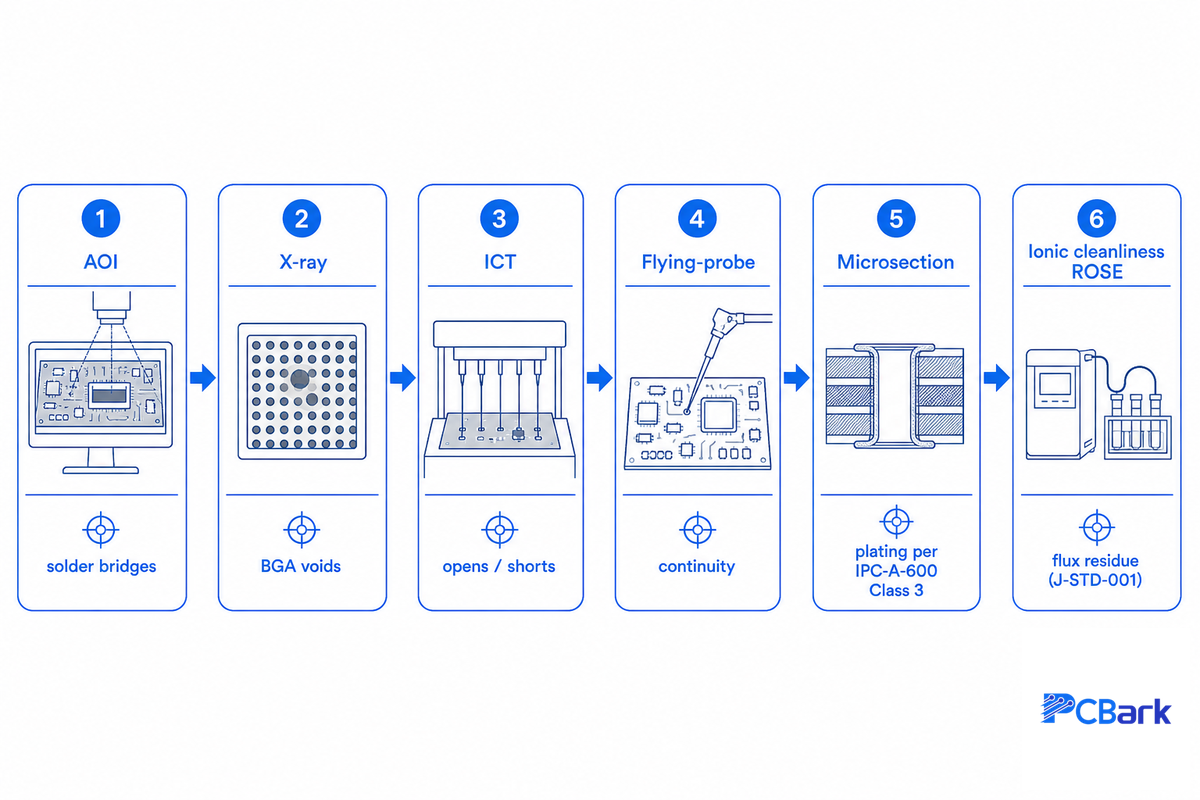
So, what transforms a circuit board layout into an auditable medical-grade component? Not a single step, but a cascade of checks, each one designed to flag a specific defect type. Knowing which specific inspections should be part of every medical lot build confidence that the boards will pass at incoming inspection and function correctly out in the field. We refer to the complete set of checks in this process as the qualification gauntlet.
The 6-Test Qualification Gauntlet
With each inspection targeting a unique set of defects missed by others, a medical lot should ideally pass through all six tests rather than rely on any one individually.
| Inspection | Catches |
|---|---|
| AOI (automated optical) | Solder bridges, missing/misaligned components, polarity |
| X-ray | Voids under BGAs, hidden joints, internal layer faults |
| ICT (in-circuit test) | Wrong values, opens/shorts, functional faults |
| Flying-probe | Net continuity on low-volume boards without a fixture |
| Microsection | Plating thickness and via integrity, per IPC-A-600 Class 3 |
| Ionic cleanliness (ROSE) | Residual flux that causes long-term corrosion, per J-STD-001 |
Traceability is the common thread that ties the gauntlet together. For our medical work, lot traceability is maintained including records for laminate, copper batch number, dates of manufacture, and inspection data, enabling an individual board to be traced back through the supply chain should a recall or an investigation into field failures be required – the same type of per-lot tracing required by an OEM to approve a non-13485 fab as an approved supplier. Assembly itself is conducted within a controlled environment; assemblies of products used in or around the human body are frequently produced in cleanrooms (ISO Class 6-7) with soldered components subject to J-STD-001 acceptance criteria. In our manufacturing facility eight SMT lines can deposit up to 9 million components per day on each line and pass each board through controlled reflow (245-260°C), in-line automated optical inspection (AOI), x-ray inspection and in-circuit test (ICT) within an average of 60s, allowing the gauntlet to be run directly inline, not as a separate post-assembly batch. From prototype through volume, our PCB fabrication and assembly manufacturing process is built to ensure reliability when making medical devices for hospitals and other medical facilities.
How to Choose a Medical PCB Manufacturer: RFQ Readiness Checklist
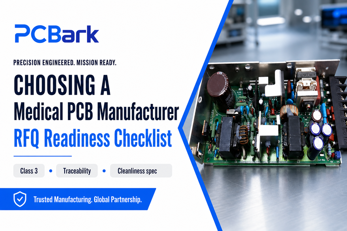
When selecting a medical-grade PCB manufacturer, two criteria should stand out: is your request for proposal so detailed that the quote you receive is real and not just a place-holder? and does the manufacturer exhibit these red flags distinguishing them as a true Class 3 shop rather than just a site printing “medical” on their website? Assemble this checklist before even asking for a quote.
The Medical PCB RFQ Readiness Checklist
- Performance class clearly indicated (e.g., IPC-6012 Class 3; NOT simply “high reliability”)
- Stack-up clearly delineated along with associated Gerbers/ODB++ and any needed controlled-impedance callouts
- Cleanliness requirements and acceptance criteria (e.g., J-STD-001 with applicable ROSE test limits)
- Level of traceability required (e.g., all material batch information, lot traceability to manufacturing dates)
- Sterilization method to confirm material compatibility
- Written verification of pertinent certifications (e.g., IPC-6012 Class 3, IATF 16949, UL, ISO 9001 certifications)
Red flags are equally stark. A facility that cannot provide per-lot traceability; that speaks “Class 3” but accepts “Class 2;” or that fails to take micro-sectioning for a medical multilayer PCB. Do not, on the other hand, filter out a quality fab because it doesn’t hold its own “ISO 13485 Certificate”-that responsibility sits with the OEM under 21 CFR Part 820 (as discussed above).
See our medical PCB capabilities section for a breakdown of devices with these capabilities; or, visit our design for aerospace guide to see this same discipline applied to an adjacent, high-reliability application area.
Where Medical PCB Manufacturing Is Heading
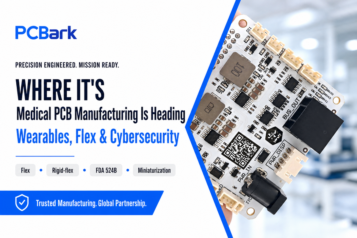
Medical PCB manufacturing in 2026 is being reshaped by two forces: care moving onto the body, which pushes demand toward flexible and rigid-flex boards, and new FDA cybersecurity rules, which make connected, traceable boards the norm. For your next design, lean toward flexible construction and budget cybersecurity documentation from the start.
Two forces will shape the medical PCBs of 2026 aren’t growth-market size-but architecture and regulation. And only two really count for your next medical electronics project: Care is already moving out of the doctor’s office, onto patients’ bodies and into their homes; the rise of implantable and wearable monitoring devices, mobile diagnostic equipment, and home medical equipment from continuous-glucose monitors to portable ventilators will increasingly drive the choice of flexible and rigid-flex over traditional rigid PCBs and will increase the premium for smaller dimensions. Regulators have also added connectivity as an “additional duty”: Under the FDA’s Section 524B requirement that any “cyber device” come with a documentation on its cybersecurity posture as part of the premarket submission (effective March 29, 2023, with Refuse-to-Accept policies since October 2023), there will be a need for still more connected boards, still more attention to EMC and a greater need for traceability throughout the product life cycle.
Market data aligns with that direction, but view it as context, not predictive on the med device side — there’s no standalone “medical PCB market”, but the flexible PCB sector from which medical wearables draw will jump from ~$23.9Bn to ~$50.9Bn by 2030 (a ~13.7% CAGR); the more expensive rigid flex is near 6.8% growth rate. Bottom line, if you’re designing a 2026-2027 device, design for flex/rigid flex earlier than you might currently be thinking, budget for cybersecurity documentation into your overall product development program, don’t expect it will just pop in at submission time. Applications in the medical field keep expanding across healthcare and medical applications, so expect the next wave of types of PCBs to skew toward thinner, flexible, sensor-ready boards.
Frequently Asked Questions
What is PCB in medical?
View Answer
The “PCB” in a medical electronic device means Printed Circuit Board. This board is either rigid or flexible, carrying and wiring together the components and chips within the medical machine you will find within a hospital or physician’s office that monitor or help care for the health of an individual; such as pumps, images and heart monitoring systems. The PCBs will be produced to meet medical standards like IPC-6012 Class 3 to ensure there is no failure that can impact or end a patient’s life. Note that in clinical settings the acronym PCB can also refer to other things entirely, so confirm the context.
What is a PCB test in medical?
View Answer
This circuit of automatic vision and physical inspections carried out in-circuit test PCB testing will ensure your medical board works as intended: • Auto Optical Inspect (AOI) is used to check placement and joint • X-ray tests hidden joins • in-circuit testing or flying probes detect electronic errors • Test of micro-section plating integrity • ROSE/ionic-cleanliness tests residual contamination. All above standards tested against J-STD-001 and IPC A-600 acceptance, and the final result will be recorded for lot traceability for your boards.
Does a medical PCB manufacturer need ISO 13485?
View Answer
It’s no legal requirement for the bare-board PCB manufacturer to own a ISO 13485 Certificate. The FDA QMSR that includes the ISO 13485 process from February 2026 falls under the final device manufacturer, not the PCB shop. A non-13485 compliant manufacturer meeting IPC-6012 Class 3, with IATF 16949 process controls, UL, and lot-level traceability can supply boards for a 13485 compliant device design. That being said, keep in mind some end customers contractually insist on a chain down to a Class 3 supplier, so ask them for their supplier controls.
What materials are used in medical PCBs?
View Answer
Available substrate materials include hi-Tg FR-4, polyimide for flex boards and high temperature usage, PTFE for radio telecommunications applications, and for the highest thermal loads, ceramic or metal core substrates. Biocompatible conformal coating is then applied to any patient-contact circuit boards, often parylene-C.
What IPC class is required for medical PCBs?
View Answer
The IPC-6012 Class 3 is the highest performance class and is routinely applied, with IPC-6012EM often the reference in designs where the equipment can support life. The lower specification of ipc-6012 Class 2 is seldom appropriate in a situation where life support is part of the system operation.
How much does medical PCB assembly cost?
View Answer
There isn’t a single flat price for a medical device circuit board – the price varies by count of the layers (high number implies higher complexity), the kind of substrate material (PTFE is more expensive than FR4), the level of IPC-6012 Class 3 verification desired, the extent of traceability offered (lot-level vs. each-board), and of course the quantities required. Provide each customer an accurate quote once a complete request for quote (including class requirements, stackup details, specifications for cleanliness and lot tracing, planned sterilization process, etc.) is provided. Although IPC-6012 Class 3 requirements do entail additional checks and paperwork over consumer class PCBs, it doesn’t drive anywhere near the cost of trying to over-spec a unnecessary certification.
Building your medical device and looking for a Class 3 partner that can provide the trace you require for complete lot tracking and process control?
Why We Wrote This Guide
PCBark fabricates and assembles boards to IPC Class 3 with IATF 16949 process control, UL recognition, and per-lot traceability, and, deliberately, without holding ISO 13485, because that certificate belongs to the device OEM’s quality system, not the fab’s. We wrote this guide because the “you must use a 13485 fab” claim costs medical buyers real money and narrows their supplier pool for no compliance gain. Reviewed by the PCBark technical team.
References & Sources
- Quality Management System Regulation (QMSR)U.S. Food & Drug Administration
- Cybersecurity in Medical Devices (Section 524B FAQs)U.S. Food & Drug Administration
- 21 CFR Part 820, Quality System RegulationU.S. Electronic Code of Federal Regulations
- ISO 10993-1 Biological Evaluation of Medical Devices (FDA Guidance)U.S. Food & Drug Administration
- IEC 60601-1 Medical Electrical Equipment, General Requirements for SafetyInternational Electrotechnical Commission
- IEC 60601-1 Amendment 2 (2020)UL Solutions
- IPC-6012 / IPC-A-600 Acceptability StandardsIPC (Association Connecting Electronics Industries)
- US Patent 8,147,486: Medical Device with Flexible Printed CircuitUSPTO