Get in touch with PCBark Company


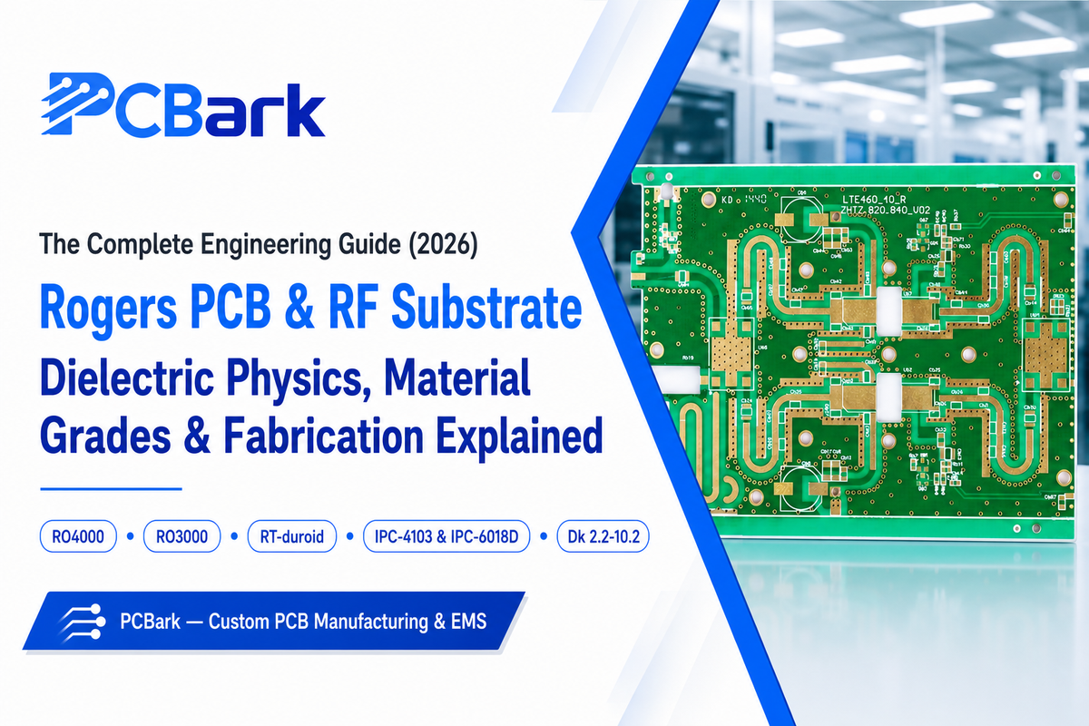
Quick Specs
| Common material families | Ceramic-filled hydrocarbon (RO4000), ceramic-filled PTFE (RO3000), pure PTFE (RT/duroid) |
| Dielectric constant (Dk) range | 2.2 – 10.2 depending on grade |
| Cost vs. standard FR4 | Roughly 3–8× per panel, grade-dependent |
| Governing base-material standard | IPC-4103 (vs. IPC-4101 for FR4) |
| Governing qualification standard | IPC-6018D (finished high-frequency/microwave board performance) |
A Rogers PCB is a printed circuit board fabricated on an engineered RF substrate material for reliable, high-frequency dielectric properties-so well-established that its supplier’s name, “Rogers,” is a stand-in for any member of the class, akin to how “Kleenex” stands in for tissue. This ambiguity unfortunately breeds confusion at the design level: many engineers assume “Rogers” and “RF substrate” are synonymous, though Rogers Corporation is merely one vendor in the broad category of ceramic-filled and PTFE-based materials.
The Rogers PCB materials family are ceramic-filled hydrocarbon, ceramic-filled PTFE, or pure PTFE laminates engineered for high-frequency stable dielectric constant and low signal loss above approximately 1-2 GHz. Their Dk values range from 2.2 to 10.2, and their cost on a per-panel basis is comparable to standard FR4 at 3 to 8 times that. Selecting the appropriate material depends on your frequency requirements, loss budget, and thermal constraints.
What you’ll get from this guide:
- Why dielectric constant and loss tangent actually control signal integrity-not just what the numbers are
- The real chemistry differences between PTFE, ceramic-filled hydrocarbon, and ceramic-filled PTFE materials
- An honest frequency-and-loss-budget framework for deciding whether you need Rogers/PTFE at all
- How these boards are actually fabricated, tested, and qualified-details most vendor pages skip entirely
What Is a Rogers PCB? RF Substrate Materials Beyond the Brand Name
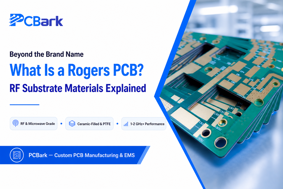
When engineers go shopping for a Rogers PCB, most end up on the product page of a single company’s laminates. That’s too narrow a definition for what’s actually available. “Rogers PCB” is just the brand name that’s shorthand for any circuit board built on a specialized RF substrate, or a laminate engineered specifically to hold a stable dielectric constant and low signal loss well beyond the 1-2 GHz cutoff above which standard FR4 can no longer reliably function.
Chandler, Arizona-based Rogers Corporation just so happens to be the primary provider of these RF materials, hence the generic designation – it’s the same reason that “Google” became a verb.
This distinction matter for two primary reasons. First, the “RF substrate” category includes several real alternatives, other manufacturers of PTFE-based laminates, various ceramic PCB platforms, and other specialty thermoset materials that are often superior to a specific Rogers grade for a particular application. More usefully, second, understanding why Rogers-type materials perform differently from FR4 enables engineers to choose a material based on its actual electrical and thermal merits instead of a familiar brand name.
Rogers’ Advanced Connectivity Solutions materials portfolio is one of the most established lines of advanced materials engineered specifically for high frequencies, consisting of three core chemistry families: ceramic-filled hydrocarbon (RO4000 series), ceramic-filled PTFE (RO3000 series), and pure PTFE (the RT/duroid family). Each of these material chemistries offers distinct tradeoffs in cost, manufacturability, and electrical performance; we clarify this taxonomy below, since no fabrication guide we consulted structured them by underlying chemistry, choosing instead to use series designations.
If you’ve already identified you need Rogers-grade material, and want to find fabrication pricing, capability, then look to the PCBark Rogers PCB manufacturing page, where we cover grade selection, capability levels, and RF quoting. But this guide discusses the underlying material science and design choices that should be made prior to having that discussion.
PCB Material Basics: From Copper-Clad Laminate to RF Substrate
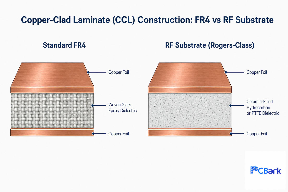
At its root, any rigid PCB begins its life as a copper clad laminate (CCL, more formally written copper-clad laminate) – a sheet of an insulating dielectric material with one or two surfaces clad with copper foil. An RF substrate (such as Rogers-class) differs from your typical FR4 material solely within the chemistry of the dielectric layer – there’s no fundamental difference in how it’s made.
For FR4, the dielectric is an epoxy resin that has been impregnated into a woven-glass cloth, providing good mechanical strength and acceptable electrical performance for digital logic and low-frequency analog designs. RF substrates substitute the FR4 epoxy/glass with one of the following dielectric systems: a hydrocarbon-based resin with embedded ceramic particles (which eliminates the disruptive fiberglass weave), a ceramic-filled PTFE composite, or a pure PTFE that’s reinforced with a random pattern of micro-glass fibers or woven glass fibers. These substitutions yield a more precise and more stable dielectric constant and reduce the dielectric loss tangent – the two key properties that we’ll expand upon in the following section.
In practice, if your design calls for “Rogers PCB” or “RF substrate,” you’re asking for a dielectric system, based on a different resin/reinforcement formulation than FR4 epoxy/glass, but laminated onto a similar piece of copper foil to provide electrical properties unobtainable with FR4 when your operating frequencies rise above a few GHz. This base-material distinction is codified in IPC-4103, the governing specification for RF/microwave laminate materials, versus IPC-4101 for FR4-class materials.
Dielectric Constant and Loss Tangent: Why These Two Numbers Control Everything
When you read a PTFE-based or Rogers-based dielectric datasheet, you’ll likely find a pair of prominent numbers right at the top, typically listed as “Dk” and “Df,” or “dielectric constant” and “dissipation factor” / “loss tangent.” Many data sheets will go no further in explaining the relevance of these numbers; that they’re significant is due to what they govern from a physical perspective, not because a data sheet says so.
Dielectric constant determines the speed at which electrical signals travel through the dielectric medium, and together with trace geometry it also sets the impedance (Z0) of any transmission line built on it. A high dielectric constant slows down the signal, and decreases the required trace width for a specific impedance (say, 50 Ω), although it also increases sensitivity of that impedance to manufacturing tolerances. Loss tangent measures the amount of energy that the dielectric itself will dissipate into heat as a wave travels through it – this figure represents a floor to the trace loss, which can’t be reduced by optimizing conductor losses.
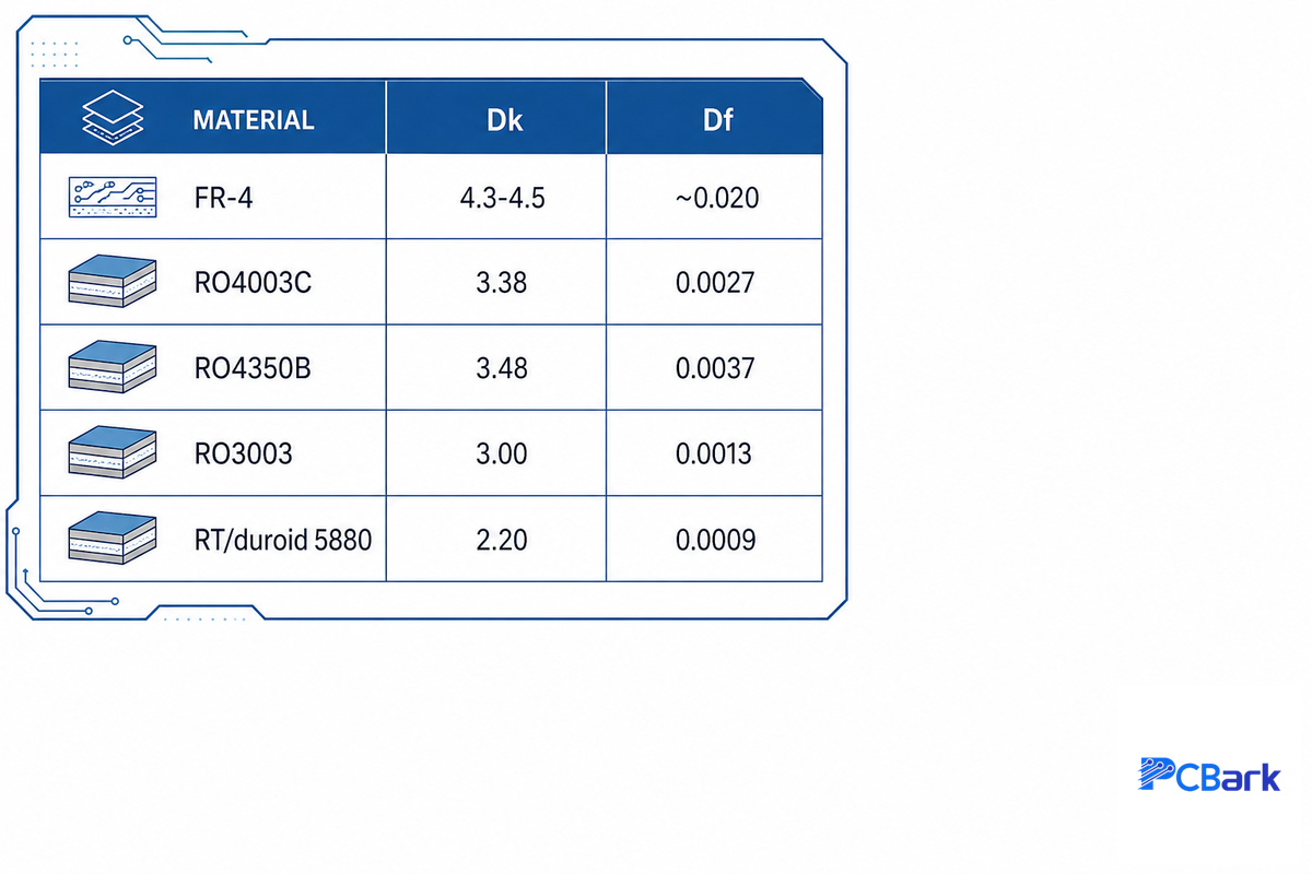
So, a dielectric material that boasts a Dk of 3.38 and a Df of 0.0027 (Rogers RO4003C, per the manufacturer’s own Rogers PCB material datasheet) would propagate a 10 GHz signal through its structure far more efficiently than standard FR4 with its characteristic Df around 0.02; the physical cause of the loss in the dielectric is the process of dielectric polarization, which is a function of Df, and increases with frequency. That’s why RF substrates matter more at 24 GHz automotive radar sensors than at 900 MHz.
A small disclaimer of honesty: Dk and Df aren’t frequency- or temperature-invariant constants. Rogers’ own datasheets specify a reference test condition (typically 10 GHz) precisely because both properties drift somewhat across frequency and temperature – independent measurements of PCB dielectrics across 30-40 GHz and -50°C to +70°C confirm real variation outside that reference point. Treat datasheet values as accurate at the stated test condition, not as universal constants.
| Material | Dk @ 10 GHz | Df (loss tangent) | Relative cost vs. FR4 |
|---|---|---|---|
| FR-4 (reference) | 4.3–4.5 | ~0.020 | 1× |
| RO4003C (ceramic-filled hydrocarbon) | 3.38 ±0.05 | 0.0027 | 3–4× |
| RO4350B (ceramic-filled hydrocarbon) | 3.48 ±0.05 | 0.0037 | ~1.2× RO4003C |
| RO3003 (ceramic-filled PTFE) | 3.00 | 0.0013 | 6–7× |
| RT/duroid 5880 (pure PTFE) | 2.20 | 0.0009 | 8× |
Source: Rogers Corporation published datasheets (RO4003C values independently verified against the manufacturer’s current datasheet during research for this guide); cost multiples are industry-typical ranges, not fixed pricing.
PTFE, Ceramic-Filled Hydrocarbon, or Pure PTFE? The RF Substrate Material Families
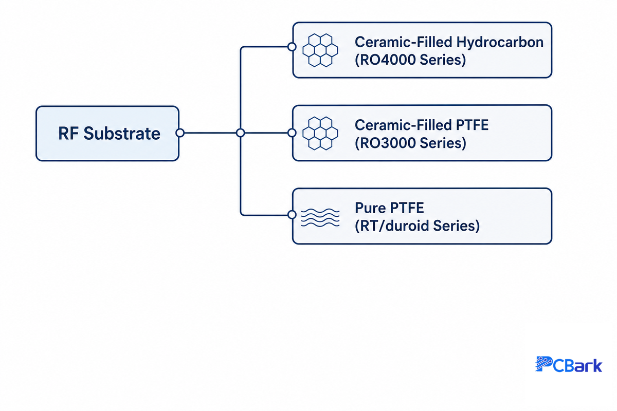
You’ll also see “PTFE PCB” and “Teflon PCB” used as search terms for this same material class – Teflon is DuPont’s registered trade name for PTFE (polytetrafluoroethylene), so the two terms describe identical chemistry, just from different branding conventions. Nearly every Rogers/RF-substrate article we reviewed while researching this guide lists 10-15 product series by name – RO4000, RO3000, RT/duroid, TMM, CLTE, AD, TC, and more – without ever organizing them by the chemistry that actually determines how they behave and process. That gap is worth closing, because “PTFE PCB” and “Rogers PCB” get used almost interchangeably online despite describing different material families with meaningfully different fabrication requirements.
✓ Ceramic-Filled Hydrocarbon (RO4000 series)
- No PTFE at all, a thermoset hydrocarbon/ceramic system
- Processes on standard FR4-style epoxy/glass tooling
- Best cost-to-performance for sub-40 GHz commercial RF
✓ Ceramic-Filled PTFE (RO3000 series)
- PTFE resin loaded with ceramic filler for dimensional stability
- Wide Dk range (3.0–10.2) from one processing family
- Needs PTFE-specific fabrication (see below)
✓ Pure PTFE (RT/duroid, woven or random glass)
- Lowest loss tangent of any commercial RF substrate class
- Highest cost, most fabrication-sensitive
- Reserved for satellite, E-band, and other loss-critical designs
Beyond the three mainstream families, Rogers’ broader catalog of ceramic laminates and PTFE composites includes several specialty material classes that rarely appear in vendor comparison content organized by chemistry – among them Rogers’ TMM series (ceramic thermoset materials for multilayer plated-through-hole reliability) and thermal-management grades used in power electronics and power-amplifier applications, plus non-RF product lines like elastomeric material that fall outside laminate PCB fabrication and aren’t covered here. Continued material-science work on low-loss-tangent dielectric formulations, such as recent spinel-structured oxide dielectric patents, shows this chemistry class is still actively evolving beyond the established commercial series. The table below classifies the full portfolio by material class rather than by product-line marketing name.
| Material Series | Chemistry Class | Dk Range | Best Suited For |
|---|---|---|---|
| RO4000 (RO4003C, RO4350B) | Ceramic-filled hydrocarbon | 2.55–6.15 | General commercial RF, FR4-compatible processing |
| RO3000 (RO3003, RO3006) | Ceramic-filled PTFE | 3.0–10.2 | Multilayer stacks needing dielectric-constant flexibility |
| RT/duroid (5870, 5880) | Pure PTFE | 2.20–2.33 | Lowest-loss tier: satellite, E-band, extreme mmWave |
| Kappa 438 | Ceramic-filled hydrocarbon (thermoset) | 4.38 | Drop-in FR4-process replacement needing better RF performance |
| AD Series | PTFE / woven glass | 2.5–10.2 | Cost-sensitive commercial PTFE applications |
| CuClad | PTFE / cross-plied woven glass | 2.17–2.60 | Wideband antenna and amplifier designs |
| DiClad | PTFE / non-cross-plied woven glass | 2.17–2.60 | Wideband designs prioritizing dimensional stability |
| IsoClad | PTFE / non-woven glass | 2.17–2.33 | Large-format radome and antenna panels |
| TC Series | PTFE + ceramic (thermal) | Grade-dependent | Power amplifiers needing high thermal conductivity |
| MAGTREX 555 | PTFE composite (magnetic) | Permeability/permittivity matched ~6/6.5 | Antenna miniaturization |
| TMM | Ceramic thermoset | Wide range | High-reliability plated-through-hole multilayer; can replace alumina |
Source: Rogers Corporation product literature, cross-checked during research for this guide.
Independent SERP research for this guide confirmed the material-family question is genuinely active: “PTFE PCB” (also searched as “Teflon PCB”) search interest has risen roughly 40% year-over-year, faster than exact-brand “Rogers PCB” queries – consistent with engineers increasingly researching high frequency laminates and the underlying material class rather than defaulting to the brand name.
Rogers RO4000 vs RO3000 vs RT/duroid: Choosing the Right Grade
Once you know which chemistry family fits your budget and processability constraints, grade selection comes down to matching Dk, Df, thermal coefficient of Dk, and maximum practical frequency to your design, all measured against the same base-material standard, IPC-4103, discussed earlier.
💡 Pro Tip
RO4350B’s lead-free-compatible thermal profile makes it the default choice when a design mixes RF and standard SMT assembly on the same board – RO4003C is the lower-loss option when the whole board is RF-only and doesn’t need lead-free reflow compatibility built into the material spec.
RO4003C vs. RO4350B: What’s the Difference?
Both are ceramic-filled hydrocarbon laminates in Rogers’ RO4000 series, and both process on standard FR4-style tooling – the practical differences are narrower than their separate product names suggest. RO4003C has the lower loss tangent (0.0027 vs. 0.0037 at 10 GHz) and is the more common choice for pure RF sections.
RO4350B costs roughly 1.2× more than RO4003C but is engineered for compatibility with lead-free solder reflow profiles, which matters when the same board carries RF circuitry and conventional SMT components assembled in one pass. Neither is “better” in the abstract; both are high performance choices, and the decision hinges on whether your board is RF-only or a mixed RF/digital design going through a single assembly line.
Moving beyond the RO4000 family, RO3003, a ceramic-filled PTFE material from Rogers’ RO3000 series, drops Dk to 3.00 with a tighter loss tangent (0.0013) than either RO4000 grade, at roughly 6-7× FR4 cost. RT/duroid 5880, pure PTFE, pushes Dk down to 2.20 with the lowest loss tangent of the family (0.0009) – the standard choice for 77 GHz automotive radar and E-band satellite links where every fraction of a decibel of insertion loss matters. Rogers also offers narrower specialty grades worth knowing exist: TC-series materials add ceramic filler specifically for higher thermal conductivity in power-amplifier applications, and MAGTREX 555 is a high-impedance laminate for antenna miniaturization – neither is a mainstream first choice, but both solve specific problems the RO4000/RO3000/RT-duroid mainstream can’t.
Do You Actually Need Rogers or PTFE? The FR4 Threshold Decision
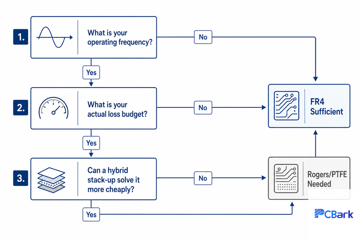
Here’s the honest answer nearly every commercial fabricator page avoids stating plainly: Rogers and PTFE materials aren’t always necessary. Independent industry sources cross-confirm that standard FR4 remains sufficient for a meaningful share of low-to-medium-frequency designs, and at least one published academic comparison found FR4 can be characterized and used successfully in a 5.62 GHz C-band patch antenna design (17.5 dB gain, 5% bandwidth) when loss and bandwidth requirements allow it.
The 3-Question FR4-to-RF Threshold Test
- What’s your operating frequency? Below roughly 1-2 GHz, FR4’s loss tangent (~0.02) rarely dominates your loss budget. Above 5-10 GHz, it typically does.
- What’s your actual loss budget, not just your frequency? A short, low-loss-critical trace at 6 GHz may tolerate FR4; a long run or a receiver-sensitivity-critical path at the same frequency may not. Frequency alone is the wrong single variable – FR4’s loss tangent (~0.02) runs roughly 7-8× higher than RO4003C’s 0.0027, but whether that gap matters depends entirely on your specific insertion-loss allowance.
- Can a hybrid stack-up solve it more cheaply than an all-Rogers board? Mixing FR4 for digital/power layers with a Rogers-class material only on the RF layer is a well-established way to hold RF performance while cutting material cost – industry practice puts the savings at roughly 30-40% versus an all-Rogers stack-up, with minimal RF performance penalty when the transition is designed correctly.
Rogers’ own published datasheet values make the trade-off concrete: RO4003C’s loss tangent of 0.0027 at 10 GHz runs roughly 7-8× lower than FR4’s commonly cited 0.02 (exact FR4 loss tangent varies by manufacturer and grade), while costing roughly 3-4× more per panel – a real engineering trade-off, not a case where one material is simply “better” in every scenario. Don’t let a supplier upsell you into full-board Rogers construction when your loss budget, not your marketing brief, is what should be deciding the material.
Designing for Controlled Impedance on RF Substrates
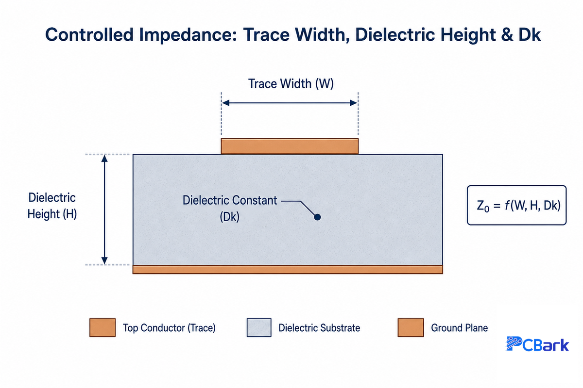
Choosing the right dielectric only gets you half the way to a working RF design – trace geometry and copper quality determine whether that dielectric’s Dk actually delivers the impedance and loss performance its datasheet promises.
The characteristic impedance of a microstrip trace is given by Z0 = √(L/C), where the trace’s inductance and capacitance per unit length is determined by trace width, dielectric height, and Dk. For instance, a practical example: for a 5 GHz microstrip with about 1 Ω/cm conductor resistance and Z0 = 75.3 Ω, the conductor-loss attenuation is approximately 0.664 Np/m — as you can see impedance and loss are related, not independent variables that can be adjusted individually.
📐 Engineering Note
Copper surface roughness reduces the effective loss due to its effects on skin depth, an effect captured by the Hammerstad-Jensen correction factor Kr = 1 + (2/π)·atan(1.4·(Δ/δ)²), where Δ is the RMS copper roughness and δ is the skin depth at the operating frequency. As frequency increases, skin depth becomes smaller and the effect of copper roughness more pronounced. Roughness-driven increases in insertion loss of 25-45% are often seen at mmWave for particular geometries. Specify low-roughness (reverse-treated or very-low-profile) copper foil for everything above 24 GHz; don’t assume standard electrodeposited copper is going to give you datasheet performance.
“If you aren’t paying for controlled impedance, you aren’t getting controlled impedance boards.”
RF design engineer, r/rfelectronics community discussion
This statement reflects a real issue with how controlled impedance is treated in the real world; it’s an explicit feature that the designer must request, define, and test for (not just rely on an estimate from a simulation), not a built-in characteristic of a standard board quote. Before you proceed with a production run, make sure your fab house has some method of verifying a controlled impedance PCB against its target, preferably via TDR testing on production test coupons rather than relying on simulation alone. If you use PCBark, you’ll catch potential impedance problems in our DFM analysis service prior to beginning fabrication.
How Rogers and PTFE PCBs Are Actually Fabricated
Specialized materials have special process requirements. Beyond simply the raw material cost, RF substrate boards cost more mainly because RF substrates aren’t just processed like standard FR4 in an off-the-shelf fabrication line; they’ve different requirements, especially the PTFE-based ones, at almost every step of the way.
Copper adhesion to PTFE is challenging. PTFE is notoriously inert; the very reason it offers such good performance with low loss and low moisture absorption is its reluctance to participate in chemical reactions. Research in materials science has shown that heat-assisted plasma treatment coupled with thermal compression can provide a strong adhesive-free bond between copper and PTFE, and that low-power plasma treatment of PTFE improves copper-to-PTFE adhesion without the surface roughness that would otherwise increase the signal loss of the board. What this means in practice is that PTFE boards require a plasma or chemical-etch pretreatment step that a standard FR4 fabrication process doesn’t include.
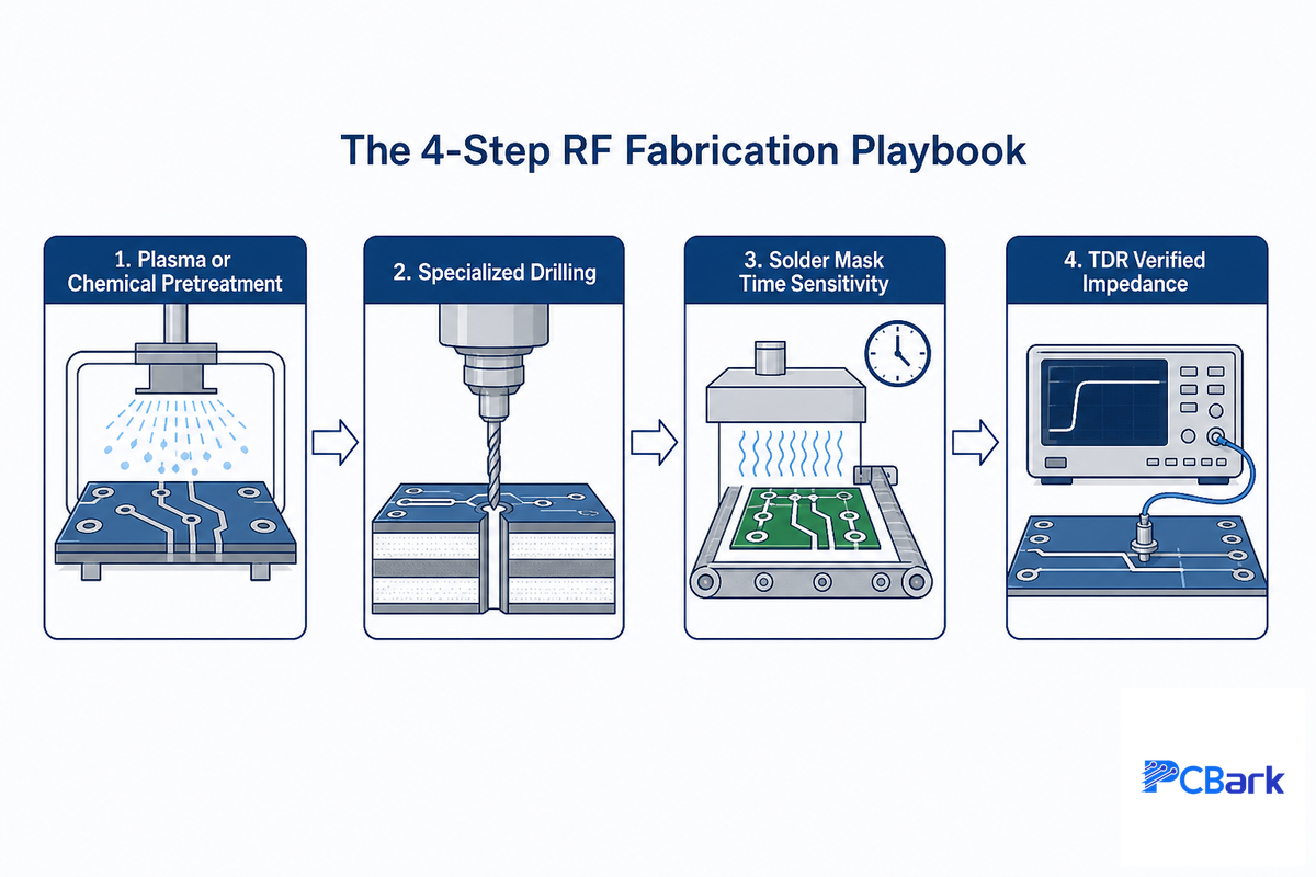
The 4-Step RF Fabrication Playbook
- Plasma or chemical pretreatment. Activates the PTFE surface chemically so the copper foil can stick, instead of relying on a mechanical “keying” into a rough surface that will harm the signal performance.
- Specialized drilling. Because PTFE is softer than FR4, drilling requires lower in-feed rates and higher chip loads to prevent smearing or delamination at the hole wall.
- Solder mask time sensitivity – Ceramic filled PTFE materials have a short time window in which they reliably adhere (most cited at 12 hours of previous process step) before surface energy changes diminish that bond.
- TDR verified impedance – the last test check described in the previous section, performed on production test coupons as opposed to assumed via simulation.
Handling discipline counts all the way through – RF substrate material is more moisture-sensitive and physically fragile than FR4 in between process steps, and delamination is increasingly possible if the lamination profile is generic for an FR4 substrate, rather than specifically set for the cure profile of the material you’ve selected. This is also where PCB fabrication capability will begin to be more important than material choice alone – please refer to PCBark’s general RF and high-frequency PCB manufacturing expertise, our quick-turn prototyping through full production, and our range of RF substrate material solutions for the scalability of these processes with frequency, and to our quality certifications to confirm the standards on which our fabrication process has been qualified.
Qualification and Reliability Testing for RF Substrates
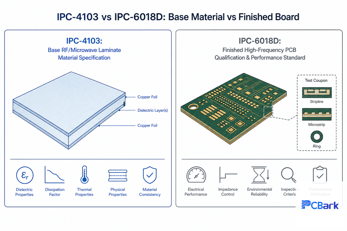
Two thirds of competitor guides that we review on the subject matter skip any reference to reliability and qualification almost entirely, which is a considerable risk and coverage gap given there are two IPC standards dedicated specifically to validating performance and reliability of the finished board, and neither is optional if your RF PCB design program is going to be defended by a supplier with significant technical chops.
IPC-4103 covers the base material itself – the raw laminate specifications for electrical performance, thermal properties and physical dimensions, which are distinct from the IPC-4101 standard that applies to FR4 equivalent materials. IPC-6018D is the companion to IPC-4103 and the one most frequently omitted from competitor content – it addresses the qualification and performance standards that must be met by a final high-frequency / microwave printed circuit board and addresses electrical and mechanical stress, thermal shock and standard test coupons. Together, IPC-4103 defines if you’ve the right base material; IPC-6018D defines if your completed PCB performs the way you want it to.
What Are PCB Test Coupons?
A test coupon is an intentionally over-engineered miniature pattern of the circuit that will appear on the actual PCB, constructed from the same copper thickness, raw materials, and processes used to build the main panel. Rather than trying to inspect the real PCB for features such as plated through-hole dimensions, the fabricator processes the entire panel through the full build cycle and then deconstructs the test coupon instead.
TDR impedance checks, as mentioned previously, are typically made on these coupons, as are any number of tests for plated through-hole dimensions or cross-sectional integrity. IPC-6018D has standard test coupons, specifically designed for high-frequency, so it’s important to find out from your manufacturer if their coupon is made to IPC-6018D standards or an equivalent internal method.
The dielectric constant itself can be measured with one of two common methods – clamped stripline resonator testing, as per IPC-TM-650 2.5.5.5, or split-post dielectric resonator testing, both of which have a process for determining process Dk (as-built Dk) as separate from design Dk (as used for simulation with recommendations by Rogers). For example, an RO4003C substrate has a process Dk of 3.38 and a design Dk of 3.55 – a value that it’s certainly worth corroborating with your fabricator before settling your circuit simulation designs on a particular stack-up. PCBark’s inspection capability covers both TDR impedance verification and dimensional/material conformance checks against these standards.
Where RF Substrates Are Used: Applications by Grade
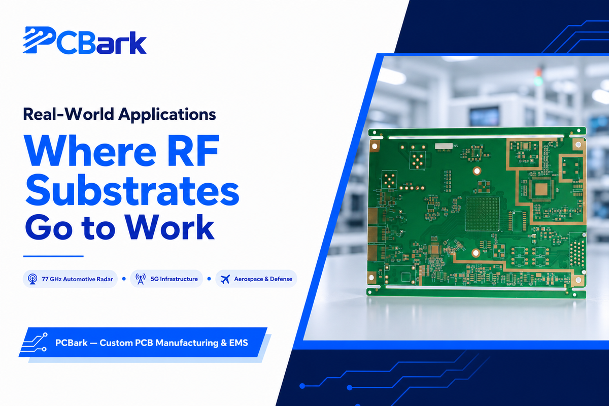
Application requirements map pretty cleanly to the grade taxonomy above. RO4000-series ceramic-filled hydrocarbon materials are deployed on the majority of applications – 5G wireless communication infrastructure, Wi-Fi 6E access points, and GNSS receivers – because their cost premium over FR4 is minimal compared to the gains in RF performance.
Rogers’ RO3000-series ceramic-filled PTFE grades, prized for a low dielectric constant paired with tighter Dk stability, come into play when lower loss justifies a greater cost premium, a situation commonly found in multilayered design where several distinct dielectric constants are used across a stack-up.
Pure PTFE materials, such as RT/duroid 5880, are found at the very top of performance requirements – for 76-81 GHz automotive radar (where the loss impact of copper surface roughness and insertion loss, discussed earlier, is highest), for satellite E-band backhaul, and for aerospace/defense applications where outgassing and a low coefficient of thermal expansion (CTE) for dimensional stability at thermal cycling conditions are equally important as RF loss. Further evidence of the suitability of pure-PTFE materials for high frequency and loss-critical applications can be found in recent academic work investigating flexible RF substrates for frequencies > 100 GHz, a very active area of research.
As a specific data point to illustrate, a graduate student at the University of Arkansas used Rogers RO4350B as the standard substrate material for the test board (an ambient temperature board) of a gallium nitride power amplifier – this provides a tangible example of the research community’s preference for RO4350B over more exotic substrate materials and highlights its status as a leading commercial product. PCBark produces RF substrate boards for many of the end markets discussed here including aerospace and automotive radar applications.
Ceramic PCB: An Alternative High-Frequency Substrate Worth Knowing
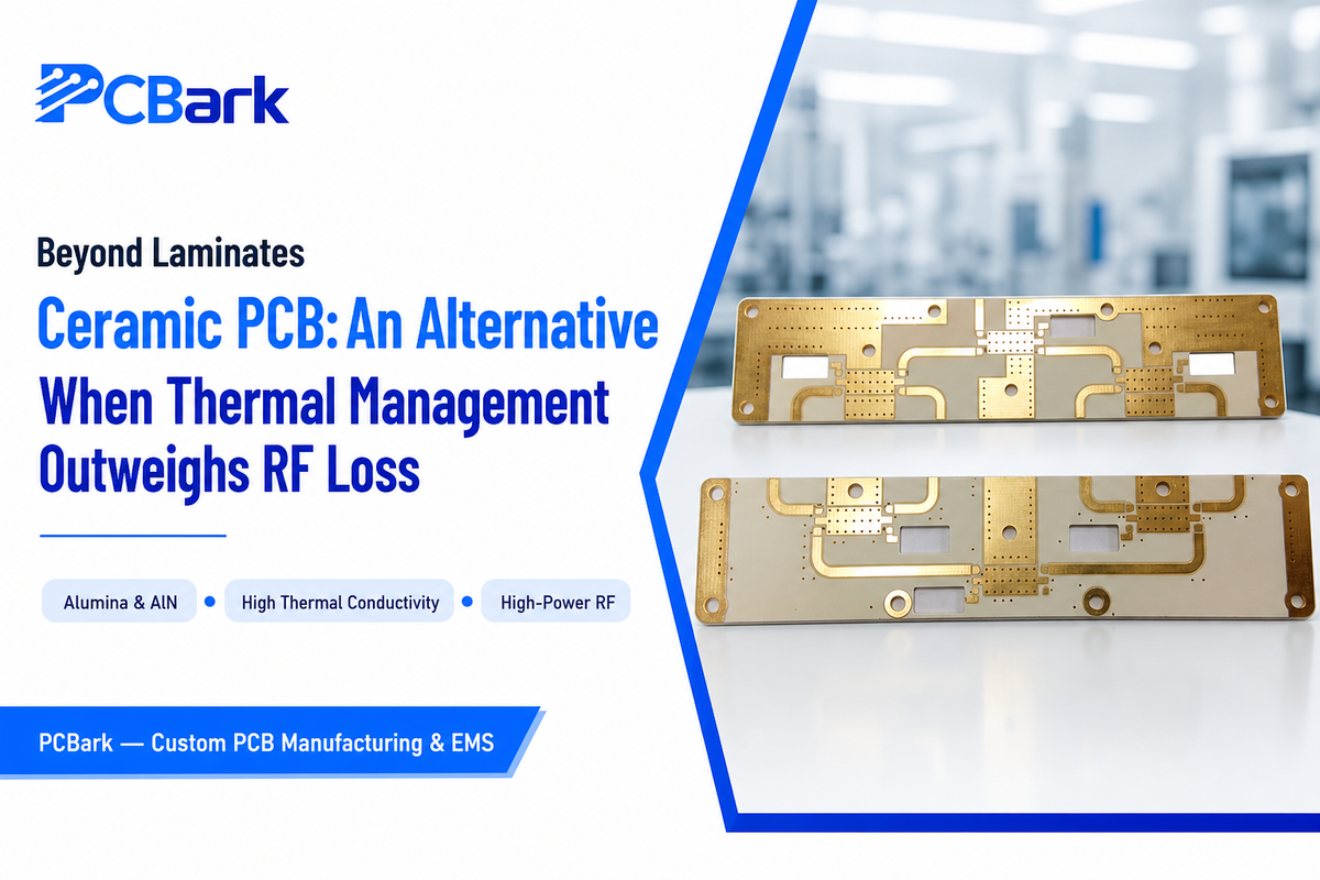
PTFE laminates, however, aren’t the only available high-frequency substrate materials. Ceramic-based PCB systems, including alumina, aluminum nitride and other technical ceramic-based materials offer improved thermal management capability over laminates at the cost of a reduction in the available options to tailor design to specific dielectric requirements, making ceramic PCBs a good choice for applications limited by heat generated by high-power RF amplifiers rather than solely dielectric loss. In many extreme millimeter wave applications it may be necessary to go further and use alumina, sapphire or quartz substrates and specialised transmission line designs. This guide’s focus stays on laminate materials, but if thermal management is your primary constraint rather than RF loss, see PCBark’s ceramic PCB capability page or our ceramic PCB materials guide for a full comparison.
RF Substrate Industry Outlook: What’s Changing in 2026
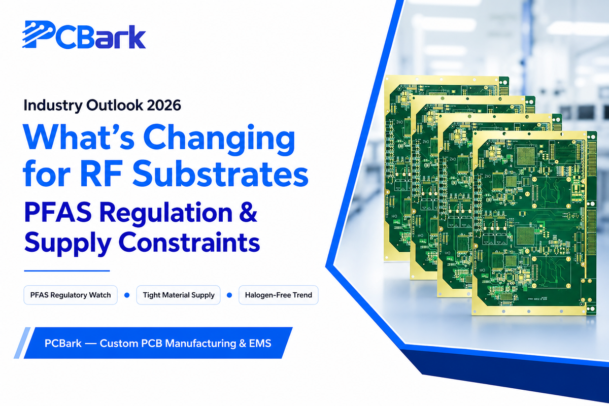
What’s going to have the biggest near-term impact on buyers of RF substrates? No new material, but instead a regulatory push on the fluorinated chemistry underpinning the material in the first place – that’s the critical concern here. Pure-PTFE and ceramic-filled PTFE RF substrates, which many engineers have been leaning on for years, contain this chemical class. As of 2025, electronics and semiconductor manufacturing are officially identified as major users of PFAS class of chemicals, and PTFE material use in particular has been singled out in the European regulatory context. This places any designs relying on RT/duroid or the RO3000-series of materials right in the cross-hairs of this emerging regulatory discussion and compliance issue. Make sure that, going forward, your material suppliers are providing detailed, updated tracking on PFAS related regulations impacting your markets. Otherwise you may encounter sourcing issues just when you need the most support.
Adding to the concern, there’s already a tight supply for these high-end materials, with supply-demand imbalances expected to continue at 20 percent and above through 2026. Many PCB manufacturers, particularly those specializing in Rogers PCB material, have recently announced major capacity expansions for their laminates production in early 2026. This suggests the wait time for Rogers-class materials might not decrease any time soon. Increasing demand for data center infrastructure and AI interconnects may be partially responsible, though these are more general capacity issues than those directly affecting the specific demand drivers for RF substrates. It’s also worth monitoring the trend toward halogen-free material formulations that continues to gain attention throughout the industry, a second, distinct, regulatory trend related to environmental concerns. if you’re working with an RF program for 2026, discuss with your fabricator their plans and their perspective on both lead times and compliance related to materials.
Frequently Asked Questions
Q: What is the difference between Rogers and FR-4?
View Answer
Standard FR-4, with a dielectric loss tangent around 0.02, offers acceptable performance for digital and low-frequency signals, but this loss becomes too high for RF and microwave use. Rogers materials replace the dielectric with ceramic-filled hydrocarbon or PTFE systems, cutting loss tangent by an order of magnitude at roughly three to eight times the cost.
Q: What is Rogers PCB material?
View Answer
Rogers PCB material is a broad category spanning ceramic-filled hydrocarbon, ceramic-filled PTFE, and pure PTFE laminates manufactured by Rogers Corporation, all engineered for stable dielectric constant and low signal loss above roughly 1-2 GHz. Which specific laminate counts as the right Rogers PCB material for your design depends on target frequency, loss budget, and whether RF and digital circuitry share the same substrate.
Q: What does the Rogers company do?
View Answer
Based in Chandler, Arizona, Rogers Corporation designs and manufactures engineered materials, such as laminates, bond plies, and prepregs, for high-frequency circuit boards and other electronics applications. PCB fabricators, including PCBark, convert these materials into finished circuit boards; Rogers itself does not manufacture boards, worth knowing when a datasheet references “Rogers” rather than the board manufacturer.
Q: Why use Rogers printed circuit boards instead of standard FR4?
View Answer
Rogers or PTFE beats FR4 above a few GHz on three fronts: a lower, more stable Dk for tighter impedance control, roughly ten times lower loss tangent, and better thermal stability under RF-amplifier power densities. None of that matters for a low-frequency digital board.
That’s why working out the FR4 threshold from earlier in this guide matters more than picking a substrate because it *sounds* advanced on the spec sheet. If you’re unsure which side of that threshold your design lands on, ask your fabricator to walk through the loss-budget math with you before locking in a material spec.
Q: What are Rogers RO4000 PCB materials?
View Answer
The RO4000 series is Rogers’ ceramic-filled hydrocarbon laminate family, including RO4003C, a widely specified high-frequency laminate grade, and RO4350B, both processed on much the same equipment as standard FR4 boards. It’s Rogers’ most specified grade family for commercial microwave and high-speed applications.
Q: Is Rogers material the same as PTFE?
View Answer
No – only some Rogers material is PTFE. RT/duroid and RO3000-series products are either pure PTFE or a composite of PTFE and ceramics. But the RO4000 series (the Rogers grade most often specified for commercial applications) is a ceramic-filled hydrocarbon thermoset without PTFE. Assuming “Rogers” always equates to “PTFE” leads to mismatched fabrication expectations: PTFE-based grades need specialty plasma treatment and drilling, while RO4000-series hydrocarbon materials process on largely standard FR4-style equipment, worth confirming before finalizing a stack-up.
Ready for an actual quote?
Why We Write This
PCBark fabricates Rogers, PTFE, and ceramic-filled RF substrate PCBs across our 500,000 sqm/yr production capacity, built over 16+ years of turnkey EMS manufacturing. We built this resource because when researching for our own product design, most material information-even from larger suppliers-rehashed similar data with little justification or link to datasheets. We believe customers deserve to understand the physics of why they’re selecting a grade over others, rather than trusting a datasheet designation. Reviewed by the PCBark technical team.
References & Sources
- RO4003C Laminates Datasheet — Rogers Corporation
- TSL-1 Non-Government Standards Adopted (IPC-4103 listing) — U.S. Department of Energy
- IPC-6018D: Qualification and Performance Specification for High-Frequency (Microwave) Printed Boards — IPC
- All About IPC-4101 and IPC-4103 Slash Sheets — Altium
- Design and Testing of a Gallium Nitride Power Amplifier for High-Temperature Applications — University of Arkansas ScholarWorks
- Direct Adhesion Between Cu Foil and Polytetrafluoroethylene Without Adhesive — PMC / National Institutes of Health
- Process to Improve the Adherences of Copper to a PTFE Plate — Advances in Materials Science and Engineering
- Microstrip (Hammerstad-Jensen surface-roughness correction) — Wikipedia
- US12512232B2: Low Loss Tangent Dielectric Based on Spinel-Structured Oxide — USPTO / Google Patents
- C-Band Microstrip Patch Antenna on FR4 Substrate — arXiv
- PFAS Use in Electronics and Semiconductor Manufacturing — arXiv
Related Articles
- Ceramic PCB Materials Guide — when ceramic substrates outperform laminate-based RF materials
- About PCBark — 16+ years of turnkey EMS manufacturing