
Get in touch with PCBark Company


![Drone PCB Design Guide: IPC Class & Manufacturing [2026]](https://pcbark.com/wp-content/uploads/2026/07/drone-pcb-design-guide-featured.png)
Drone PCB is the printed circuit board that unifies a drone’s flight controller, motor drivers, and power distribution into a single weight-constrained assembly, built to survive continuous vibration and stay electrically quiet next to its own control and video links.
Quick Specs
| Typical layer count | 4 (standalone flight controller), 6 (integrated ESC), 8 (all-in-one with VTX + PDB) |
| Common substrates | Standard FR4, Rogers RF laminates (antenna sections), polyimide rigid-flex (foldable arms) |
| Reliability class range | IPC-A-610 Class 2 (commercial/consumer) through Class 3 (logistics/defense-adjacent) |
| Current-carrying reference | IPC-2152 (modern) alongside legacy IPC-2221 charts |
| Regulatory touchpoints | FAA Part 107 (sUAS <55 lb), DO-160G environmental qualification (avionics-grade programs only) |
It embodies every requirement of a normal embedded electronics board, plus three that, to the best of my knowledge, no other commercial board encounters simultaneously. Given a typical airframe weight between 250g and 2kg running an 11.1-22.2V (3S-6S) battery, the board has to stay light enough to fly, tough enough to survive motor vibration that never ceases, and electrically quiet enough not to disrupt the 2.4GHz control link and 5.8GHz video link a few millimetres from those current-hungry switching traces. Solve only one of these challenges, and the result is an un-flyable board, a premature failure, or a dropped control/video link.
A drone PCB — also called a drone circuit board, or simply a PCB for drones — is the printed circuit board that mechanically and electrically couples together a drone’s flight controller, motor drivers, power distribution, and sensor and radio subsystems. Unlike a stationary IoT board, it has to simultaneously minimize weight, resist continuous vibration, dissipate motor-driver heat, and preserve GPS and control-link signal integrity, four constraints that amplify each other rather than trading off cleanly.
What a Drone PCB Actually Has to Survive
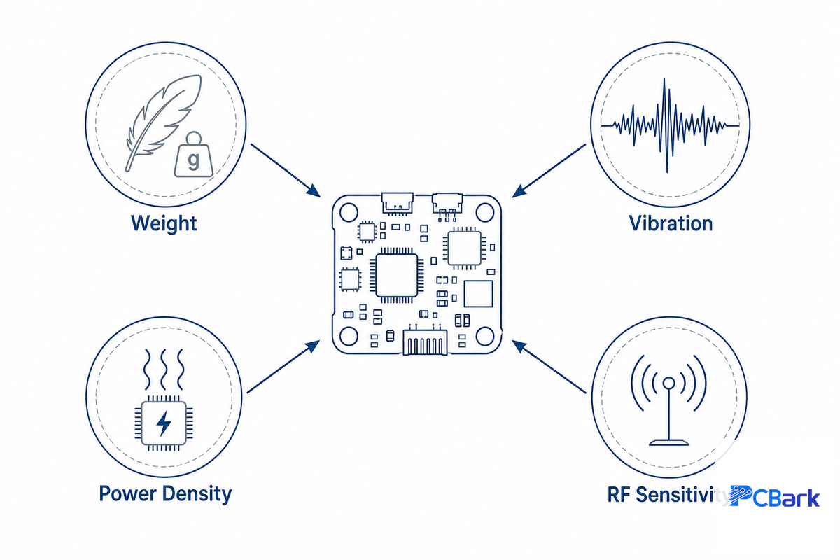
A drone PCB has to survive four constraints landing on the board simultaneously: strict weight limits, continuous motor vibration, concentrated power density from motor drivers, and RF sensitivity from low-power control and video links sharing the same small board. Every later material choice, layer-count choice, and reliability-class decision in this guide traces back to one or more of these four pressures, listed below:
- Weight – for each gram of copper, substrate or connector removed, you can extend flight time or increase payload accordingly.
- Vibration — brushless motors and propeller imbalance generate constant, broad-spectrum mechanical stress across the airframe, not an occasional impulse.
- Power density — motor drivers are capable of pushing tens of amps through a board which must remain cool to the touch, without fans.
- RF sensitivity — video and telemetry links are very low-power receivers sharing space on the board with the noisiest circuits.
None of these are drones-specific: vibration resistance is used in auto electronics, RF isolation on mixed signal boards is a given. What’s less common is all four applied to a few square inches of board with an unforgiving weight constraint. In practice, a board that satisfies three of the four and skips one still fails: a light, quiet board that overheats mid-flight is just as grounded as a well-cooled board that drops its video link. That’s where a drone electronics project requires consideration of the PCB specification at a programmatic level, rather than the simple check-list approach (“follow best practices”) described in the 9-Profile Drone Duty-Class Matrix presented below. These same reliability principles — solder-joint integrity under sustained vibration and clean signal isolation — are exactly what NASA’s own electronic-assembly workmanship standards (NASA EEE Parts and Packaging Program) were written to enforce, just at a smaller physical scale.
Core Components: Flight Controller, IMU, ESC, and Power Distribution
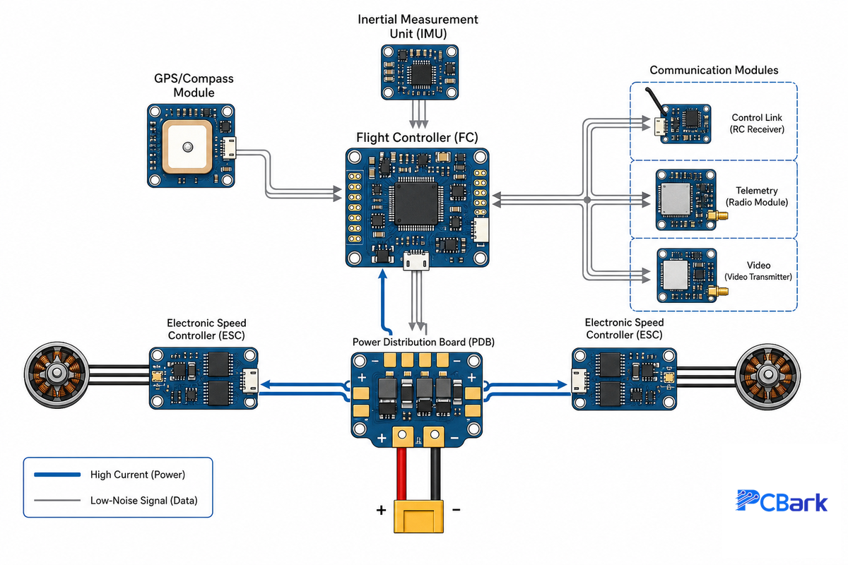
A drone electronics stack is decomposed into several functional building blocks, each responsible for the driving of a particular downstream layout and spec choice. The soldering and inspection criteria that ultimately qualify these subsystems trace back to the same IPC soldered-assembly requirements NASA JPL catalogs for its own flight hardware. Whether you call it the main board or the control board, this is where analog sensor lines, digital control signals, and switching power all have to coexist on a single multilayer PCB — which is also why the bill of materials (BOM) and where you place components on the board matter as much as the schematic itself.
| Subsystem | Function | Design impact |
|---|---|---|
| Flight controller (FC) | A microcontroller (MCU) that runs stabilization algorithms and outputs motor commands hundreds of times per second, exposed to the outside world through a USB port for firmware flashing and configuration | Needs a quiet, low-noise power rail and short, matched traces to its IMU |
| Inertial measurement unit (IMU) | Combines a gyroscope and accelerometer to sense orientation, angular rate, and acceleration for flight stability | Must sit away from motor current paths and switching regulators, ideally near the center of mass |
| Electronic speed controller (ESC) | Converts FC commands into three-phase drive signals for brushless motors | Carries the highest current on the board; drives copper weight and thermal design |
| Power distribution board (PDB) | Handles power management by splitting battery voltage into regulated power supplies for FC, peripherals, and video | Needs separate power domains to stop motor noise from coupling into logic rails |
| GPS / compass module | Provides position and heading for autonomous flight and return-to-home | Extremely sensitive to EMI; usually isolated on a mast or external module |
| Communication modules (control link, telemetry, video transmission) | 2.4 GHz / 5.8 GHz control, telemetry, and FPV video links | Requires controlled-impedance antenna traces; range drops sharply with poor matching |
What’s the Best PCB Layer Count for a Drone Flight Controller?
The best layer count depends on integration level: a stand-alone flight controller (FC plus sensors, with ESCs on separate boards) usually gets by with 4 layers; putting the ESCs on the same PCB pushes that to 6 layers minimum; and full all-in-one designs that also fold in a video transmitter and the entire power distribution typically need 8 layers. Layer count is fundamentally a routing and thermal decision, not a cost-cutting lever.
A 4-layer stack uses top and bottom signal layers sandwiching an internal ground and power plane, which keeps the FC’s ground plane clean for the IMU’s SPI bus and the RF receiver without extra cost. The jump to 6 layers is driven by the need for additional internal layers carrying high-current motor phases without disturbing the power plane located beneath signal traces. Going to fewer layers to cut fabrication cost on an integrated design just pushes the same problem into power plane splits and RF noise instead.
Most flight controllers can operate on an open-source firmware stack (Betaflight, ArduPilot, etc.) as opposed to fully proprietary. The main implication of that for drone PCB design is that the firmware imposes an expectation of a specific pinout and peripheral assignment set, and you need to be aware of which particular UART, I2C, and SPI assignments you can count on when finalizing your connector layout. Hobbyist development boards built around KiCad or similar PCB design software, using an ESP32 or similar microcontroller, are a reasonable way to prototype this pinout on the bench, but an ESP32-based drone build and a certified commercial flight controller are solving genuinely different problems — one optimizes for DIY drone accessibility, the other for repeatable manufacturing at volume.
Design Constraints That Actually Break Drone Boards
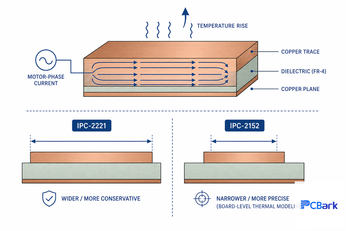
The most common failure mechanisms on the field-running drone pcb that have occurred so far can be categorized into three broad groups: inadequately sized traces carrying current; vibration-induced failure of solder joints; and RF noise coupled from the power circuitry into the receiver circuit.
📐 Engineering Note — sizing a motor-phase trace
Take a 15A motor-phase current on an external (outer-layer) trace, targeting a conservative 10°C temperature rise. Using the classic IPC-2221 formula for external conductorsI = k × ΔT0.44 × A0.725, with k = 0.048, solving for cross-sectional area A gives roughly 685 mil². On 1 oz copper (1.378 mils thick) that works out to about 500 mils (12.7mm) of trace width, wide enough that most drone power sections instead specify 2 oz copper, which cuts the same 685 mil² requirement down to roughly 250 mils (6.35mm), a far more layout-realistic width for a compact ESC section.
This result for a motor-driver trace is quite conservative because the underlying IPC-2221 current capacity formula was derived for a single-trace model. The IPC-2152 spec is the more modern standard for this type of current capacity calculation; it explicitly models board-level thermal spreading, proximity of planes, and multiple adjacent traces — Purdue University’s independent trace-temperature correlation study and a Cal Poly thesis both work through this exact analysis for a three-phase motor controller, rather than the simplistic model used by IPC-2221 tables. IPC-2152 is now often cited for this calculation in design work, although the legacy IPC-2221 standard is still used out of habit for much general-purpose drone-PCB advice, so it’s useful to ask which standard the fab house is using for their DFM analysis.
The second failure mode, vibration, is pervasive rather than intermittent. drone motors impart broadband mechanical vibration spanning roughly 10 Hz to several kHz as a function of their rotational velocity and prop balance; this vibration is constant rather than an intermittent shock. Over time, this stress causes high mass components (BGAs, power connectors, shielded RF modules) to suffer fatigue failure at their solder joints. These failures can happen long before the board material itself fatigues. Mitigation techniques are standard practices from the aerospace and automotive electronics industry: heavy components need mechanical fastening (stakes or bonds) in addition to solder to keep them secured; IMUs need to be isolated from the main sources of vibration; and vibration testing needs to be conducted with actual flight load profiles, not single-frequency tests.
Third is RF interference, which almost always turns out to be a layout, not component, issue – typically an issue caused by an adjacent high-current switching trace that’s coupled into a GPS or telemetry receiver either through a shared power plane, a radiated emission off of an unshielded trace, or by an interrupted ground plane return path below a controlled impedance signal. The easiest ways to mitigate this prior to any EMC testing are to partition RF circuitry to its own ground region, to keep the antenna traces clear of any plane splits below them, and to add filtering to any power rail feeding sensitive receivers. Most of what shows up as unexplained electromagnetic interference in the field traces back to one of these three root causes, not a mysterious high-speed signal integrity problem, and heat dissipation from nearby switching regulators only makes the coupling worse.
Material Selection: FR4, Rogers, Rigid-Flex, and When Each Wins

| Application | Recommended material | Why |
|---|---|---|
| General flight controller / ESC | Standard FR4 (Tg 130-140°C) | Lowest cost, adequate for typical operating temperatures |
| Integrated ESC / high-power video transmitter | High-Tg FR4 (170°C+) | Resists warping and delamination under sustained reflow and operating heat |
| GPS / long-range antenna, high-power VTX | Rogers or similar RF laminate (hybrid stack-up with FR4) | Lower and more stable dielectric loss keeps antenna tuning consistent across temperature |
| Foldable arms, gimbal interconnects, space-constrained frames | Polyimide rigid-flex | Eliminates connectors across a moving joint, reducing weight and failure points |
The primary reason for sticking with FR4 by default is almost invariably cost: high-end RF grade laminates (Rogers, etc) generally cost 3-8X the per-panel material of standard FR4, and rigid-flex builds carry a roughly similar 3-8X cost premium over rigid equivalents. This range holds consistently across different independent fabricators, so it should be part of your drone PCB board price planning (although precise multipliers can vary depending on panel size, layer count, board thickness, and volume). This premium can easily be justified on a localized portion that absolutely needs it (a folding arm or a section of an antenna trace) and difficult to justify on a whole panel. For most designs that use Rogers and/or rigid-flex, this translates into a hybrid stack-up where only the necessary portions of the board use specialty material. Rigid-flex design constraints and bend radius calculations are handled elsewhere and I don’t have space to fully discuss them here; the bottom line takeaway for a drone project is that rigid-flex provides its benefit on a hinged joint, not on an airframe basis.
IPC Class 2 vs Class 3, Choosing the Right Reliability Tier
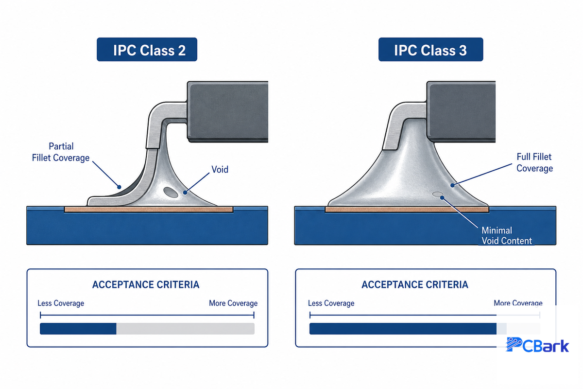
The one constant across almost every drone pcb guide is the passing reference to IPC Class 2 vs. Class 3 — most fail to explain the on-the-field implications of this choice for a drone design, which is precisely what this section aims to fix.
IPC-A-610, “Acceptability of Electronic Assemblies” — also cataloged by NASA’s Jet Propulsion Laboratory as a reference standard for soldered assemblies (Revision J was the current edition as I wrote this, but there’s periodic updates to check with your standards library or EMS provider before quoting it) — outlines the criteria by which a finished assembly is inspected. The core of the difference between IPC Class 2 and Class 3 is the degree to which the standard allows variation (cosmetic or minor workmanship) before declaring a connection to be out of compliance. Multiple sources have converged to give a fairly consistent picture of the differences in acceptance criteria: Class 2 requires that a significant portion of the joint surface of a lead is covered by solder (often approximated as >50% coverage of the lead’s thickness, and about 75% side fillet on surface mount connections), whereas Class 3 requirements raise this to 100% of the connection area, and tighten the allowable void content in a BGA package to ~9% (exact values depend on the connection geometry and specific component). Additionally, while Class 2 allows a small amount of “breakout” (where a lead extends beyond the expected annular ring at a plated-through-hole), Class 3 requires that this be completely eliminated.
“The right answer is the class that matches your product’s criticality, operating environment, and regulatory context, no more, no less.”
| Drone program type | Recommended IPC class | Why |
|---|---|---|
| Consumer / hobbyist FPV, racing (quadcopter) | Class 2 | Failure is a crashed airframe, not a safety or mission-critical event |
| Agricultural spraying, mapping/survey | Class 2 (Class 3 if flying scheduled commercial routes over people) | Extended duty cycle and outdoor exposure argue for Class 2 at minimum; regulatory exposure can push higher |
| Industrial inspection (utility lines, flare stacks, confined spaces) | Class 2, moving toward Class 3 for BVLOS programs | Mission failure has a real cost, though not typically a safety-of-life one |
| Logistics / delivery, sustained BVLOS operation | Class 3 | Continuous scheduled operation over people and property raises the consequence of an in-flight electronics failure |
| Defense-adjacent / ISR | Class 3, plus program-specific qualification | Mission failure and, in defense programs, regulatory export-control obligations both apply — see the compliance boundary below |
📐 Engineering Note
Class 3 isn’t free, the tighter inspection, lower placement speeds and increased rework/scrap required for a Class 3 board commonly adds approximately 15-30% to the per unit cost vs. a similar Class 2 build. Specifying Class 3 for a hobbyist FPV board buys that premium for reliability margin the application never uses. Specifying Class 2 for a BVLOS logistics program saves that premium and keep it exactly where a field failure is most expensive to explain. PCBark builds to both IPC Class 2 and Class 3 so it’s a program fit conversation, not a capability limitation.
Regulatory and Environmental Qualification Context
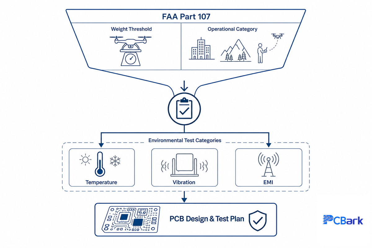
Two regulatory reference points are germane to a commercial drone electronics program and neither is an optional detail — both dictate which reliability tier and which environmental validation the program needs.
In the United States, the FAA’s Part 107 rule governs small unmanned aircraft systems (sUAS) — the regulatory term for the class of unmanned aerial vehicles (UAVs) most commercial drone programs fall into — which is defined as an aircraft with a maximum take-off weight of less than 55 lbs. That weight threshold defines sUAS eligibility – it doesn’t mean free flight over anything – under Part 107 you still need a Remote Pilot Certificate, drone registration, and adherence to Part 107 rules (visual line of sight is the default, with FAA authorization required to operate in controlled airspace and a separate process for night operation or flight over people). Still, it’s the regulatory operational category that nearly every commercial drone pcb program discussed in this guide is designed for — full aviation regulation, that’s Parts 25 and beyond with DO-178 / DO-254 software and hardware assurance; that regime applies to certified aircraft, not the sUAS that most drone electronics programs will be based on.
When environmental qualification comes into play the reference shifts to DO-160 “Environmental Conditions and Test Procedures for Airborne Equipment.” The G revision (2010) of DO-160 is the current version for a decade, it’s cited by Advisory Circular AC 21-16G from the FAA. RTCA’s SC-135 committee is currently developing a DO-160H which is anticipated for 2026 publication – check with RTCA or your test house before entering this in your contract as it’s subject to revision delays. DO-160 sets a standard of specific test categories for temperature, vibration, EMI that certified avionics must meet – it’s a very good engineering framework for developing a drone environmental test plan even if full DO-160 certification isn’t the goal since sUAS electronics aren’t required to hold DO-160 certification like certified avionics for aircraft are. Adopting relevant test categories (temperature cycling, vibration, EMI/EMC) for your program is a very practical middle-road approach that results in a strong validation plan without the full expense of avionics certification.
Honest capability boundary
PCBark’s drone pcb programs are built for commercial and civil use – agricultural, industrial inspection, logistics and consumer / prosumer aircraft. PCBark isn’t an aerospace quality AS9100 registered company, nor are we ITAR registered. Thus, if your drone electronics program is under defense control or ITAR regulations, PCBark isn’t a suitable fit. This boundary is consistent with our approach to our aerospace PCB work.
The 9-Profile Drone Duty-Class Matrix
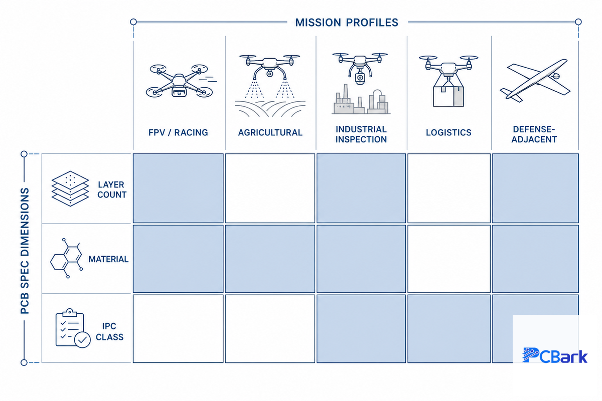
Consolidate the material, IPC class and layer count choices made above into one resource that will help match your program to a PCB spec: A drone mission profile is the fastest route to a reasonable starting point spec before a DFM review.
| Mission profile | Layer count | Material | IPC class | Conformal coating |
|---|---|---|---|---|
| FPV / racing (recreational) | 4 | Standard FR4 | Class 2 | Optional |
| FPV / racing (competitive circuit) | 4 | High-Tg FR4 | Class 2 | Recommended (frequent hard-landing exposure) |
| Agricultural spraying | 6 | High-Tg FR4 | Class 2 | Required (moisture, chemical exposure) |
| Agricultural mapping / survey | 6 | High-Tg FR4 | Class 2 | Required (dust, humidity) |
| Industrial inspection (visual / thermal, line-of-sight) | 6 | High-Tg FR4, hybrid RF for long-range links | Class 2 | Required |
| Industrial inspection (scheduled BVLOS) | 6 | High-Tg FR4, hybrid RF for long-range links | Class 3 | Required |
| Logistics / delivery (short-range) | 8 (AIO) | High-Tg FR4 + rigid-flex interconnects | Class 2 | Required |
| Logistics / delivery (scheduled BVLOS over people) | 8 (AIO) | High-Tg FR4 + rigid-flex interconnects | Class 3 | Required |
| Defense-adjacent / ISR | 8+ | High-Tg FR4 + Rogers RF sections | Class 3 + program-specific qualification | Required |
Treat this as the start of an RFQ discussion rather than a replacement for a DFM review – unusual payload, altitude or duty-cycle constraints may easily push a program up or down a row. What it replaces is walking into a manufacturer meeting armed with only a layer count and no rationales behind your choices for the class and materials used. PCBark’s drone PCB manufacturing services use this as the basis for an initial spec for customers entering prototype, prior to the DFM step.
Manufacturing, Assembly, and Quality Control

PCB assembly for drones follows the same fabrication and assembly pipeline as any multilayer board, with a few drone-specific checkpoints layered on top.
Drone PCB assembly follows the same basic steps as a multilayer board: inner-layer imaging and etch, lamination, drilling, copper plating, outer-layer process, solder mask, surface finish, silkscreen, singulation. But on a drone, two steps take precedence over standard industrial procedures: power-layer copper weight control to ensure meeting the carrying capacity identified above, and via structure if there are any rigid-flex or hybrid stacks (because improper via location on these parts can create a stress concentration during vibration, not just a connection). This is also where design for manufacturability (DFM) review earns its keep — a custom PCB fabrication run built without a DFM pass on switching-regulator placement and voltage regulator thermal relief (commonly running 20-30°C hotter than datasheet nominal under sustained load) tends to surface its manufacturing process problems on the test bench, not on the datasheet.
What QC actually verifies on a drone board
- AOI (Automated Optical Inspection) for misplaced solder and for placement errors before boards are even powered.
- X-ray inspection to ensure BGA and hidden-via solder is void-free, as defined by the IPC void limits above for class 2/3.
- Electrical test to check for continuity and isolation of every board produced, not a sample.
- Vibration (commonly swept across 10-2000 Hz) and thermal cycling (typically -20°C to 60°C) to test the Design Constraints determined above under a realistic mission profile (rather than a simple single sweep or temperature soak).
Request from the manufacturer to provide their DFM processes, including a reflow process profile that reaches up to 245-260°C (typical SAC-alloy solder) for all boards, a materials certification package, typical 50- or 90-ohm differential impedance data (for the RF or USB connections), and the batch’s full traceability information before committing to production, not after a field failure has already occurred.
Traceability is what separates a field failure from a focused lot investigation (a process measured in hours rather than weeks). And it’s a reasonable expectation of any manufacturer running standard AOI and X-ray inspection. Companies moving from prototype into turnkey production assembly with the same manufacturer should also confirm the manufacturer provide both AOI and X-ray as part of their standard offering, and be careful to avoid changing vendors between prototype and volume manufacturing to minimize process variations introduced.
Industry Outlook, What’s Changing in Drone Electronics Programs

Near-term drivers for drone pcb spec will more than likely be regulatory than technical, with the FAA and international bodies moving to restrict operating parameters under which Part 107 drone can fly unsupervised as commercial sUAS usage grows to routine beyond-visual-line-of-sight (BVLOS) and over-people flights. As such, onboard electronics reliability expectations rise even on programs not connected to a defense/aerospace contract. A logistics drone taking scheduled BVLOS routes over people operates under a fundamentally different set of failure-consequence implications than a line-of-sight single-hobbyist operator on the same airframe, and PCB specs need to follow this lead rather than fall behind it. For programs with 2026-2027 product cycles, the IPC Class and environmental validation plan is a spec item that needs review now, not simply a checkpoint during initial certification.
On the drone technology side — which increasingly overlaps with electronics and IoT more broadly — integration trends are coalescing on all-in-one boards (AIO boards) combining flight controller, ESC, and power distribution into single PCBs. Rigid-flex adoption is expanding beyond foldable-arm airframes to gimbal and payload-bay interconnects as designers seek to eliminate connector count without increasing weight. Market-size figures for the larger printed circuit board sector (an estimated low-$80B in 2025, with a reported mid-single digit CAGR through the early 2030s, per multiple market research outfits — exact figures vary by source and methodology) provide context for PCB manufacturing and material capacity shifts, but serve only as background; regulatory and reliability planning remain the more salient portion of this forecast.
Frequently Asked Questions
These FAQs about drone PCB design cover the questions that come up most often once a program moves past the concept stage.
Q: How do I ensure my drone PCB complies with international standards?
View Answer
As always, don’t get lost in general design guides; instead focus on which standards genuinely apply to your product. For nearly any commercial drone electronics, that will be IPC-A-610 (specify class and revision on all RFQ – currently Rev J), IPC-2152 for current-carrying design, and FAA Part 107 (for commercial operations in the US). Always confirm your manufacturer’s certified Revision with them as the acceptance criteria change between versions.
Q: How do I reduce EMI in my drone PCB design?
View Answer
With layout allowing, keep your RF and power traces as far separated as possible and maintain a continuous ground plane under every controlled-impedance trace. Ensure any power rails feeding GPS, telemetry, or video receivers are conditioned with an LC filter or Ferrite bead before noise ever gets to the receivers; most EMI issues on drone PCBs are traceable back to a ground plane split under an antenna trace or a switching regulator trace running near a receiver input — address those with a clean layout before resorting to shields.
Q: How do I design for vibration in drone PCBs?
View Answer
Mechanically secure heavy components — connectors, large capacitors, tall inductors — instead of relying on solder joints alone for structural integrity, and mount the flight controller and IMU on vibration-damping standoffs where the layout allows it. On the board itself, thicker substrates, added copper planes, and mounting-hole placement that avoids the motor’s dominant resonant frequencies all help keep the board’s own resonance out of the vibration range the motors actually generate. Verify the result with a vibration profile built from your actual flight loads, not a single-frequency sine sweep.
Q: Which PCB material should I use for drone GPS antennas?
View Answer
A simple FR4 substrate works well for a passive GPS antenna for a short range, consumer-grade drone. For a commercial product in which predictable position accuracy is important, however, a Rogers family RF laminate provides better stability of the antenna’s tuned frequency across the temperature range encountered by the drone – cool when at altitude and warm at ground level – because its dielectric constant does not change as much as that of FR4 over temperature. Most projects combine the two materials in a hybrid stack-up to keep the cost of a high-performance RF laminate only where it’s needed – on the antenna section – and FR4 everywhere else.
Q: Why does PCB material selection matter this much for drones?
View Answer
Why is the right material important? Because the wrong material will show up as a problem in the field, not as a simple number in the specifications. A board that’s too heavy reduces flight time; a board that lacks adequate thermal margin might cause an ESC to reduce its power output in mid-flight when maximum power is needed. And an antenna section built with the wrong dielectric will reduce its effective range in a way that is observed as a “connectivity problem” but is actually a material defect that’s baked into the primary layer.
Q: How can I improve the thermal management of my drone PCB?
View Answer
Underneath each ESC’s MOSFETs and other high-heat devices, thermal vias help transfer heat to the internal or back copper layers, a feature that can make the single biggest improvement to a drone power section. A tightly spaced grid of small-diameter thermal vias under a hot QFN or MOSFET package can transfer heat off the chip much faster than can its integrated copper pad. Other thermal strategies include using thicker copper layers (2 oz is standard on power layers and 3-4 oz on critical ESC layers) both to carry current and to dissipate heat, positioning high-power components where they can receive prop wash at altitude rather than bunching them together, and using a thermal simulation in the design stage (as opposed to after assembly when a change can be much more expensive than simulation) to locate hot spots. Boards that do not undergo a thermal simulation typically find themselves hitting their thermal limits at the moment of peak demand.
Why We Write This
PCBark follows one IPC Class 2/3 quality standard on all of our drone, aerospace, robotics and medical PCBs, so the acceptance criteria detailed here are the same ones applied on our own inspection floor. This guide to drone PCB design and manufacturing answers the questions our engineers field most often from teams debating Class 2 versus Class 3, or making sense of an RFQ that names half a dozen standards at once.
References & Sources
- Certificated Remote Pilots including Commercial Operators — Federal Aviation Administration
- AC 21-16G, RTCA Document DO-160 Versions D, E, F and G — Federal Aviation Administration
- DO-160 Environmental Conditions and Test Procedures for Airborne Equipment — RTCA
- Requirements for Soldered Electrical and Electronic Assemblies (IPC) — NASA Jet Propulsion Laboratory
- Workmanship Standards Quality Engineering Seminar — NASA Electronic Parts and Packaging Program
- New Correlations Between Electrical Current and Temperature Rise in Printed Circuit Traces — Purdue University
- Design of a Three-Phase Brushless DC Motor Control System — California Polytechnic State University
Related Articles
- Aerospace PCB: Complete Guide to Design, Standards & Manufacturing — the same honest ITAR/AS9100 boundary applied to civil aviation electronics
- Robotics PCB Design: Motor Noise, Vibration & Reliability — shares the vibration and motor-noise design constraints covered above
- Medical PCB: Complete Guide to Design, Manufacturing & Assembly — a parallel look at how IPC Class selection works in a different high-reliability vertical







![16-24 Layer PCB: Stackup, Lamination & Design Guide [2026]](https://pcbark.com/wp-content/uploads/2026/07/16-24-layer-pcb-guide-featured-2-150x150.png)


