Get in touch with PCBark Company


Opting for a flexible pcb manufacturer is understanding the ins and outs of a fabrication process that’s completely unlike rigid-board fabrication. This one-of-a-kind process bends, requires the copper to be bend-resistant without cracking, and the governing standards are a far cry from what you’d expect when producing finished assembly. Whether your next order is a custom PCB prototype or a full production run, use this article to learn the materials, constructions, assembly process, design rules and qualifications required prior to submitting your flex or rigid-flex designs for quote.
A flexible pcb manufacturer produces circuit boards made on flexible polyimide film rather than the normal stiff FR-4 and copper traces covered with an insulating coverlay film – for multilayer boards laminated between a conductive and a dielectric layer – that can then flex, fold and be flexed back and forth repeatedly inside the enclosure for which it was designed.
Key Takeaways
- The minimum bend-radius rules for Static-bend and Dynamic-bend flex circuits are entirely dissimilar, so the application of a static number to a dynamic (repeated-flex) design is another common and unnecessary cause of failure.
- It’s the RA (rolled-annealed) copper and not the ED (electrodeposited) copper that makes a repeated-flex survive service life.
- “flex pcb manufacturer” search volume decreased by ~46% year-over-year and North American PCB industry shipment grew by double digits in 2025 – this indicates consolidation in sourcing, not a declining market.
- A bare flex board must comply with IPC-6013, and the assembly acceptance must comply with IPC-A-610, two documents that correspond to different processes.
- “More flexible” isn’t “more reliable” – A design having more unbonded layers will easily get deflexion and new failure possibility arises.
Quick Specs
| Base substrate | Polyimide film (heat-resistant to roughly 260°C short-term) or PET for lower-cost, lower-temperature builds |
| Typical thickness | 0.05mm to 0.30mm depending on layer count and coverlay/stiffener use |
| Copper weight | 0.5oz to 2oz, with 0.5oz common in dynamic-flex zones |
| Coverlay thickness | Roughly 12μm to 50μm polyimide film |
| Layer range | 1 to 6+ conductive layers; single-sided through multilayer and rigid-flex |
| Operating temperature | Typically -55°C to 125°C for standard polyimide builds, higher for specialty films |
| Governing standard (bare board) | IPC-6013 — Qualification and Performance Specification for Flexible and Rigid-Flex Printed Boards |
| Governing standard (assembly) | IPC-A-610 — Acceptability of Electronic Assemblies (Class 1/2/3) |
What Is a Flexible PCB (FPC)?
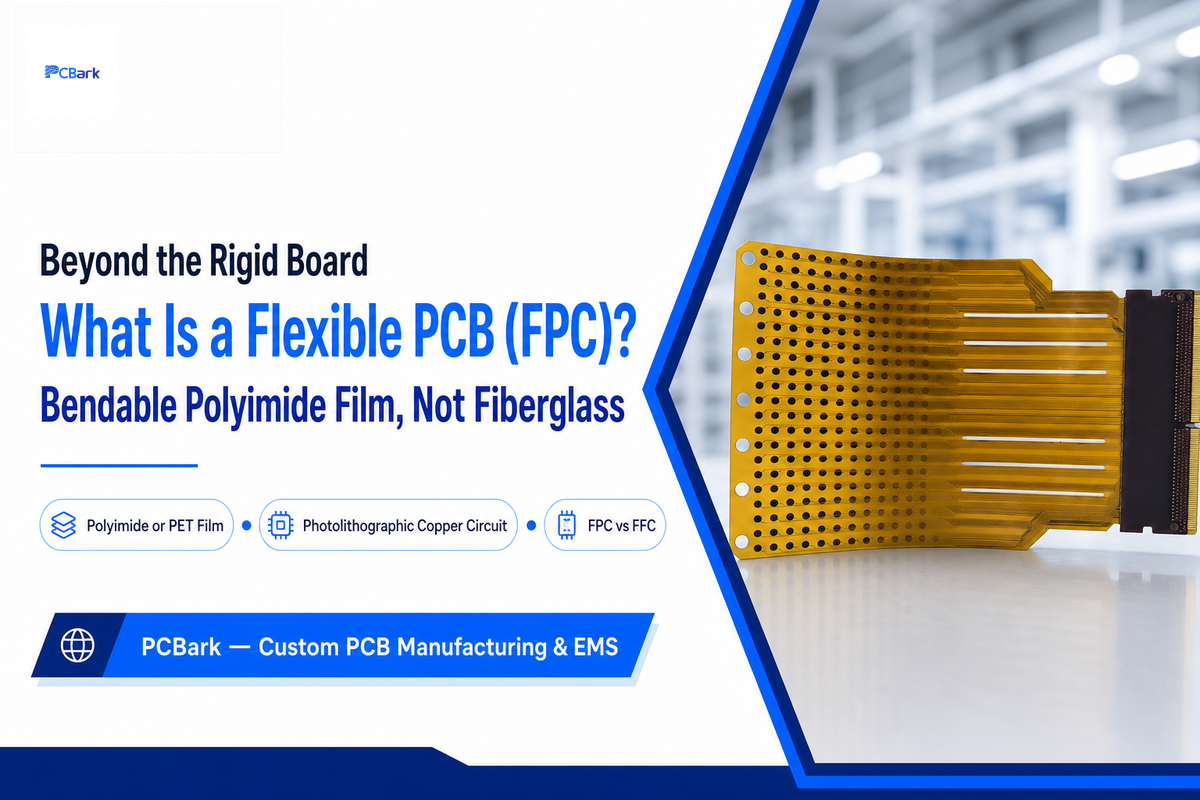
A flexible printed circuit, or FPC, is a circuit built on a bendable polyimide or PET film instead of a rigid FR-4 core. Its copper conductors sit on that flexible film, letting the whole circuit fold, flex, or wrap into a three-dimensional shape inside an enclosure — which is why designers reach for flex whenever a product needs to bend, fold, or fit a tight, contoured space.
Because the circuit can be twisted and folded to fit around internal components, this flexibility helps remove multiple connectors and wires within wearable computers, foldable cell phones, small medical equipment, and various other electronic devices; this in turn reduces the weight and space requirement of the device by replacing those components with one continuous circuit on a single PCB. Since flexible printed circuit boards and other associated technologies have developed a lot over time, today it’s possible to use flex-compatible design paths across several categories of consumer electronics. This guide gives more insight into the ways and circumstances where you can use flexible circuit technology.
You’ll see “FPC” and “flexible pcb” used interchangeably in RFQs and sourcing discussions; your suppliers may use “flex circuit”, “flexible circuit”, “flexible circuit board”, “flex printed circuit”, or “flex printed circuit board”, and they all refer to the same thing. One term worth distinguishing: an FFC (Flat Flexible Cable) is just a simple flat ribbon with parallel conductors and no patterned dielectric. An FPC is what people really mean in a discussion of dynamic PCBs because it has a photolithographically patterned copper layer (or layers), or circuit as the industry calls it, with etching in the dielectric film, or substrate. They’re both flat and flexible, and they look very similar to the untrained eye, but they’re built differently and performance requirements are worlds apart. Confusing the two early in sourcing is a common and expensive mistake: a fabricator quoted to build a simple FFC ribbon cannot silently substitute the photolithographic circuit process an actual FPC design requires. PCBark manufactures both FPC and rigid-flex builds in-house under ISO 9001 and IATF 16949 certification, so this distinction gets caught at the RFQ stage rather than after tooling has already started. Formal qualification and performance criteria for these construction types are set out in IPC-6013E, the governing standard referenced throughout this guide.
Materials That Make a PCB Flexible
There are only two primary material considerations for ensuring your flex circuit design survives its useful life: the choice of base substrate, and the type of copper foil used. Polyimide is generally preferred in applications with challenging thermal and chemical demands due to its ability to withstand short term exposure up to about 260°C, with continuous-use ratings typically in the 150-180°C range. PET is a lower cost substrate option and appropriate for lower temperature and less demanding designs. Copper foil choice is just as important for reliable flex performance, and it’s where most designers (and purchasing departments) fail to invest adequate effort.
The Copper Ductility Divide
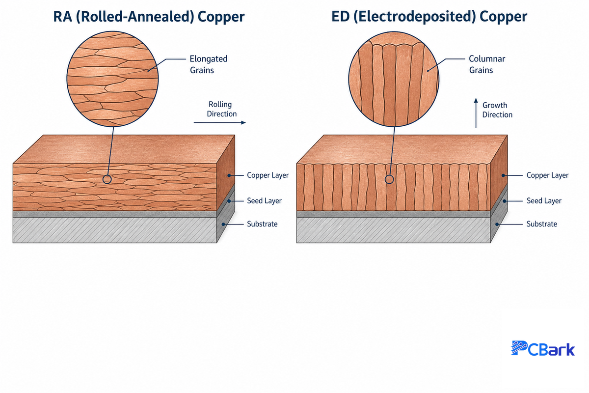
Two distinct types of copper foil are used for flex circuits and the choice is critically important, not merely a cosmetic or cost differentiator. RA (rolled-annealed) copper has an elongated grain structure due to its mechanical rolling and flex industry literature is rife with mention of the unique grain structure and its enhanced resistance to the cyclic mechanical stresses associated with repeated flexing in a moving or cycling system. This ductile grain structure is generally seen as the primary reason for RA’s preferential selection for applications requiring dynamic flex. ED (electrodeposited) copper is grown on the substrate via an electrochemical process, creating a more columnar grain structure. It’s generally considered to be less resistant to repeated flex cycles by industry sources and the general consensus is to use RA copper whenever the device is intended to flex repetitively in service and ED copper only in designs that are formed during assembly and are thereafter intended to remain static, though research into RA vs. ED grain structures and mechanical response in flex can be very general and not specific to any given application or design requirement. It’s extremely common to see designers select ED copper for an application that’s intended to dynamically flex at service – one of the most preventable material selection errors in flex sourcing. An experimental characterization study of rolled-annealed copper independently confirms the ductility mechanism behind this preference.
| Material | Best For | Key Property |
|---|---|---|
| Polyimide film | Dynamic flex, high-temperature environments | Stable to ~260°C short-term, high chemical resistance |
| PET film | Static or one-time-bend, cost-sensitive builds | Lower cost, moderate temperature tolerance |
| RA copper | Dynamic (repeated) flex zones | Elongated ductile grain structure |
| ED copper | Static bend, rigid sections | More brittle columnar grain structure |
What Materials Are Used in Flexible PCBs?
A complete flex stackup needs more than substrate and copper: a protective polyimide coverlay (or hard coat) seals the circuit, adhesive films bond the layers together, and FR4 or stainless steel stiffeners bonded to the flexible base reinforce connector zones and component-placement areas. Multi-layer builds alternate copper foil with dielectric film, adding polyimide stiffeners at stress-relief points along the polyimide flex circuit.
Some high-density constructions also incorporate techniques borrowed from HDI (high-density interconnect) construction, including microvias and finer trace geometries, to maximize routing in a given flex footprint. Ultimately, the performance and reliability of any flex solution depend on how well all of these material layers have been integrated and selected to meet the specific requirements of the application.
Types of Flexible PCB Construction
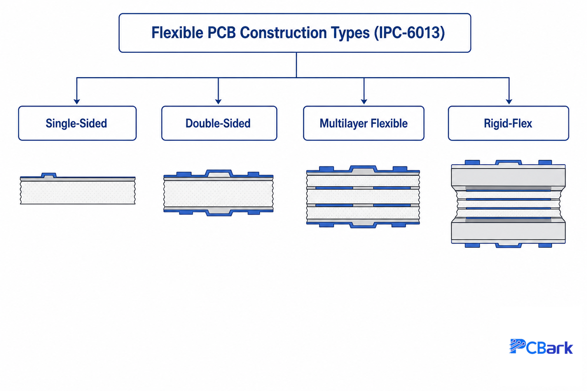
IPC-6013, the performance specification for flexible and rigid-flex PCB structures, classifies flex boards into several types, and understanding which type of flex your application requires will impact your cost and your manufacturability.
| Construction | Description | Typical Use |
|---|---|---|
| Single-sided | Copper on one side of the substrate only | Simple, low-density interconnects |
| Double-sided (double sided flex) | Conductive traces on both sides, plated through-holes connect layers | Moderate routing density |
| Multilayer flexible / complex multilayer | Alternating copper/dielectric layers throughout | High-density, high-speed designs |
| Rigid-flex | Rigid FR-4 sections bonded to flexible sections in one assembly | 3D packaging, connector elimination |
If your design needs to be anchored by some rigid zones that will be embedded directly into the flex assembly – a requirement in very small, 3D packaging in which the desire is to get rid of connectors altogether – then it’s rigid-flex rather than flex. That brings its own issues around bend-envelope and lamination that we discuss in our rigid flex PCB manufacturer guide. Rigid-flex PCB manufacturing isn’t the same thing as either pure flex or pure rigid production because it uses aspects of both, and design rules can differ for flex versus rigid-flex zones on the same PCB. Ask the fabricator whether it has experience producing both flex and rigid-flex PCBAs. In general, use pure flex for board-level mobility or high-density routed paths and rigid-flex where there’s a need to eliminate connectors between moving and stationary segments of the PCB.
How Flexible PCBs Are Manufactured
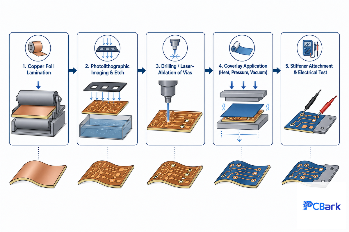
Flexible PCB manufacturing broadly follows the rigid-board process: copper foil is laminated onto polyimide or PET film, then photolithographically imaged and etched to define the circuit, with vias added by drilling or laser ablation. A polyimide coverlay is then applied over the finished circuit under heat, pressure, and vacuum, and stiffeners are bonded wherever a zone needs added rigidity before final electrical test.
In this flexible pcb manufacturing process, control of temperature, pressure, and lamination dwell time — often 150°C to 200°C for tens of minutes under vacuum — matters a great deal; without careful control, lamination can produce the most frequent failure mode in flex: trapped voids and delamination. Finally, the PCBAs are electrically tested and shipped.
There are two very common failure mechanisms in this type of PCB design that can be traced back to these steps: improper imaging alignment (resulting in shorts or opens in the traces), and lamination parameter drift (temperature, pressure or dwell time out of specification, leading to delamination or void trapping). These are process-driven, not design-driven issues; one reason why fabricator evaluation is such an important part of PCB development. These manufacturing processes — PCB fabrication and PCB manufacturing and assembly — are frequently referenced as components of a finished PCBA (printed circuit board assembly), but they are separate steps in electronics manufacturing and electronic manufacturing more broadly, and each is individually qualified. Make sure to inquire of any fabricator whether each step in the process occurs in-house, or if it’s being outsourced — every handoff presents an opportunity for errors in lamination or alignment. Our flex PCB assembly guide covers what happens after fabrication, once the bare board moves into SMT placement and reflow.
Designing for Flex, DFM Rules Engineers Should Know
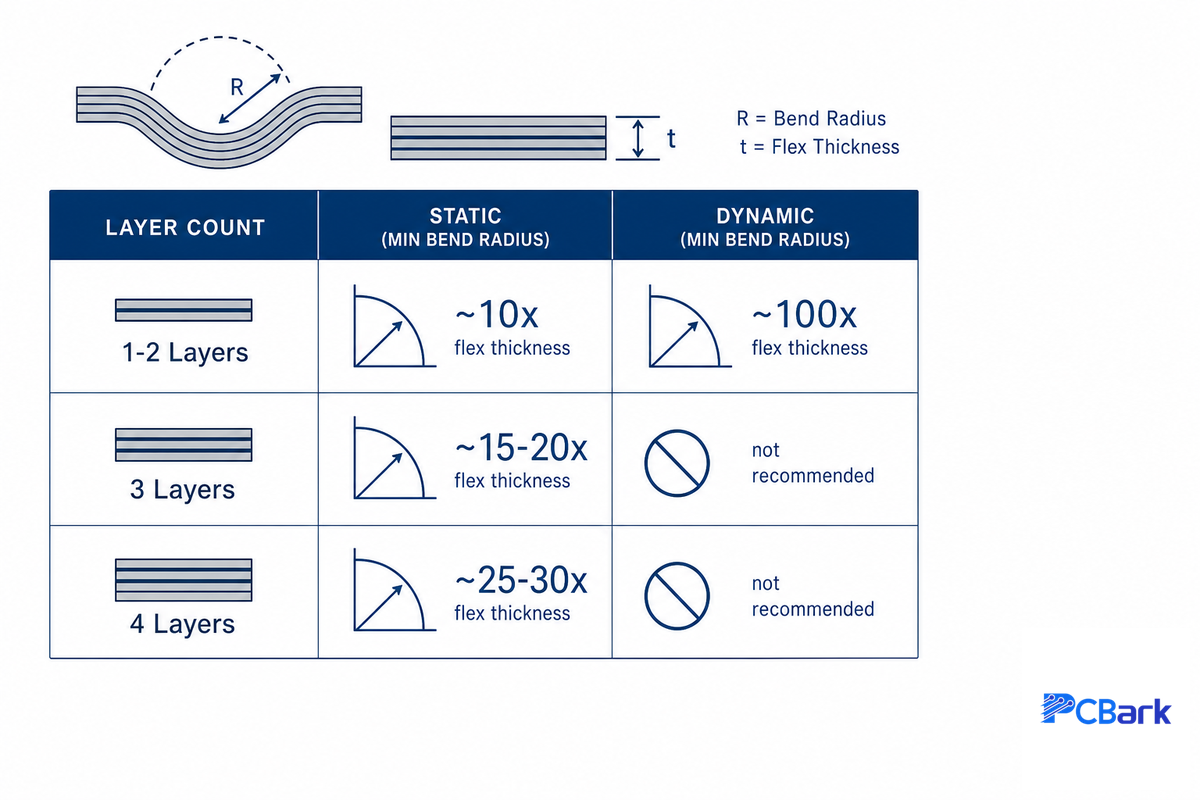
By far the most important design parameter for any flex layout is the bend radius, and ironically, it’s the rule that’s most frequently over-simplified. Flex PCB design guidance commonly breaks application categories into two, with very different rules of thumb for minimum bend radius, and failure to distinguish them leads to most of the flex failures that appear in the field. The numbers below are ubiquitous throughout flex fabricator design guides, not figures independently verified against a specific standard’s primary text — treat them as planning figures, and let your fabricator’s Design Rule Check (DRC) of your specific stackup and materials be the final word.
| Layer Count | Static Bend (one-time) | Dynamic Bend (repeated) |
|---|---|---|
| 1–2 layers | ~10× flex thickness | ~100× flex thickness |
| 3 layers | ~15–20× flex thickness | Generally not recommended for high-cycle dynamic use |
| 4 layers | ~25–30× flex thickness | Generally not recommended for high-cycle dynamic use |
Simply put, if a thin 0.1mm 1-2 layer flex zone needs only a 1mm radius if it will be bent once at assembly, it requires 10x that – a 10mm radius if the device will be bent thousands of times during its service life. This gap is often why designs like a smartphone’s hinge don’t appear to comply with the “6-10x thickness” rule quoted in many buying guides – that rule was written for static, one-time-bend applications, and it simply doesn’t apply to a dynamic hinge design.
What Is the Minimum Bend Radius for a Flexible PCB?
The minimum bend radius depends on whether the flex zone bends once during assembly (static) or repeatedly over the product’s lifetime (dynamic), plus the layer count — dynamic zones need roughly 10 times more radius than static ones for a given layer count. Confirm the exact multiplier with your fabricator, since real differences exist between materials and constructions.
In addition to the raw radius, three details matter at the actual bend point itself: keep component and connector pads completely out of the bend zone using filleted or teardropped pads, use rounded rather than sharp corners to eliminate mechanical stress concentrators, and avoid lining up another layer’s transition with a flex edge transition, since that causes abrupt thickness changes and stress concentrations. Field reports on PCB design forums point to a common habit in dynamic bend applications: minimizing layer count and overall thickness in the flex section, and often specifying 0.5oz rather than 1oz copper, all for the express purpose of reducing the required minimum bend radius.
One last bit of nuance worth keeping in mind before you settle on a stack-up: the more individual unbonded substrate layers in a design, the more flexible it tends to be. But industry design consensus is firm on one point: more flexible doesn’t always mean more reliable, since additional unbonded layers also introduce new potential failure mechanisms if spacing isn’t tightly controlled between the bonded segments. If you’d rather have an engineer confirm the right bend-radius multiplier for your specific stack-up than work from planning figures alone, PCBark’s flexible PCB manufacturing capabilities page is the place to start that conversation.
Where Flexible PCBs Are Used
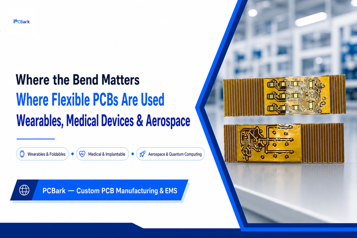
Flex circuits are used wherever a product needs to save space, eliminate wiring, or survive movement that would crack a rigid board and its connectors — spanning wearables, foldable phones, medical devices, automotive electronics, and industrial control systems, plus more specialized cases like implantable sensors and aerospace hardware than most buyer guides mention.
Academic research papers detailing specific flex failure mechanisms include bioimpedance sensors implanted in human beings, so the concern around flex reliability in the medical field is very real. U.S. patents for substrate designs based on flexible pcb exist for high voltage interconnects used in electric vehicles; for expandability of catheter devices used in interventional medicine; and even for interconnects used in a cryogenic attenuator inside quantum computing systems, one of the more advanced technologies where a flexible substrate helps manage extreme low temperatures. A granted patent, of course, means there’s a working design – it doesn’t necessarily translate to production, but it’s still telling about the range of flex PCB applications outside consumer devices.
Ultra-thin flexible polyimide layers make these application scenarios possible, and multilayer and rigid-flex are the primary choices for rugged environments like aerospace and industrial control. As a general guideline, you can sort into: cost-effective, volume consumer applications with simple, single or double-sided flex; and higher cost medical, aerospace and industrial control, where the extra rigidity of multilayer or rigid-flex adds field reliability that justify the expense. Because automotive and industrial programs typically require IATF 16949-certified production controls in addition to IPC qualification, PCBark manufactures flex and rigid-flex boards in-house under that certification, so an OEM in these end markets can qualify a single fabricator instead of splitting flex fabrication and assembly across separate vendors.
What Drives Flexible PCB Manufacturing Cost
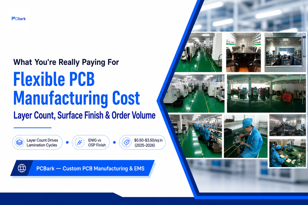
Flex boards cost more per piece than an equivalent rigid design — the reasons are structural, not arbitrary pricing. Layer count and surface-finish choice are the two biggest levers, both of which compound with order volume to determine your final per-unit price.
Flex boards are usually more expensive per piece than a comparable rigid version, but that expense isn’t arbitrary, it’s built-in to the product. The largest driver is layer count; more layers mean more lamination cycles, and rigid-flex constructions carry particularly heavy cost premiums since both the rigid-flex polyimide material and sequential lamination add cost over a one-shot rigid design. Choice of surface finish can add costs as well, with ENIG generally more expensive than OSP but a more durable finish for fine pitch components and longer shelf life, while OSP is good for short turnaround prototype production where cost is more important than long-term storage stability. Cost is further driven up on prototype runs and low volume production by spreading tooling and setup costs across far fewer boards; current (2025-2026) price benchmarks often list single layer flex in the $0.50 to $1.20 range and two-layer flex in the $1.80 to $3.50 range, and single prototype builds can easily run many times their eventually-manufactured cost. These are intended as background numbers for guidance only, consult with your specific fabricator for a quotation for your build.
Similar to above, your flex pcb cost is also dependent on order size; a rapid prototype of a flex PCB will cost more on a per-unit basis than a full-scale production order with the same flex PCB design, as tool/setup costs are amortized over many more boards. Turn times generally vary from around 3 days for a basic single layer prototype to more than 15 days for complex rigid-flex PCBs or multilayer builds. For an itemized quote against your own stack-up rather than these background figures, request a real number directly from your fabricator.
Are Flexible PCBs More Expensive Than Rigid PCBs?
Yes, per unit when compared head-to-head, on a like-for-like basis. Additional lamination cycles, unique flex materials, and generally poorer panel utilization add cost when comparing a single-layer flexible construction against a single-layer rigid one. The differential is much less dramatic at production volumes when tooling and setup costs are spread over many units and can be well worth it to eliminate connectors, cables and associated assembly labor/failure points even if the cost premium is present.
Quality Standards and Testing for Flexible PCBs
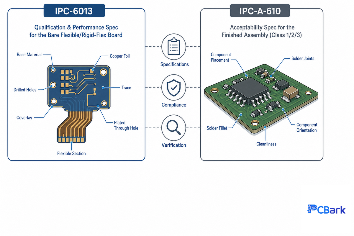
There are two standards that govern the quality of your flex pcb – they actually relate to two very different points in the product life cycle. IPC-6013 describes the quality of the bare flexible or rigid-flex board before assembly. IPC-A-610 is the acceptability specification for the finished assembly and dictates acceptable assembly work and components on the board, up to and including soldering and testing. Both standards include the three quality levels, or Classes (1 through 3), as mentioned in our other article but a manufacturer certified to A-610 isn’t necessarily qualified according to 6013 and vice versa.
In addition to IPC certification, you’ll want to look for UL recognition on any flex pcb destined for a UL-listed end product, since UL’s specific tests for PCBs–thermal and environmental conditioning, flammability, and interconnect stress–all feed directly into long-term reliability and durability in a way that a generic IPC workmanship standard doesn’t. A good manufacturer will also run production test coupons of the same type and on the same panel as your boards, providing proof, both destructively and nondestructively, that a given production lot met standards for thermal cycling (roughly -40°C to 125°C) and cross-sections demonstrating plate thickness within the 20-35µm range on plated features, rather than just relying on a once-off qualification — the same lot-and-panel test-coupon discipline NASA’s own flex PCB acceptance standard requires for vendor qualification. For those in the aerospace/defense supply chain, check also for IPC-1791 trusted supplier status, as these programs add supply chain security measures to the qualification standard that aren’t included in general commercial certification.
💡 Pro Tip
Ask your manufacturer for both the bare board qualification (IPC-6013 class) and the assembly acceptance class (IPC-A-610 class) in writing. If the quoted figure only references one or the other, they haven’t addressed the question properly.
Common Flex PCB Sourcing Mistakes to Avoid
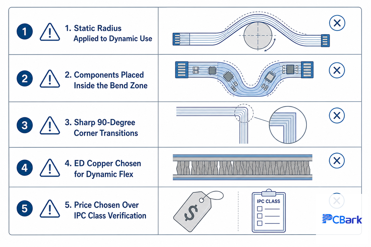
Almost all flex pcb failures fall into a few well-understood categories, all of which can be avoided during design or manufacturer vetting — but are much harder to fix during the fabrication stage. Working with a fabricator that reviews your flex PCB design before quoting catches most of these before they ever reach the shop floor.
- Applying a static bend radius to a dynamic (repeated flex) application, or vice-versa — be sure which category you’re in before selecting a stackup configuration.
- Positioning components or connector pads either in the middle of a bend area, or right next to one where an unprotected, ENIG-plated pad can crack under repeated flex.
- Using 90-degree corners or letting stiffener and coverlay edges terminate together at one spot, which creates concentrated stress in the bend area.
- Choosing ED copper because it’s standard on the quote for a dynamic application rather than selecting the RA copper specified in the bending zones that will repeat the flexing cycle.
- Selecting a flex pcb fabricator based solely on quoted price without verifying their IPC-6013 class, IPC-A-610 class, and any additional relevant qualifications and controls match the requirements of your end product.
How to Evaluate a Flexible PCB Manufacturer
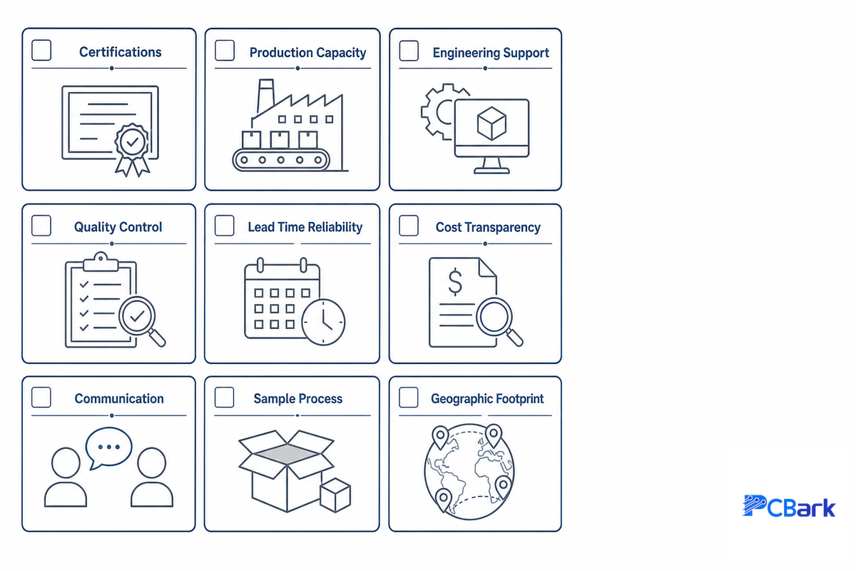
There’s no single best flexible PCB manufacturer for every project — the right partner is the one whose fabrication capability, certifications, and process controls line up with your specific stack-up and volume requirements. Top-tier manufacturers pair fabrication capability with the engineering support needed to catch potential failures before they reach the manufacturing floor.
Choosing a flex pcb manufacturer is far more about selecting for a particular set of capabilities and process controls that match your product requirements than it’s about chasing the cheapest quote — the best flex pcb manufacturers earn repeat business on capability match, not price alone. Leading suppliers use an audit process which measures a candidate against a standardized set of criteria to qualify as a supplier – applying a similar, focused pass-fail structure is an excellent approach for vetting flex-specific suppliers.
The 9-Point Manufacturer Vetting Scorecard
| Vetting Category | What to Ask For | Why It Matters |
|---|---|---|
| Certifications | IPC-6013 class, IPC-A-610 class, ISO 9001, IATF 16949 (automotive), ISO 13485 (medical), UL recognition | Matches capability claims to your end market’s actual requirements |
| Production capacity | Evidence of both low-volume and production-run experience | Confirms they can scale with you from prototype to production |
| Engineering support | DFM review process, stack-up consultation, test-coupon practice | Catches design issues before they become yield problems |
| Quality control | AOI, electrical test, and inspection methods used per lot | Determines defect escape rate to your production line |
| Lead time reliability | Track record on quoted vs. actual delivery, typically 3-15 days by complexity | Protects your own production schedule commitments |
| Cost transparency | Itemized quote by material, layer, and finish rather than one lump figure | Lets you value-engineer for best value without guessing where the cost sits |
| Communication & responsiveness | Typical RFQ turnaround and named engineering point of contact | Predicts how design issues get resolved mid-production, not just before it |
| Sample / first-article process | Whether first-article samples are offered before a full production commitment | Catches stack-up or process issues on a small batch instead of a full run |
| Geographic & logistics footprint | Factory location(s), shipping lead time, and tariff/export exposure | Affects total landed cost and schedule risk beyond the unit price |
For aerospace/defense programs, you can add a line item for that to your scorecard: verify the vendor has IPC-1791 trusted supplier status, as regulated government procurement processes increasingly incorporate supply chain security protocols in addition to general manufacturing qualifications.
Once your shortlist has passed this quality filter, the question becomes how to present a specific design to the engineering team at a potential manufacturer. If you’re ready for that conversation, check out PCBark’s flexible PCB manufacturing capabilities for a capability-matched quote. And if your flex boards require SMT assembly after fabrication, that’s a separate qualified process step, not an automatic extension of the fabrication contract.
Request a Flex PCB Manufacturing Quote →
Ask Our Engineering Team a Question
Industry Outlook, What’s Changing in Flex PCB Manufacturing
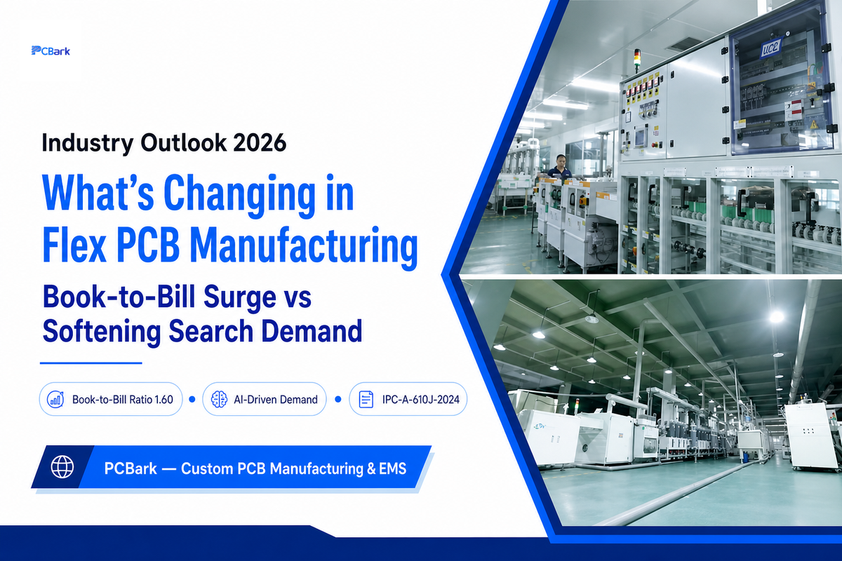
(Updated July 2026) The North American PCB industry is running hotter than at any point in recent memory: the Global Electronics Association’s May 2026 statistics put the book-to-bill ratio at 1.60, with bookings up a striking 102.8% year-over-year for the month and 28.6% year-to-date (the Association also flagged an updated survey methodology starting with this report, so month-over-month comparisons to earlier 2025 figures should be read with some caution).
“The AI build-out continues to fuel strong bookings that have driven the PCB book-to-bill to historic levels. Shipments are keeping pace, up 11.9% over last year and 10.1% from April, while year-to-date orders run 28.6% ahead.”
— Dr. Shawn DuBravac, Chief Economist, Global Electronics Association
That industry-wide surge sits oddly alongside a separate signal: DataForSEO keyword search volume for “flex pcb manufacturer” and related terms is down roughly 46% over a comparable period (a keyword-planner-style search-volume statistic, not a Google Trends relative-interest reading). Search demand for new-supplier terms and real industry order volume are most plausibly just measuring different things: OEMs riding the AI-driven demand wave appear to be expanding orders with fabricators they already qualified, not searching for new ones. For a buyer evaluating suppliers right now, that’s still useful context — manufacturers actively investing in engineering support and transparent capability information are competing for a shrinking pool of active searchers even as the industry itself is unusually busy.
As with any of the most advanced PCB technologies, flex pcb technology continues to borrow features from closely related segments of PCB tech, including HDI microvia technology, fine traces, and hybrid rigid-flex designs. IPC will continue its iterative updating of design and qualification documents. PCB designers will need to be sure that they’re using the current version of the IPC-6013 design specification and IPC-A-610 acceptability standard (current edition IPC-A-610J-2024) instead of a stale cached document because IPC will revise acceptable criteria. For now, this means that your RFQ for flex boards should specifically ask potential suppliers what versions of IPC-6013 and IPC-A-610 they meet as opposed to asking for “IPC-qualified boards.”
Frequently Asked Questions
Q: How many layers does a flex PCB have?
View Answer
Flex PCBs range from a single conductive layer up to six or more layers in high-density multilayer builds. Single-sided flex suits simple, low-density interconnects; double-sided adds plated through-holes for roughly double the routing density; and multilayer stacks alternating copper and dielectric film for designs that genuinely need the extra density.
Every additional layer adds a lamination cycle, cost, and a stiffer overall cross-section that works against the flexibility the design needed in the first place. Rigid-flex designs add a further wrinkle by combining multiple flex layers with bonded rigid FR-4 sections in the same assembly.
Q: How many times can a flexible PCB bend before failing?
View Answer
There’s no single cycle-life number that applies across all designs — it depends on copper type, bend radius relative to thickness, layer count, and whether the design follows dynamic-bend DFM rules. A properly specified dynamic design using RA copper, a generous bend radius (roughly 100 times the flex thickness for thin 1–2 layer builds), and components kept clear of the bend zone can sustain a very high number of flex cycles in service.
The same layer stack built to static-bend tolerances and then flexed repeatedly will work-harden the copper and crack in a small fraction of that cycle count. Request cycle-test data from your manufacturer for your specific stack-up rather than relying on a generic industry figure.
Q: When should you use a flexible PCB instead of a rigid one?
View Answer
Reach for flex when the product needs to save space or weight by eliminating connectors and wiring harnesses, when the circuit needs to move or bend as part of normal operation, or when the assembly has to wrap around a non-planar enclosure shape. Stick with rigid PCB when the design is flat, static, and cost-sensitive, since flex carries a real cost premium that isn’t always justified.
Q: Why not make all circuit boards flexible?
View Answer
Cost and design complexity are the two practical reasons, and both are structural rather than arbitrary supplier pricing. Flex fabrication needs specialized polyimide materials, additional lamination steps, and tighter process control than a single-shot rigid FR-4 board, adding to unit cost.
That premium is one industry cost analyses commonly describe as several times a comparable rigid design, and substantially more for rigid-flex builds specifically. Design complexity rises too: engineers have to account for bend radius, dynamic vs. static use, copper ductility, and stress concentrators that simply don’t exist in a flat rigid board. For any application that doesn’t actually need to bend, move, or save enclosure space, a rigid board delivers the same electrical function at lower cost and lower design risk — which is exactly why flex is targeted at applications where its specific benefits are actually needed, not used as a universal default.
Q: What are the disadvantages of a flex PCB?
View Answer
Higher unit cost relative to an equivalent rigid design is the most consistent disadvantage, driven by specialized materials and additional lamination steps. Design and rework complexity is another: a flex layout carries bend-radius, copper-ductility, and stress-concentrator constraints that a rigid board simply doesn’t, raising the skill bar for both designer and fabricator.
Rework on an installed flex circuit is also harder than on a socketed rigid board, and flex circuits are more sensitive to handling during assembly — bending a flex zone near an unsupported ENIG-finished pad or forcing a connector insertion incorrectly can crack a board that would otherwise have met its full service life, so assembly-line training matters more than it does for rigid boards.
Q: What’s the difference between FPC and FFC?
View Answer
An FPC has a photolithographically etched copper circuit pattern on a flexible polyimide or PET film, while an FFC (Flat Flexible Cable) is a simpler flat ribbon with parallel conductor strips and no patterned dielectric. They look similar to the untrained eye, but an FPC is what people mean in a discussion of dynamic, moving-circuit designs.
References & Sources
- IPC-6013E, Qualification and Performance Specification for Flexible and Rigid-Flex Printed Boards — IPC (Association Connecting Electronics Industries)
- GSFC-STD-8001, Standard Quality Assurance Requirements for Printed Circuit Boards — NASA Goddard Space Flight Center
- IPC A-610J-2024: Acceptability of Electronic Assemblies — American National Standards Institute (ANSI)
- Experimental characterization of rolled annealed copper for flexible printed circuits — Girard et al., HAL Open Science
- Flexible PCB Failures From Dynamic Activity and Their Mitigation — Critcher et al., PMC (National Library of Medicine)
- North American PCB Market Gains Momentum with 1.60 Book-to-Bill Ratio in May — Global Electronics Association
- US20140212695A1, Flexible Printed Circuit as High-Voltage Interconnect in a Battery Pack — USPTO / Google Patents
- US20220083893A1, Quantum Computing System Having Flex Circuit Boards — USPTO / Google Patents
Why We Write This
PCBark fabricates flexible, rigid-flex, and rigid PCBs under ISO 9001, ISO 14001, IATF 16949, and IPC-A-610 Class 2 & 3 qualification, and this guide reflects the same bare-board-versus-assembly standards distinction our own quoting process asks every flex customer to work through.
We wrote this guide because most buyer-facing content in this category quotes a single bend-radius number without separating static from dynamic use, a distinction that materially changes whether a design survives its service life. Reviewed by the PCBark technical team.
Related Articles
- Rogers PCB: The Complete RF Substrate Guide — material selection for high-frequency boards
- Gold Finger PCB: Type Taxonomy and Insertion-Cycle Guide — connector-edge plating for card-edge designs
- Ceramic PCB: Materials, DFM, and Reliability Guide — high-thermal-conductivity substrate alternative
- Aluminum PCB: Fit Test and Sourcing Guide — metal-core PCBs for thermal management






![High Frequency PCB Guide: RF & Microwave Design [2026]](https://pcbark.com/wp-content/uploads/2026/07/rf-microwave-pcb-guide-featured-1-150x150.png)