Get in touch with PCBark Company


Quick Specs
| Base material | Aluminum (most common), copper (higher performance), or aluminum alloy |
| Layer count | Typically single- or double-sided; deep multilayer builds are mechanically difficult |
| Dielectric thickness | Commonly reported 50-200 μm (varies by material spec sheet, not one universal figure) |
| Copper weight | 1-10 oz (thicker than typical FR4 builds) |
| Also known as | Metal core PCB (MCPCB), aluminum clad, insulated metal substrate (IMS) |
An aluminum PCB (actually metal core printed circuit board, or MCPCB) replaces the glass base in a normal board with a metal core that conducts heat away from your board, preventing heat build-up beneath hot components. This research published via the U.S. National Library of Medicine (PMC) on flip-chip LED assemblies uses exactly this construction to model junction-temperature behavior, showing how central the metal base is to real thermal engineering, not just marketing language.
In Short
- An aluminum PCB substitutes the metal basis for a fiberglass base, allowing it to more rapidly transmit the heat outside of the circuit.
- Its copper circuit layer stays exactly the same as on any other board, only the base material and the dielectric between them are different.
- It’s not automatically cheaper than FR4; it wins when thermal performance, not price, is the driving factor in the design.
What Is an Aluminum PCB (Metal Core PCB / MCPCB)?
For: Engineers evaluating a thermal-management approach
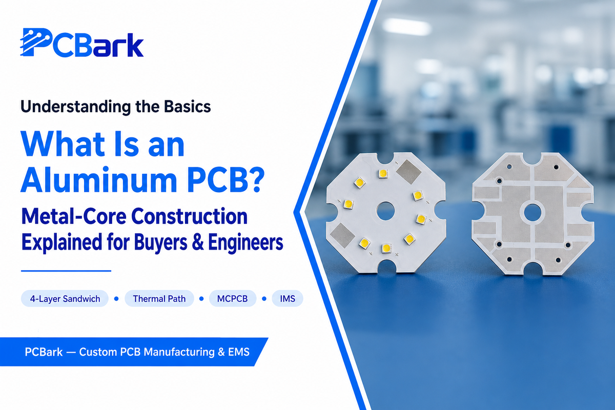
An aluminum PCB is the same kind of board engineers already know, built with a metal substrate instead of fiberglass. The top side has the standard copper circuit, solder mask, and silkscreen layers, same as any PCB, but underneath is different: an electrically insulative, thermally conductive dielectric sits between the copper layer and the metal base, keeping electricity in the circuit while heat dissipates down through the metal.
The confusion doesn’t end there, though, as a number of different names all mean effectively the same thing: aluminum PCB boards, aluminum substrate, aluminum clad board, aluminum base board, metal core PCB (MCPCB), metal clad printed circuit board, insulated metal substrate (IMS or IMPCB), and thermally conductive PCB. Each of these terms describes a PCB where the copper circuit has a backing made of metal (usually aluminum, sometimes copper) that carries heat away. That’s what’s called for in an MCPCB, and industry folks generally refer to the boards as aluminum PCBs and MCPCBs with equal frequency. Whatever the name, an aluminum PCB manufacturer is building an aluminum circuit board that uses aluminum for heat transfer. This construction shows up well outside typical commercial electronics, too — a Fermilab (U.S. Department of Energy) instrumentation paper uses an aluminum PCB as part of a cryogenic sensor package, wrapped in multilayer insulation, which is a useful reminder that this basic metal-base construction scales from consumer LEDs all the way up to national-laboratory hardware. Internationally, you’ll also see it written as aluminium circuit board (British spelling) or, more formally, aluminum printed circuit boards; an aluminum core PCB by any of these names describes the same construction. Worth a brief note on the structure of aluminum used across these names: whether a supplier calls its catalog item aluminum boards, aluminum substrate, or circuit boards with aluminum, the underlying construction is the same three-layer build described below. This naming overlap creates a real sourcing risk worth flagging: a buyer who specs “IMS” while a factory quotes a generic “thermal PCB” can end up mismatched, because neither term forces anyone to confirm the actual dielectric thickness or metal-base thickness before the order is placed, and that gap only surfaces after the board fails in the field. PCBark’s engineering team confirms these specs on the quote itself rather than leaving them to a naming assumption, precisely because a 50 μm dielectric and a 200 μm dielectric both get called “IMS” in casual conversation but perform very differently under load.
💡 Key Takeaway
The board itself is the usual copper-circuit layout, but with one substitution in terms of structure: a metal base replaces the usual fiberglass structure, along with a custom thermal dielectric layer. Silkscreen, solder mask, and copper layout all follow the normal rules of the road for a printed circuit board.
Anatomy: The 3-Layer Structure Behind Every MCPCB
For: Engineers speccing a stackup
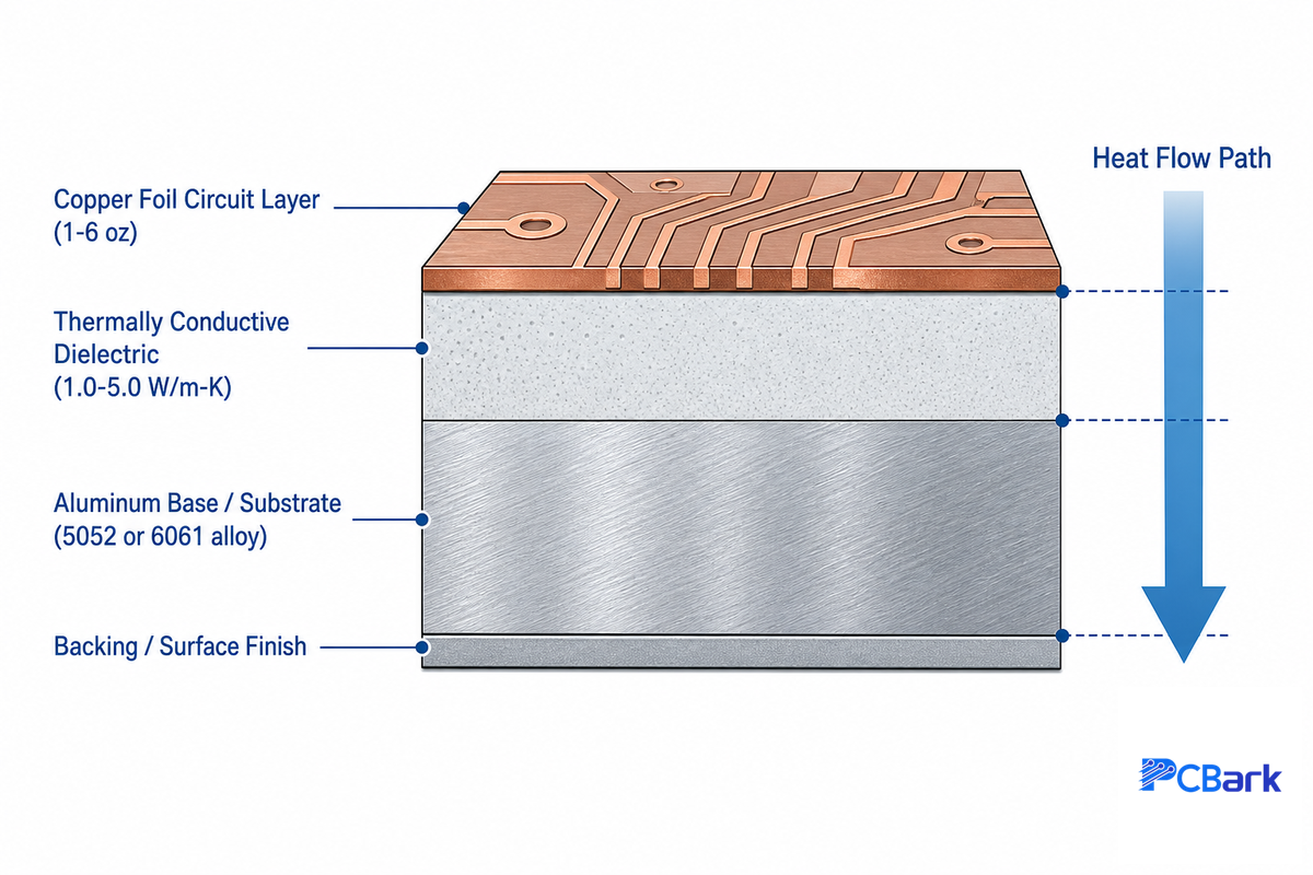
If you take an aluminum PCB apart, there are actually three distinct working layers (and potentially a fourth that’s added) performing separate tasks. If you understand what each layer actually is, as opposed to just knowing the name of it, you can ask the fabrication shop a pointed question when a board feel too warm.
| Layer | Function | Typical Thickness |
|---|---|---|
| Copper circuit layer | Carries current and routes the circuit, same as any PCB | 1-10 oz (thicker than most FR4 designs) |
| Dielectric layer | Electrically insulates copper from the metal base while conducting heat downward | Commonly 50-200 μm (material-spec dependent, not a fixed industry standard) |
| Metal base | Spreads and dissipates heat away from the circuit; provides mechanical rigidity | Varies by application, commonly 0.8-3.2mm |
| Base membrane (optional) | Protects the exposed metal surface from scratching or unwanted etching during fabrication | Thin protective film, two temperature grades (~120°C and ~250°C rated) |
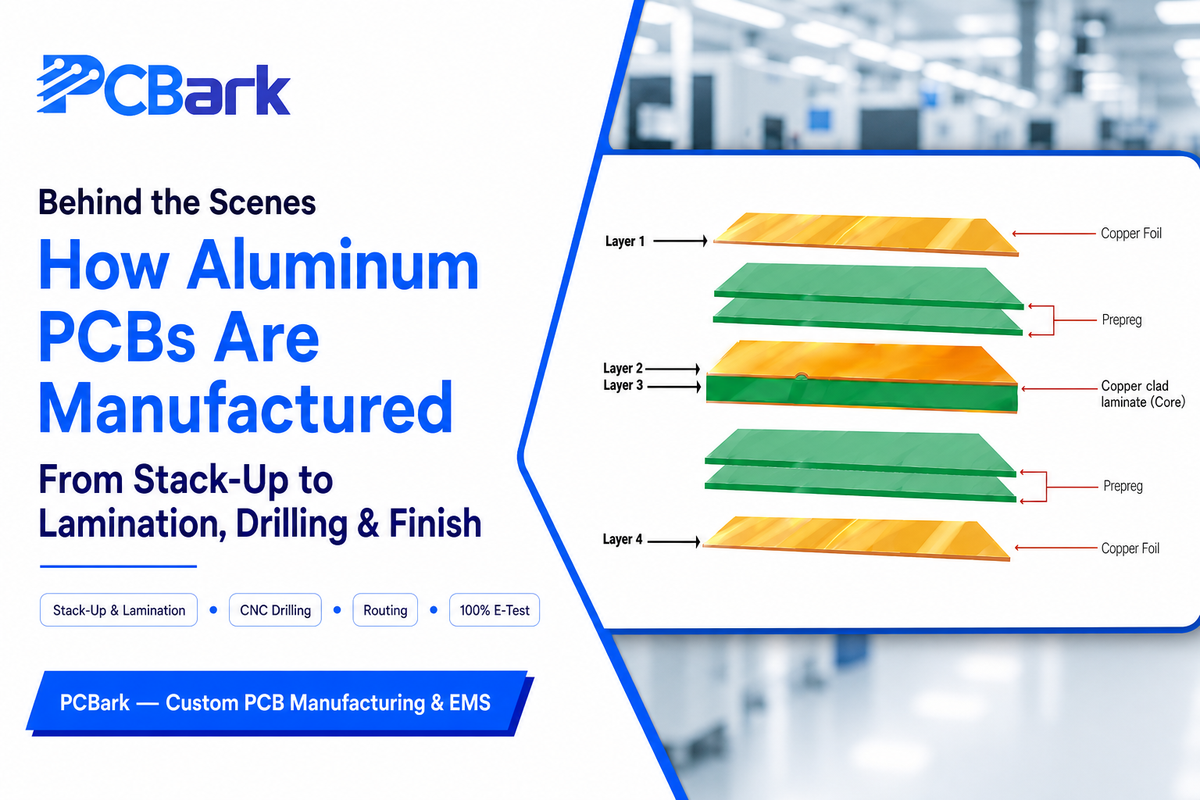
Knowing what aluminum PCB construction is made of begins with its stackup, sometimes just called a PCB stackup in fabricator datasheets: a copper foil layer and conductive layer on top, a dielectric in the middle, and a layer of aluminum at the bottom, protected in some designs by an aluminum base membrane layer. Most designs stay single-sided aluminum rather than attempting a true multilayer aluminum build, because, although commercially available, multilayer aluminum construction is mechanically demanding and reserved for complex power designs with relatively few applications, which is why most boards with aluminum stay single- or double-sided rather than multilayer. A 2 layer aluminum PCB — one copper circuit layer bonded over the aluminum base through a single dielectric — covers the large majority of real designs, from LED strips to power converters, without ever needing the multilayer complexity described above. Readers hunting for full metal core PCB design guidelines — trace-width rules, via placement, thermal-relief patterns — will find that as a dedicated deep-dive elsewhere; this section covers the foundational aluminum PCB stackup knowledge those guidelines build on. Among the mulilayer aluminum (multilayer) options that do exist, most fabricators still recommend the simpler 2-layer route unless routing density genuinely forces the issue.
The dielectric make or breaks your thermal performance – not the metal base. A thicker dielectric more effectively withstands a higher voltage, while conducting heat less effectively; a thinner one does the opposite. This is a trade-off that you can and should make as a design decision, which is why the ‘right’ dielectric thickness depends on material data sheet specs rather than a single universally accepted industry number.
One structural limitation that should be understood early on: because building a true deep multilayer stack on a solid metal core proves mechanically challenging, most aluminum PCBs stay single- or double-sided — one patent describing multilayer PCB core fabrication confirms the core for a multilayer build has to be assembled from a commercially available base material rather than simply stacking more aluminum layers the way a designer might stack additional FR4 layers. If your design requires highly dense, deep multilayer routing with buried vias, a standard FR4 board (or a similarly constructed substrate with heavy copper pours and thermal vias) likely remains the better option, with the aluminum core reserved for the area that actually get hot.
[Named Hook] Aluminum-Core vs Copper-Core Cost-to-Conductivity Snapshot
![[Named Hook] Aluminum-Core vs Copper-Core Cost-to-Conductivity Snapshot — PCBark](https://pcbark.com/wp-content/uploads/2026/07/aluminum-metal-core-pcb-guide-h2_03-1.png)
For: Engineers choosing between metal-base options
When weighing thermally conductive PCB options, aluminum is the dominant choice because it strikes a balance: reliable thermal conduction without excessive weight or cost. Copper provides significantly better heat conduction but is heavier and more expensive, making it suitable only when the thermal load absolutely necessitates it.
| Factor | Aluminum Core | Copper Core |
|---|---|---|
| Relative thermal conductivity | Good (base metal itself) | Higher |
| Weight | Light | Roughly 3x heavier than aluminum by volume |
| Relative cost | Lower | Higher |
| Typical fit | LED lighting, general power electronics, automotive | Highest power-density boards where aluminum’s thermal ceiling is reached |
In cases of extremely high power density, ceramic substrates such as alumina (Al2O3) or aluminum nitride (AlN) surpass any metal-core PCB in thermal performance, although at a substantially increased cost. This is an entirely different material system from metal-core PCBs (being a ceramic insulator instead of a metal base coupled with a dielectric layer), and deserves consideration if your design operates at that level of power density; consult our ceramic PCB capability breakdown for further details.
Aluminum PCB vs. FR4: When Metal-Core Actually Wins
For: Engineers deciding whether to switch materials
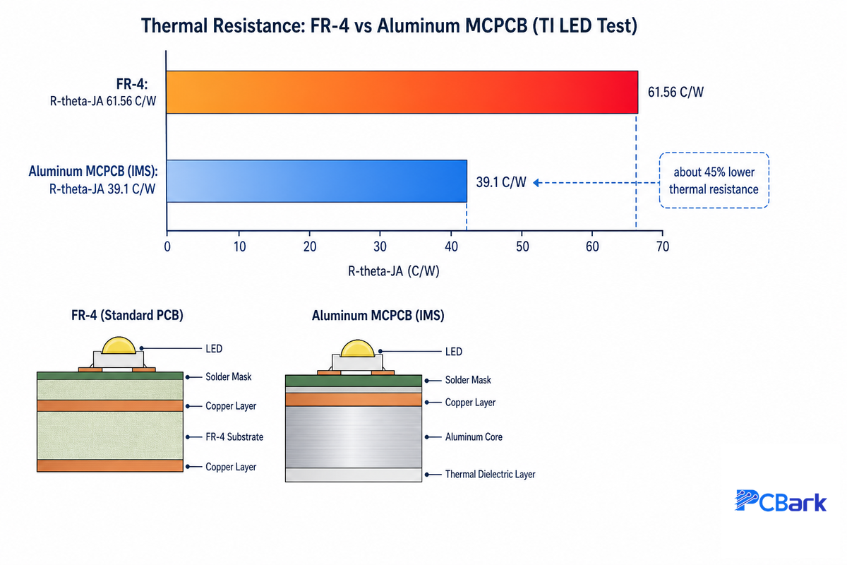
The aluminum PCB vs FR4 decision ultimately comes down to whether your design’s heat problem is bigger than its budget problem. Basic FR4 laminate is on the order of 0.3 W/mK, but Aluminum PCB dielectric is commonly quoted as 1-2+ W/mK; quite a jump for a board with hot components. A Texas Instruments application report comparing FR-4 and insulated-metal-substrate PCBs for a GaN motor-drive inverter measured this gap directly: in a natural-convection test with bottom-cooled GaN FETs, the FR-4 board’s junction-to-ambient thermal resistance came in at 61.56°C/W versus 39.1°C/W for the IMS board on the same top-side FET position, a 45% reduction. Both boards were tested at a 25°C ambient, and the case temperature rise for that FET dropped from 47°C on FR-4 to 32°C on the metal-core board. That’s a real, meaningfully smaller gap than some marketing copy implies, and TI’s own data shows why: the heatsink itself dominates the overall thermal resistance budget in natural convection, so the PCB substrate choice is one lever among several, not the whole story.
That margin is hardly the end of FR4 as soon as the PCB begins to warm up; a power-electronic-substrate document shows a conventional FR4 board is still viable if the device is properly connected to a heatsink, and that heat dissipation may be improved considerably using thermal vias or even the extensive copper pouring often used to spread the heat on such boards before a metal core is called for. TI’s own study makes the same point from the data side: a thicker, better-mounted FR-4 board with a proper phase-change TIM can close a meaningful share of that 45% gap without ever switching substrates.
Decision Framework: FR4 vs. Aluminum PCB
- Low-to-moderate heat, room for a heatsink and thermal vias → Standard FR4 with thermal vias and heavy copper pours is usually sufficient and cheaper.
- Sustained high heat, LED or power-converter component with no room for an external heatsink → Aluminum PCB is the standard choice.
- Extreme power density, automotive or industrial reliability requirement → Consider copper core or a ceramic substrate rather than pushing aluminum past its practical limit.
Worked example, using TI’s measured figures directly rather than a rough estimate: a bottom-cooled GaN FET dissipating enough heat to need a PCB in its primary thermal path sees roughly a 45% higher junction-to-ambient thermal resistance on FR-4 (61.56°C/W) than on an equivalent metal-core board (39.1°C/W), which showed up as a 15°C lower case temperature rise (47°C vs 32°C) in TI’s test, both boards run under identical ambient conditions and power levels. That’s the kind of margin that decides whether a design meets its junction-temperature spec with room to spare or runs right up against it. Get this decision wrong in the other direction and the risk is real: an FR4 board pushed past its practical thermal ceiling degrades component lifespan gradually rather than failing outright, which means the mistake often surfaces as a field-returns problem months after shipment rather than a bench-test failure caught before launch. PCBark flags that failure mode specifically during design review, because it’s a costly and hard-to-diagnose gap when it’s discovered by a customer instead of an engineer.
How Aluminum PCBs Are Manufactured: A Stackup Overview
For: Engineers sourcing from a new fabricator
Aluminum PCBs are manufactured through the same broad fabrication flow as any circuit board: preparing the substrate, laminating the dielectric, bonding the copper layer, imaging the circuit, etching, drilling, and final inspection. A patent on integrated heat spreaders for light-emitting devices lists metal-core PCB alongside standard FR-4 and flex tape as interchangeable substrate choices in that same process. Only a handful of subtle changes matter, and only because the substrate is metal, not fiberglass.
Most fabricators also recommend a short-run aluminum PCB prototype for approval before running at volume, specifically to confirm the stack-up performs as modeled before committing to a full production order.
- Copper Etching – for a rough 3oz of copper, intentional compensation of trace widths must be added or your etched trace will be thinner than expected and be out of specification.
- Solder mask printing The thick copper leads to a large step between the top of the trace and the base board, causing many fabricators to print a two-pass solder mask to obtain a uniform coverage of the resist.
- Drilling The base metal is less compliant than fiberglass, requiring drill parameter adjustment in order to prevent the creation of an aluminum edge burr around the drilled hole.
On the assembly side, there’s a potential issue that many competitors guides fail to mention: that the very thermal-spreading property that makes aluminum PCBs desirable also works against you when you’re trying to do reflow soldering. As one engineer eloquently phrased it on a public forum about aluminum PCB fabrication, “ the metal-core just wicks away heat so quickly during reflow that you’ll start to get tombstones “. Any PCB with a history of tombstones would probably need a custom reflow profile rather than using a standard FR-4 reflow profile.
Where Aluminum PCBs Go to Work: LED, Automotive & Power Electronics
For: Engineers and managers mapping their own use case
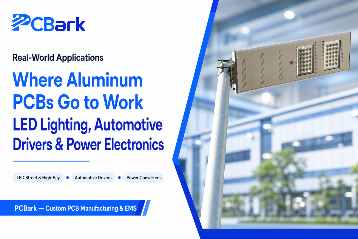
The applications of aluminum PCBs vary wildly, but by far the largest one today is still in LED lighting. LED’s concentrated heat can reduce lifespan and burn them out prematurely. This is exactly the pattern described in EDN Magazine’s engineering coverage of LED thermal management: a thermal-clad MCPCB stack-up placed directly under the LED die to pull heat out before it accumulates. At the finished-fixture level, commercial LED lighting from Guangqi provides application context for a luminaire enquiry; the actual board material and thermal path still need confirmation for the chosen fixture.
Automotive lighting adds a further wrinkle: the PCB substrate must withstand vibration and temperature changes over several years in the field, not just dump heat once. EE Times’ analysis of long-lived vehicle lighting lines up metal-core PCB against alumina (Al2O3) and aluminum nitride (AlN) substrates as the three realistic options for this exact requirement. Knowing when to step up to an alumina or aluminum nitride substrate instead of assuming that an aluminum one will suffice is the key takeaway, because the failure mode here is delayed rather than immediate: a board that passes bench testing at room temperature can still crack or delaminate after repeated thermal cycling in an engine bay, and that risk shows up as a warranty claim rather than a design-review flag. PCBark’s automotive-grade builds run against AEC-Q and IPC-6012DA reliability testing specifically to catch that gap before a customer does.
✔ Where Aluminum PCB Fits Well
- LED lighting (street, high-bay, automotive)
- Power converters and inverters
- Motor controllers
- General automotive electronics with moderate power density
⚠ Where It Struggles
- Dense multilayer digital designs (routing depth limited)
- Extreme power-density modules (ceramic or copper core fits better)
- Applications needing through-hole components on the metal side without added design work
IPC-6012 and the Class System: What “Class 2 vs Class 3” Means
For: Engineers writing a purchase order
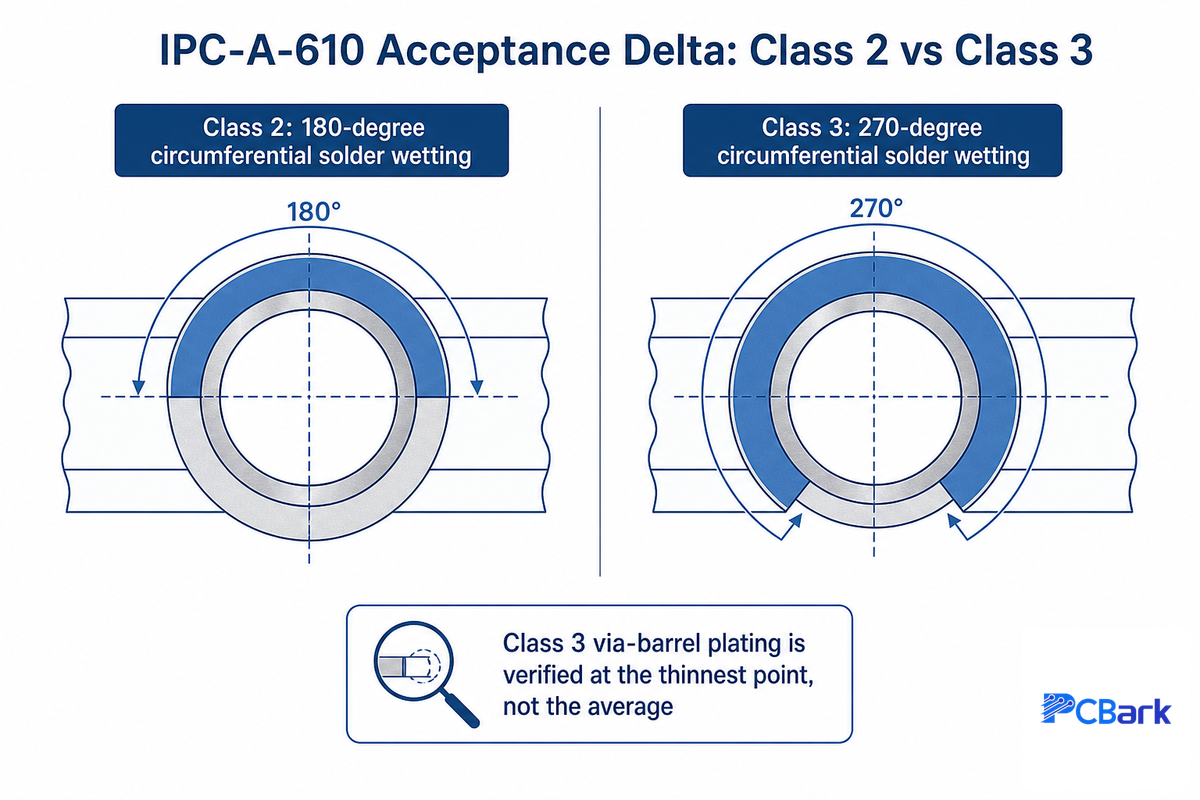
IPC-6012, published by IPC (the electronics industry standards organization), outlines the requirements for rigid printed circuit boards, including aluminum ones. IPC-6012 has three levels of quality: class 1 (general consumer applications where a failed board won’t be costly); class 2 (dedicated service applications, where a board will likely have a useful life but a failed board won’t be considered catastrophic); and class 3 (high reliability applications for consumer and commercial equipment, medical devices, automotive, avionics, etc.). Class 3 boards have a higher level of requirement for things such as conductor spacing, width, annular ring size, and plating compared to Class 2; this results in higher costs and longer inspections.
It’s worth knowing that IPC-6012 performance class is a separate question entirely from a safety listing. UL 796, most recently revised November 2025, covers flammability and safety-construction of PWBs. Metal base PCB requirements are separately called out within UL 796 and there’s a true UL Certification (E301197) that’s specific to a single-layer metal base PCB. Meeting IPC-6012 class 2 or class 3 requirements don’t satisfy UL 796. If your product must have UL Recognition you need to have your manufacturer verify separately for both the IPC and UL standards.
Only select Class 3 if your application really needs it; the increased tolerances will incur an extra cost and add a longer lead time for the design compared to a lower-consequence design on Class 2. The common mistake, born from an overabundance of caution rather than a real requirement, is specifying Class 3 by default for every project; PCBark’s quoting process pushes back on that assumption specifically, asking which failure consequence the design actually carries before pricing the tighter tolerances, because paying for aerospace-grade inspection on a general-purpose LED driver is a budget gap most engineering managers would rather avoid.
[Named Hook] The 4-Question Aluminum PCB Fit Test
![[Named Hook] The 4-Question Aluminum PCB Fit Test — PCBark](https://pcbark.com/wp-content/uploads/2026/07/aluminum-metal-core-pcb-guide-h2_08-1.png)
For: Engineers deciding before they spec a board
Run your design through four rapid-fire questions before committing to a metal-core. Answering “yes” to two or more questions should strongly suggest that an aluminum PCB would be an appropriate selection rather than an added perk.
- Power density: Is a component or cluster of components producing enough heat to necessitate an external heat sink in a standard FR4 layout with a sufficient number of vias and pour area?
- Ambient temperature: Is the application being installed within an enclosed cabinet or environment where passive convection is restricted?
- Component lifespan expectation: Does the application have a projected lifespan of many years, such as that required in LED lighting or the automotive sector?
- Budgetary ceiling: Does the application design have any budgetary flexibility for an increased cost per-board to reduce the requirement for a separate heat sink and its assembly cost?
Two or more “yes” answers indicate that an aluminum PCB is suitable; one or no “yes” answers indicate that a well-designed FR4 PCB with thermal vias would be more cost effective. The stakes behind question three are real: a patent on driving-current control for MCPCB-carried LEDs notes that once metal-core parts age out of production, a luminaire built around an obsolete carrier can become difficult to service years down the line, which is exactly the kind of long-service-life consideration question three is designed to surface before the design is locked in. Aluminum PCBs are appropriate for cases when a metal core PCB is required to support physics, not merely marketing buzz. A common mistake is skipping this test entirely and defaulting to whichever material the last project used, because that shortcut hides a real risk: a board sized for a 1W LED driver doesn’t scale linearly to a 5W cluster, and by the time the thermal problem shows up in the field, the tooling and layout are already locked in. PCBark runs this same four-question check with new customers before quoting, specifically to catch that mismatch before it becomes an expensive redesign.
What Drives Aluminum PCB Cost (and How to Get an Accurate Quote)
For: Procurement and engineering teams requesting quotes
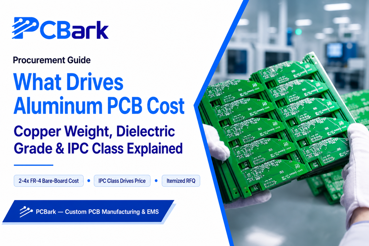
Aluminum PCBs cost more than the equivalent FR4 boards, so it’s fair to state that. Industry prototype pricing for a 10×10” board can range from about $80-200+ compared to approximately $20-50 for FR4, and this is a guideline for prototype volumes, not a quote, because pricing varies based on copper weight, dielectric specs, and order volume.
When asking your manufacturer for a quote, the three primary cost drivers you should consider are copper weight, dielectric material, and thickness, as well as IPC-6012 class. A design that eliminates the need for a separate heat sink and assembly labor will likely be able to absorb much of the extra board cost; this explains “aluminum PCBs aren’t always cheaper”-you must look at total assembly costs, not just the PCB cost.
Ready to spec a board? See PCBark’s aluminum PCB manufacturing capabilities for tiered specs and a project-specific quote.
Industry Outlook: Why Buyers Are Searching Differently for Metal-Core PCBs
For: Engineering managers and buyers tracking the category
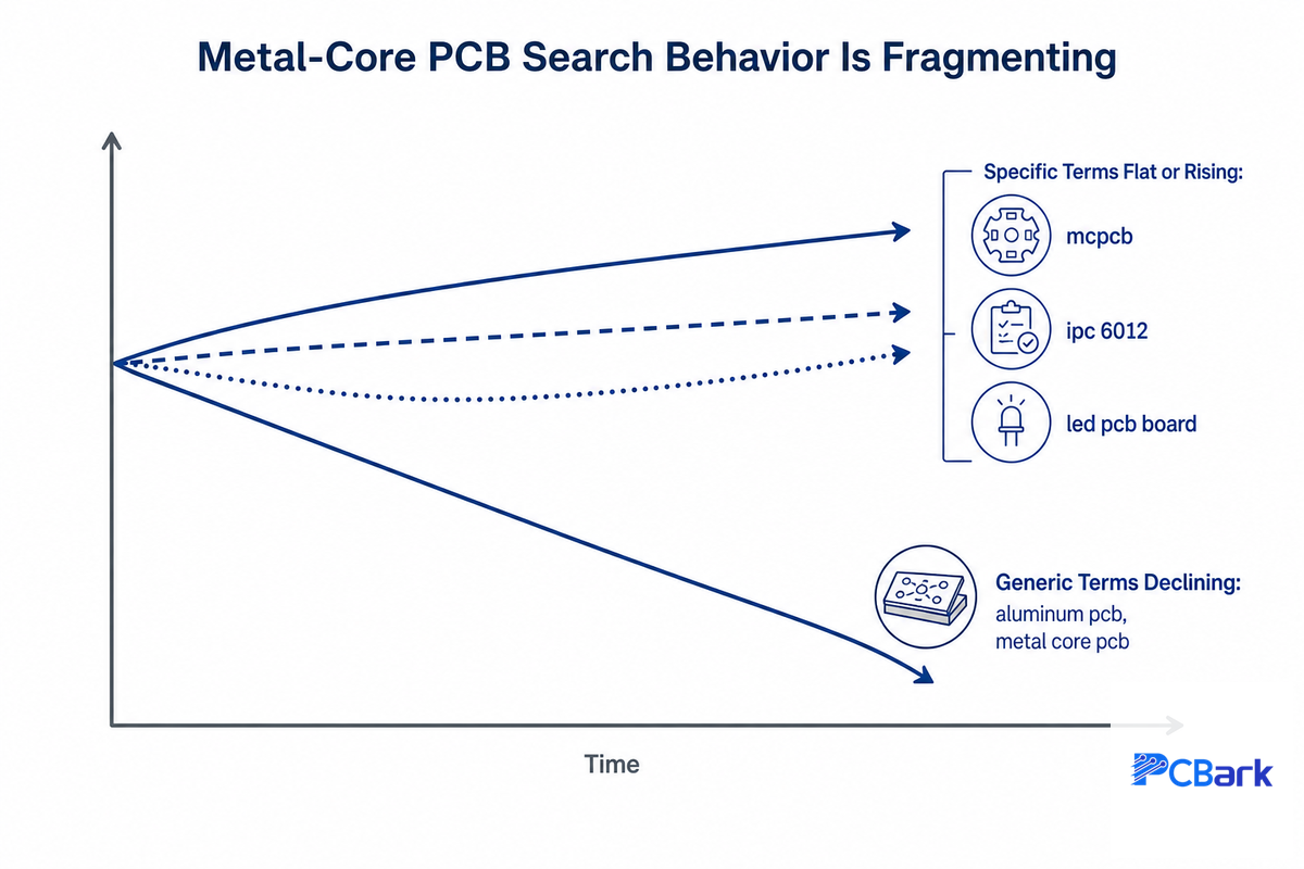
Interest in this category isn’t consolidating; it’s fragmenting. The general descriptive terms “aluminum pcb” and “metal core pcb” are down in search volume year-over-year, while the bare acronym “mcpcb”, the specific standard “ipc 6012”, and application-based terms like “led pcb board” are flat or up. Read together, that pattern suggests buyers are more often landing on a specific decision point — a standard, an application, a comparison — rather than using a general descriptive search term. For a supplier, this means a content and capability page focused solely on “aluminum pcb” is going to miss more specific searches that are actually driving purchasing decisions.
On the technology side, there are two trends to watch closely into 2027. Firstly, IPC is coming out with an IPC-6012 Space Addendum to establish dedicated specifications for aerospace-grade metal-core boards rather than treating these on a case-by-case basis. Secondly, gallium nitride (GaN) power devices are pushing thermal design past what a standard metal-core PCB alone can handle. A 2025 patent filing (US20250081328A1) makes this explicit: it describes GaN switching devices generating enough concentrated heat that a conventional insulated-metal-substrate board becomes a bottleneck rather than a solution, and proposes a copper-inlay PCB paired directly with a heatsink and an L-shaped metal plate instead. That’s a useful signal for anyone specifying boards for next-generation power semiconductors: metal-core PCB is still the default for LED and general power-electronics designs, but the highest power-density GaN and silicon-carbide applications are already outgrowing it toward hybrid inlay and direct-heatsink architectures.
The market size for this category will vary across research providers – numbers ranged from about $2.25 billion to $3.2 billion base year and CAGRs of 6.4% to 9.68% – so treat any individual number as background rather than gospel. With over 16 years of electronic manufacturing and a production capability of 500,000 square meters per year, the size and breadth of our business at PCBark show that the metal core PCB market has matured beyond an LED-driver niche into a default thermal-management choice for lighting fixtures, automotive electronics, and power converters alike.
“The question we hear most from new customers isn’t ‘what is an aluminum PCB’ anymore, it’s ‘which class, which dielectric spec, and which standard do I actually need for my application.’ That shift toward specific, standards-anchored questions is exactly what the search data shows industry-wide.”
Aluminum PCB FAQ, Common Buyer and Engineering Questions
Q: What is an aluminum PCB (MCPCB)?
View Answer
An aluminum PCB, more precisely a metal core printed circuit board (MCPCB), replaces the usual FR4 fiberglass base with a solid aluminum layer. A thin thermally conductive dielectric sits between that base and the copper circuit layer, so the board insulates electrically while letting heat move down into the metal instead of pooling under hot components. Engineers reach for it whenever an LED, power converter, or motor driver would otherwise overheat.
Q: Do all aluminum PCBs contain copper?
See Answer
Yes. Every aluminum PCB still uses a copper circuit layer on top, exactly like a standard FR4 board — aluminum only replaces the fiberglass base underneath, not the conductive traces. What changes is what sits beneath that copper: instead of resin-soaked glass fiber, there’s a dielectric layer bonded directly to a solid aluminum (or sometimes copper) base, which is what gives the board its heat-spreading advantage.
Q: What’s the difference between copper-core and aluminum-core PCBs?
View Answer
Copper conducts heat noticeably better than aluminum, so a copper-core board pulls heat away faster and tolerates higher power densities — but copper is heavier and more expensive, which is why most designs default to aluminum unless the thermal load specifically demands copper’s extra headroom. In practice, aluminum handles the large majority of LED and general power-electronics designs, while copper core is reserved for the hottest, most power-dense boards.
Q: Is FR4 or aluminum cheaper for a PCB?
See Answer
FR4 is a less expensive material on a per-board basis. Aluminum PCBs have higher per-board costs due to the addition of a metal core and bonding process, but it’s often cheaper overall if the thermal limitations of FR4 require you to build larger PCBs, add extra heat sinks, or suffer costly failures.
Q: Are aluminum PCBs harder to fabricate or assemble?
View Answer
Somewhat, yes. Aluminium PCBs are normally single or double sided rather than deep multi-layer, since a true multi-layer stack on solid metal is hard to build, limiting design options from the start. Drilling and routing also vary, since metal doesn’t cut like fibreglass. On assembly, the same fast heat transfer that makes the board useful can cause tombstoning during reflow, so assemblers often customise their reflow profile instead of reusing a generic FR4 one.
Q: What does IPC-6012 Class 2 vs Class 3 mean for an aluminum PCB?
See Answer
IPC-6012 Class 2 applies to general-purpose electronics where minor dimensional or cosmetic deviations are tolerated, while Class 3 applies to high-reliability components in automotive and medical equipment, where tighter controls on annular ring, plating, and inspection tolerances are enforced. Class 3 aluminium PCBs cost more and take longer to inspect, so confirm which class your design actually needs. IPC-6012 classification is also separate from UL 796 listing.
Q: How thick is a typical aluminum PCB dielectric layer?
View Answer
The thickness of the dielectric layer of a typical aluminium PCB varies from around 0.003in to 0.006in (75 to 150µm), with variations dictated by electrical voltage isolation required, thermal properties and specific material choices (thicker dielectric withstands higher voltage but transfers less heat). Always clarify with your aluminium PCB supplier the specific dielectric thickness and its associated thermal conductivity rating.
Why We Write This
At PCBark we manufacture a range of aluminum and other metal-core PCBs alongside Ceramic, Flex, Rigid-Flex, and Rigid boards within a production facility of 500,000sqm/yr and our guide incorporates typical questions from our customers in our sales and engineering departments when considering metal-core PCBs for the first time. Prepared by PCBark Electronic Manufacturing Services Technical team.
References & Sources
- Effect of solder void on mechanical and thermal properties of flip-chip LED assemblies on aluminum PCB — U.S. National Library of Medicine (PMC)
- Aluminum PCB in cryogenic sensor package instrumentation — Fermi National Accelerator Laboratory (Fermilab), U.S. Department of Energy
- IPC-6012: Qualification and Performance Specification for Rigid Printed Boards — IPC (electronics.org)
- UL 796: Printed Wiring Boards (Revision, November 2025) — UL Standards
- Thermal Comparison of FR-4 and Insulated Metal Substrate PCB for GaN Inverter (TIDA030) — Texas Instruments
- Hot tips on thermal management for LED lighting — EDN Magazine
- Thermal Management Strategies for Long-Lived Vehicle Lighting — EE Times
- Power electronic substrate — Wikipedia
- US20250081328A1, Circuit assembly including gallium nitride devices — USPTO / Google Patents (2025)