Get in touch with PCBark Company



Updated June 2026 · Reviewed by the PCBark aerospace engineering team.
An aerospace PCB is a printed circuit board built and accepted to IPC Class 3 – the high-reliability tier designed to thrive against the vibration, thermal cycling, low pressure, and radiation of flight environments that a normal commercial board is never qualified for. In aerospace and defense, in avionics, satellites, and unmanned systems, printed circuits endure extreme temperatures and forces that demand a durability ordinary consumer electronics never need. Here’s a walkthrough of how aerospace PCBs are designed, which materials and construction are appropriate for each application, how IPC Class 3 work crosses commercial work in measurable microns, and the one topic everyone else misses: which standard your program actually needs, and what factors truly influence your quote.
Quick Specs: Aerospace PCB at a Glance
| Build acceptance | IPC-6012 & IPC-A-610 Class 3 (IPC-6012FS for space) |
| Core materials | High-Tg FR-4, polyimide, ceramic, Rogers / Megtron RF laminates |
| Board types | HDI (up to 32 layers), rigid-flex, RF/microwave, metal-core |
| Min. hole-wall copper | 25 µm (1 mil) Class 3; 38 µm typical for thermal-cycled flight hardware |
| Controlled impedance | ±5% (vs ±10% commercial) |
| Electrical test | 100% flying-probe / ICT, not lot sampling |
What Makes a PCB “Aerospace-Grade”?

An aerospace PCB receives its label by being qualified to operate where it’s unable to be repaired. Commercial boards are operated in climate-controlled rooms; flight hardware encounters roughly −55 °C to +125 °C, vibration profiles of 10 Hz to 2,000 Hz, and low-pressure operation above 50,000 feet.
Three factors distinguish an aerospace printed circuit board from a typical design: it’s accepted to IPC Class 3, it makes use of high-reliability material systems and finishes, and it maintains documented traceability from copper foil to final test. Sound aerospace PCB design starts by classifying the aerospace environments a board will see and the assembly process it must survive, because the same layout behaves quite differently across aerospace applications, a satellite payload and a cabin display share a standard but not a stress profile.
This piece of the certification program trips up users more than anything else: “aerospace” isn’t a blunt instrument. The proof stack vary depending on the environment faced by the hardware, and using the wrong set of requirements is what ruins a qualification – and derails a commercial claim.
| Mission segment | Baseline board acceptance | Added qualification layer |
|---|---|---|
| Commercial aviation / avionics | IPC-6012 Class 3, ISO/AS9100 | RTCA DO-160 environmental, DO-254 hardware assurance |
| UAV / drone electronics | IPC Class 3 + traceability | Weight / vibration screening (often no AS9100 gate) |
| Satellite / NewSpace | IPC-6012FS space addendum | Outgassing control, 15–20 yr life, thermal-vacuum |
| Defense / military | IPC Class 3 + MIL-PRF-31032 | ITAR / export control, DLA QML, AS9100 |
Read that table as a map of this guide. The fabrication floor, plating, dielectric, impedance, materials, is shared. What changes between a commercial aerospace PCB and a defense build is the qualification and export layer stacked on top, which we untangle below.
Why Aerospace PCBs Fail, and the Design Responses That Prevent It
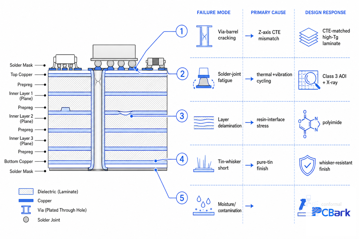
Space hardware seldom malfunctions because a trace was a few microns narrower than necessary. Space hardware is at risk at the via barrel, the solder joint, and the laminate interface – physical fatigue effects which grow with each hundreds or thousands of thermal and vibration cycling.
The dominant mechanism is plated-through-hole barrel cracking driven by Z-axis CTE mismatch. Peer-reviewed analysis of copper-plated through holes shows that the mismatch between copper (~17 ppm/°C) and the laminate drive thermal-fatigue cracking, and that empty or solder-filled holes crack more readily under greater CTE-mismatch strain. Thermal fatigue research on Cu-plated through holes ties the failure directly to that strain. The most direct design defense is matching the Z-axis CTE of the laminate to the conductors, an approach documented in USPTO patent US8203080B2 for CTE-matched build-up cores.
The 5-Mode Flight-Hardware Failure Map
| Failure mode | Root cause | Design / process response |
|---|---|---|
| Via-barrel cracking | Z-axis CTE mismatch over thermal cycles | CTE-matched high-Tg laminate; 25–38 µm capped barrel copper |
| Solder-joint fatigue | Coupled thermal + vibration cycling | Class 3 acceptance; AOI + X-ray on every joint |
| Layer delamination | Resin-interface stress at high temperature | High-Tg FR-4 or polyimide systems |
| Tin-whisker shorts | Pure-tin / lead-free finish growth | Whisker-resistant finishes; conformal coating coverage |
| Moisture / contamination | Humidity, salt fog, service exposure | Acrylic / parylene conformal coating; low-outgassing laminate |
Tin whiskers deserve their own line because they’ve actually downed flight hardware: NASA’s electronic-parts reliability program links pure-tin whisker growth on printed-wiring-board traces to in-orbit failures, including the complete loss of the Galaxy IV satellite. NASA NEPP metal-whisker research documents the mechanism. It’s the reason a lead-free finish that’s fine for a phone is a liability on a board that has to fly.
📐 Engineering Note
Specify a laminate with Z-axis CTE below ~70 ppm/°C and Tg above 170 °C to limit barrel strain, then ask the fabricator for capped barrel copper of 25–38 µm. The single most useful question for any aerospace PCB program isn’t “are you Class 3?” but “show me the actual measured plated-thickness distribution from your last build” — nominal process specs and real statistical capability aren’t the same thing.
Aerospace PCB Materials: FR-4, Polyimide, Ceramic & RF Laminates
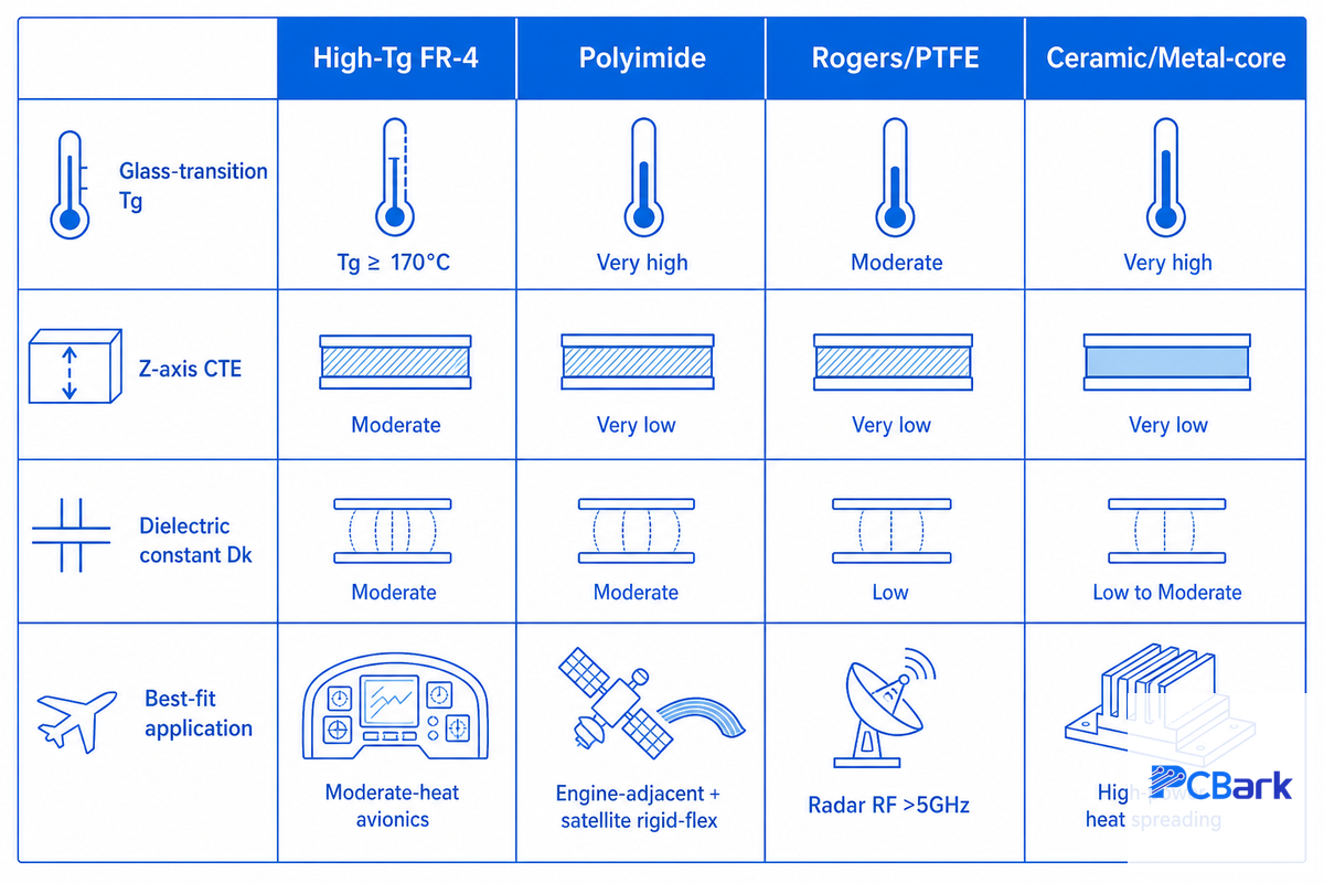
Material selection is where aerospace boards earn their reliability, and where buyers most often over-specify. The honest engineering view is that the laminate follows the thermal and signal demand, not a blanket “polyimide is the aerospace material” rule.
What materials are used in aerospace PCBs?
Aerospace laminates run from high-Tg FR-4 through polyimide to ceramic and PTFE/Rogers RF systems. Polyimide handles continuous high-temperature exposure without delaminating, which makes it the default for engine-adjacent avionics and weight-critical rigid-flex. High-Tg FR-4 (Tg ≥ 170 °C) is a cost-effective alternative that performs well under moderate heat.
PTFE and Rogers laminates (such as RO4003C) are reserved for radar and electronic-warfare boards where signal integrity above 5 GHz is non-negotiable, and ceramic or metal-core substrates carry high-power, high-heat loads. The contrarian point worth internalizing: over-specifying polyimide on a moderate-heat board buys cost, not reliability.
| Material | Key property | Best fit |
|---|---|---|
| High-Tg FR-4 | Tg ≥ 170 °C, low cost | Moderate-heat avionics, controllers |
| Polyimide | High Tg, low outgassing, flex-stable | Engine-adjacent, satellite rigid-flex |
| Rogers / PTFE | Controlled Dk, low loss > 5 GHz | Radar, comms, telemetry front ends |
| Ceramic / metal-core | High thermal conductivity | High-power drivers, heat spreading |
Surface finish matters as much as the core. ENIG and ENEPIG give reliable solderability and shelf life, and conformal coatings, acrylic, silicone, urethane, or parylene, protect against moisture and outgassing. Surface finishes and PCB finishing choices interact with the laminate’s glass transition temperature, its heat dissipation behavior, and how the PCB stack-ups hold up over repeated thermal cycles in extreme environments. Aerospace work favors ENIG and ENEPIG over hot air solder leveling, and flex and rigid-flex PCBs that must withstand extreme conditions across PCB aerospace and defense programs lean on whisker-resistant systems; the same discipline applies to military and aerospace PCBs. Map your stack-up to a build with PCBark’s aerospace material and standard selector before committing to a laminate.
Board Types for Aerospace: HDI, Rigid-Flex, RF & Metal-Core
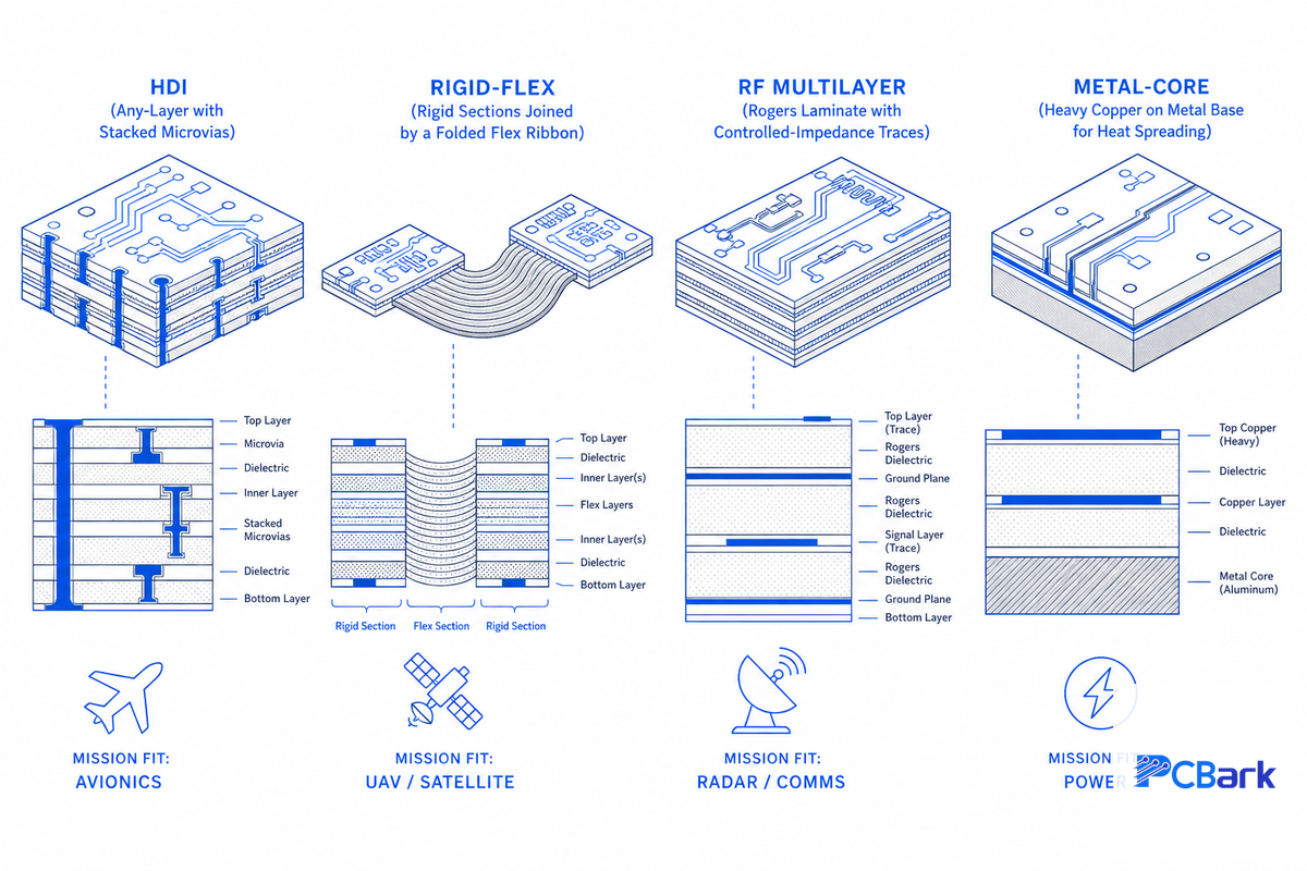
No serious aerospace product uses a single board technology. A drone flight controller, a satellite payload, and a radar front end pull in different directions, weight, signal integrity, thermal dissipation, and the board type follows the mission priority. Using the wrong technology wastes weight, fails qualification, or forces a redesign.
The 9-System Board-Type Matrix
| System type | Priority | Recommended board | Why |
|---|---|---|---|
| Avionics compute module | I/O density | Any-layer HDI | Fine-pitch BGA, 0.050 mm laser vias, Class 3 |
| Flight-control / display board | Density + reliability | HDI | I/O density without losing Class 3 acceptance |
| UAV / drone flight controller | Weight + density | Rigid-flex + HDI | Removes connectors, cuts mass |
| Drone payload / camera | Flex + low mass | Flex / rigid-flex | Bends into tight airframe volume |
| Satellite bus | 15–20 yr life | Polyimide rigid-flex | Bend-tolerant, thermal-stable, low outgassing |
| NewSpace payload | Low mass, fast build | Rigid-flex, polyimide | Weight-critical, quick-turn; 100,000+ bend cycles |
| Radar front end | Signal integrity | RF multilayer (Rogers) | ±5% impedance control above 5 GHz |
| Comms / telemetry | Low loss > 5 GHz | RF multilayer (Megtron) | Controlled dielectric constant, low loss |
| Power / actuator board | Thermal dissipation | Metal-core / heavy copper | 6 oz copper, heat spreading |
Rigid-flex earns its place on UAVs and satellites because the format is intrinsically space-saving: a folded board take minimal volume and removes costly high-pin-count interconnects, which are themselves a vibration failure point. Field practitioners put it plainly, harden the design for vibration and mount the board on a damper system, because component values themselves shift at temperature extremes. Most weight-critical aerospace work today lands on rigid-flex and HDI aerospace PCB fabrication, which is the direction NewSpace and drone demand keeps pushing. Whatever the board type, thermal management and power distribution shape the layout as much as signal routing, and across aerospace industries, the boards that survive extreme conditions are designed for them from the first stack-up, not retrofitted later.
IPC Class 3 vs Class 2: The Reliability Gap, Measured in Micrometers
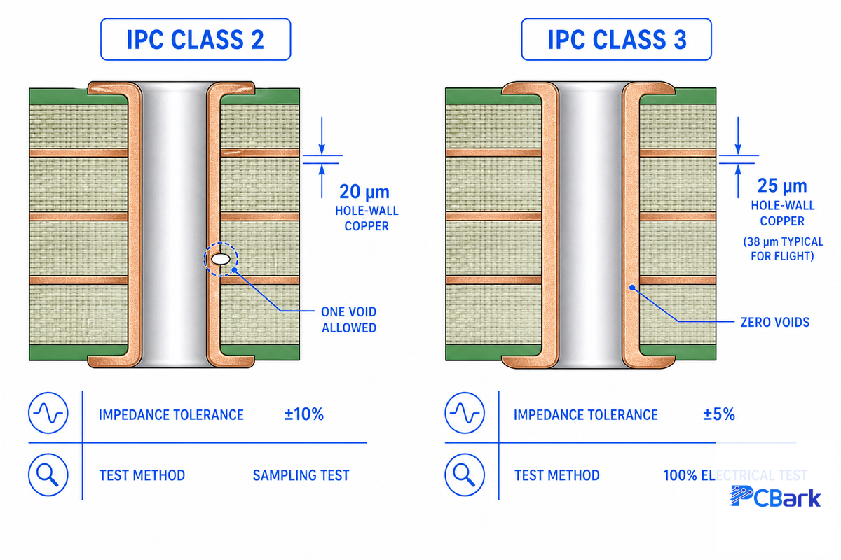
“High Reliability” becomes real only at micron resolution. You achieve it via IPC-6012 Class 3, the standards that qualify you between commercial and flight. The difference between Class 2 and Class 3: microns and percentages not prose.
| Attribute | Commercial (Class 2) | Aerospace (Class 3) |
|---|---|---|
| Min. hole-wall copper | 20 µm | 25 µm (38 µm typical for flight) |
| Copper voids in barrel | 1 void per 5% of holes | Zero voids |
| Internal annular ring | 25 µm (1 mil), 90° breakout tolerated | 50 µm (2 mil), no breakout |
| Impedance tolerance | ±10% | ±5% |
| Electrical test | Lot sampling common | 100% test expected |
Those numbers come from the IPC-6012 standard, not from any single fabricator. IPC-6012 and its space addendum (IPC-6012FS) define them. The practical takeaway for procurement: many qualified shops can hold ±10% impedance but not ±5%, and the gap between the 25 µm spec floor and the 38 µm flight hardware actually buys is exactly where reputations are made. These performance requirements apply across the PCB, not just at signal lines, and define what qualifies a board for aerospace use. Compare a specific build with PCBark’s IPC Class 2 vs Class 3 comparator.
ITAR, AS9100 & IPC Class 3: Which Standard Does Your Program Actually Need?
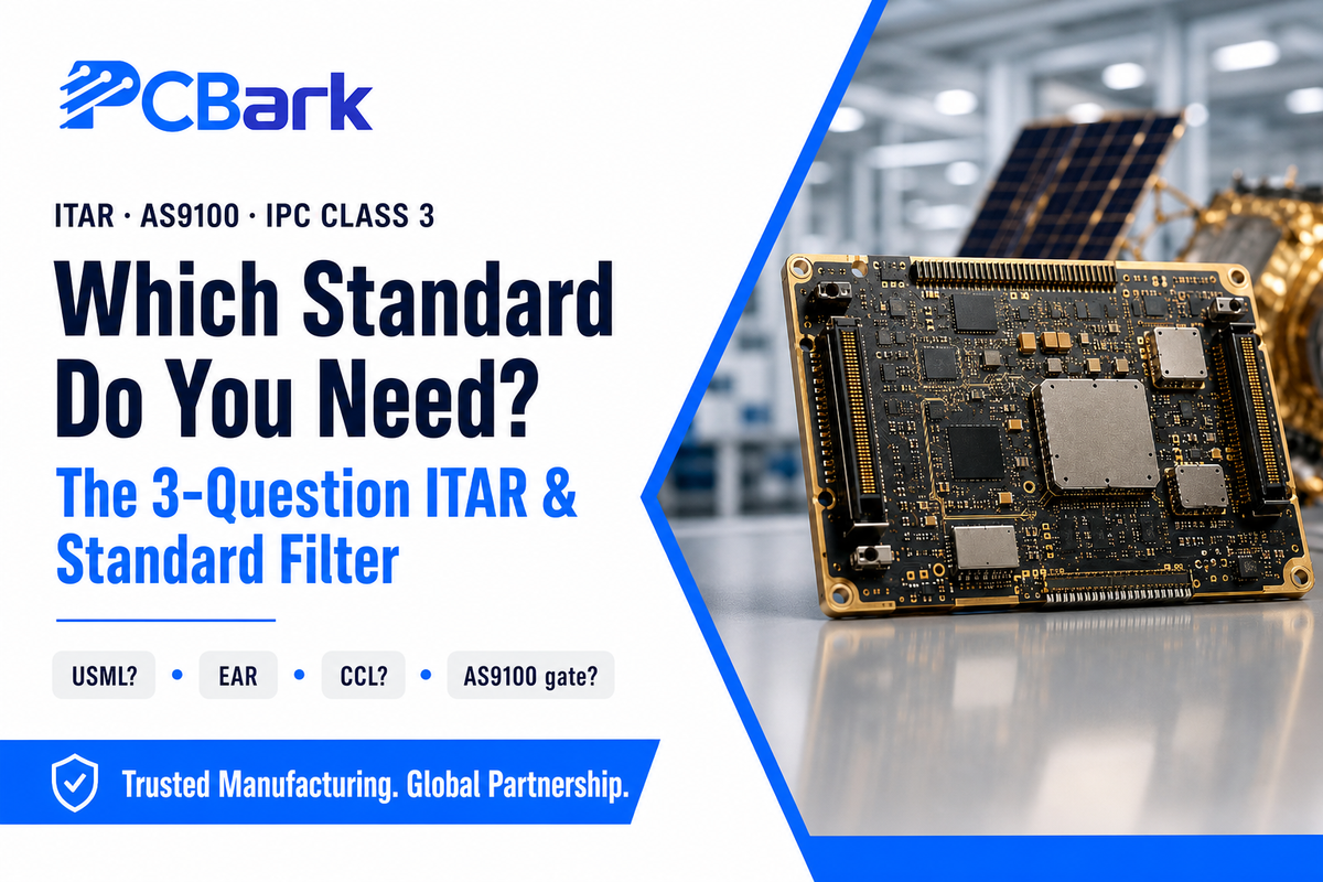
Buyers routinely overpay for an ITAR-registered U.S. fab they do not need, or get rejected by one they do, because nobody draws the line clearly. ITAR is the International Traffic in Arms Regulations, and it governs defense articles, not commercial boards by default. So here is that line, stated plainly rather than buried in a footnote, as three questions any program can answer.
The 3-Question ITAR & Standard Filter
- Does the target product fall on the U.S. Munitions List? If it does, and you want a custom design for that specifically, your job has to stay in an IT AR-registered facility in the US.
- If your part isn’t USML-related, do you also need to be worried about Commerce Control List (ECCN)? This control is more widespread than ITAR; and applies to exports to and from the US.
- Will you’ve to onboard an AS9100 supplier for the project? It’s common for aerospace OEM purchasing to make AS9100 compliance a condition of procurement irrespective of actual PCB capability.
Are aerospace PCBs required to be ITAR compliant?
No – it isn’t a given that you’re covered if a job isn’t classified for ITAR. ITAR applies to defense articles on the USML; a printed circuit board is only covered if it’s specifically designed or modified for them (22 CFR Category XI), according to the U.S. State Department’s Directorate of Defense Trade Controls. Generally, commercial aviation, commercial UAV, and NewSpace applications aren’t controlled by ITAR.
For that work, IPC Class 3 acceptance, traceable material genealogy, and (if the contract requires) AS9100 certification protects the program. A key, and frequently unmentioned, caveat is that the non-ITAR status of a program isn’t the same as being free from export control: the EAR and Commerce Control List can apply and you need to determine the specific classification.
There’s two types of standards that can easily get conflated. The first, AS9100D – SAE AS9100D – is a quality-management system based on ISO 9001, with the added benefits of counterfeit part detection and prevention, configurations control, and first article inspection. The second, IPC-6012 Class 3, defines the requirements for a physically sound circuit board; a facility does not need to have AS9100 certification to meet the Class 3 requirements. These industry standards govern qualification and performance differently: across military and aerospace programs MIL-PRF-31032 and AS9100 add audit and qualification layers, while IPC Class 3 is the baseline acceptance that every reliable aerospace PCB must meet first. The standards for military and aerospace applications sit on top of that baseline: MIL-PRF-31032 governs circuits for aerospace and defense, AS9100 covers aerospace and military programs, and the electronic systems in aerospace applications they qualify — flight control, comms, radar — all trace back to the same bare-board acceptance, which is why PCBs for aerospace earn their reliability at the fabrication layer first.
“We tell aerospace buyers the same thing every time: if your program is ITAR-controlled, use a registered U.S. fab, full stop. If it is commercial aviation, a drone, or a NewSpace payload, what protects you is Class 3 acceptance and a traceable material genealogy, and that is exactly what we document on every board.”
PCBark Aerospace Engineering Team
PCBark purposely remains on the commercial and civil side; they accept for Class 3 according to IPC-6012 and IPC-A-610, under a IATF 16949 quality system based on ISO 9001. Their specialty avionics, UAV, satellite/NewSpace and global export work isn’t ITAR-registered or part of a defense AS9100 onboarding process. If your RFQ specifies AS9100 onboarding or ITAR registration, know it’s a valid requirement, and you need to source it to a properly registered U.S. shop. Not sure which applies? Run it through the aerospace PCB RFQ readiness checklist.
Quality, Testing & Traceability for Flight Hardware
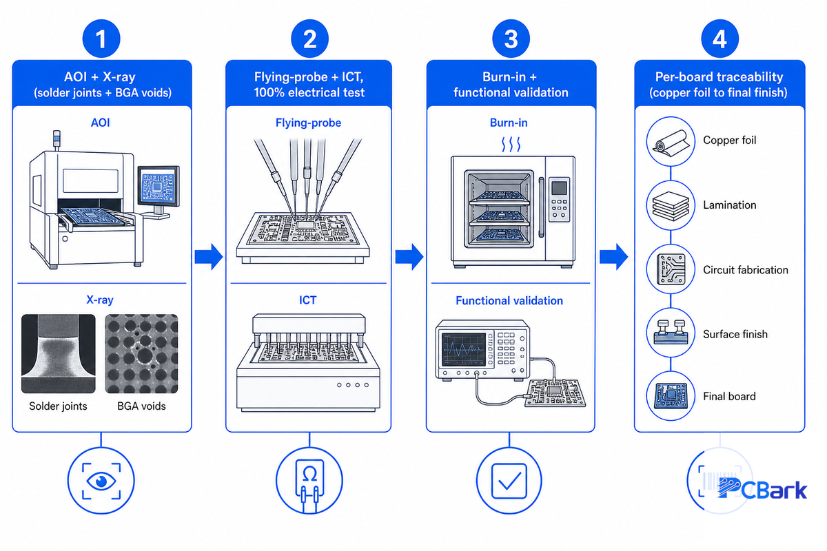
A certification says that you can initiate a discussion with that supplier, but not necessarily that the hardware is ready for production. You could have a supplier that successfully passes quality audits but lacks the necessary capabilities and experience to meet precisely tuned plating thickness and impedance limits for your flight electronics. For this reason, the traceability stack – and the resulting audit trail – should be your focus rather than the logo on your supplier’s certificate. Good PCB designers and the designers and manufacturers behind them document the environmental conditions each assembled PCB is built for, down to the minimum thickness of every plated feature, so the record matches what actually shipped.
- AOI and X-ray scans performed on both the internal structure and solder joints – this includes measurements on voiding and the dimensions of any internal cavities under BGA components.
- Flying probe and In-Circuit Testing (ICT) will ensure 100% electrical validation – no reliance on sampling.
- Burn-in and functional testing are used to ensure the product operate reliably and meets specification under the same stresses the finished device will face.
- Traceability reports will follow each individual board from its first copper foil to the final coating process, detailing material lots, processing data and all test results along the way.
The design process becomes real during environmental qualification. MIL-STD-810H methods cover temperature shock (503.7, −55 °C to +125 °C), random vibration (514.8, 10 Hz–2,000 Hz), mechanical shock (516.8), and altitude/humidity (500.6/507.6). The standard is tailored to the platform, a flight controller in a pressurized cabin runs a different profile than an exterior sensor array. The traceability discipline that backs it, from Certificate of Compliance down to copper-foil mill certs, is what lets you isolate a field failure to a specific production lot. PCBark documents this chain on every aerospace PCB assembly under ISO 9001 and IATF 16949, the practical, non-defense equivalent of the same audit logic.
Sourcing Aerospace PCBs: Lead Times, Cost Drivers & RFQ Readiness

Low headline pricing obscures actual costs. procurement will often see an attractive price for what the buyer thinks will be fully fabricated PCBs, only to find the tooling, test, and shipping cost additional. Worse still, many waive the electrical testing in exchange for lower unit prices, ultimately forfeiting the value they’ve paid for if the faulty bare PCB is discovered in a final unit. High unit costs driven by defects and excessive vendor-management costs can far outweigh the low unit price on your cost analysis.
What actually drives your aerospace PCB quote
- Depth of testing versus board class – i.e., Class 3 vs 2, 100% test versus random sampling.
- Choice of core material and construction ( Rogers vs. FR-4 vs. polyimide) along with the finish.
- Turn time, volume of build, and speed. (Quick-turn prototyping vs mass production.)
- Sourcing model, turnkey, partial turnkey, or consignment.
- Level of mandated compliance requirements ( ITAR, AS9100). Higher compliance levels reduce the field of potential suppliers and can inflate costs independent of board specifications.
Lengthy leads correlate to complexity. Turnkey fabrication is typically completed 1-15 business days after receipt of the customer’s production data; however, PCBs manufactured in a facility certified to the DLA Qualified Manufacturers List underMIL-PRF-31032 require about 12 to 18 months of qualification before the first boards roll off the line. You need to understand where in this timeline you stand for each piece of business so you can estimate accordingly. Ask suppliers to quote your parts line by line rather than as a sum; this allows you to pinpoint precisely where costs are going. When you compare an aerospace PCB manufacturer, look past the headline at the real PCB production capability and aerospace PCB manufacturing controls behind the quote: a manufacturer that owns fabrication, assembly, and test as one supply chain under a single ISO 9001 quality system ships more consistent PCB solutions than one that brokers PCB requirements across vendors.
What’s Changing in Aerospace PCBs (2026 Outlook)

The single, most important business decision that must be made in regard to electronic assemblies for 2026 isn’t about the growth rate; rather, it’s about selecting the appropriate board technology on which the next round of products should be based, qualified, and shipped without a costly redesign.
NewSpace and unmanned aerial vehicle programs are putting a lot of pressure toward lightweight, rigid-flex boards and anywhere/any layer HDI designs. For those products, the design for any/all layers is going to come at the earliest stages of the project, and may include bend radius calculations and laser-via specifications. Industry forecasts put the rigid-flex segment near a 9.5% CAGR against a low-to-mid single-digit rate for aerospace PCBs overall, which is the clearest signal that miniaturized, connector-eliminating construction is where qualification effort is heading. A typical example: a NewSpace startup that began on rigid FR-4 hit mass and connector-reliability limits on its second satellite revision and re-specified to polyimide rigid-flex, cutting wiring mass and removing the high-pin-count connectors that had failed vibration screening.
Standards-wise, the public milestone move incidentally: IPC-6012 Revision F is the newest version of the high-rel qualification standard, and IPC-6012FS officially upgrades Class3 qualification specifically for space and military avionics. The concrete action is known: mentioning IPC-6012FS explicitly in the RFQ rather than a generic “Class3” when you’re buying for a space or NewSpace payload in 2026 is no more trouble than having an alternate way of saying “please build to the addendum,” rather than simply confirming your fabricator does. market size data (low-to-mid single digit CAGR for aerospace PCBs generally) is context; the purchasing incentive is the transition to rigid-flex plus the space addendum tightening. The advanced technologies pulling at this market, denser communication systems, autonomous aerospace systems, and high-reliability applications that must hold up under extreme operating conditions, all reward buyers who specify the board for the mission early rather than late.
Frequently Asked Questions
Q: What is an aerospace PCB?
View Answer
An aerospace PCB is one that is built and proved to IPC Class3, designed to withstand the vibration, temperature cycling, reduced pressure and radiation common to flight conditions. It is different from a commercial board in the choice of materials, the impedance and plating specifications and the documented traceability records linking the finished board to its material test data.
Q: What standards apply to civil aerospace PCBs?
View Answer
Most commercial aerospace (also civil aviation, commercial UAV and NewSpace) boards are constructed to IPC Class 3 (IPC-6012) and loaded onto ISO/AS9100 quality systems, with IPC-6012FS invoked for space. There is no one IPC standard all space boards equal – rather, the precise specification must be separately negotiated and is layered with RTCA DO-160 environmental conditions and DO-254 hardware assurance for the completed element. This means two boards both cited “aerospace Class3” can be very well tested or very poorly, so including the precise standards, addenda, and test procedures into the RFQ is a best practice.
Q: Do aerospace PCBs have to be ITAR compliant?
View Answer
Not automatically. ITAR stipulates only that the board not be specifically designed for a defense article listed on the Munitions List (22 CFR Category XI). Commercial airlines, commercial UAV and NewSpace programs generally are not under ITAR. That said, non-ITAR electronics may be imposed with EAR and the Commerce Control List restrictions, so the classification can safely be known without needs.
Q: What materials are used in aerospace PCBs?
View Answer
High-Tg FR-4 for medium-high heat, polyimide for high temp and rigid-flip, Rogers/PTFE for RF > 5Ghz, or ceramic and metal-core for power heat spreading – picked not automatically simply for being better.
Q: How does AS9100 affect PCB production and the supply chain?
View Answer
AS9100 adds aerospace-specific quality demands to ISO 9001 – counterfeit part countermeasures, configuration control, risk management, and First Article Inspection. For many defense and tier2-suppler programs it is a contractual vendor-onboarding flag, which constricts the qualified vendor set even if a non-AS9100 fabricator can produce the board to IPC Class 3.
Q: Can an offshore manufacturer build reliable aerospace PCBs?
View Answer
For non-ITAR commercial, UAV, civil and NewSpace program work, yes. The board’s reliability hinges on its approval to IPC Class 3, persistent material traceability and documented testing, not on the nation’s label. The all-important rub: any ITAR-controlled defense project must be built at a registered U.S. facility, period.
Why We Wrote This
PCBark builds commercial and civil aerospace PCBs, HDI, rigid-flex, and RF boards accepted to IPC-6012 and IPC-A-610 Class 3 across eight SMT lines. The micrometer specs, failure modes, and the ITAR-versus-Class-3 line in this guide come from the boards we fabricate and the buyer questions we answer every week, including the ones where the honest answer is “for that program, you need a registered U.S. shop, not us.” Reviewed by the PCBark aerospace engineering team.
References & Sources
- IPC-6012FS Space Addendum — IPC (Association Connecting Electronics Industries)
- AS9100D Quality Management Systems — SAE International
- ITAR / USML (22 CFR Category XI) — U.S. State Department, Directorate of Defense Trade Controls
- Thermal Fatigue and Failure Analysis of Cu-Plated Through Holes — Microscopy and Microanalysis
- Metal Whisker Reliability Research — NASA NEPP
- USPTO Patent US8203080B2, CTE-Matched Build-Up Core
- What Is New in IPC-6012 Revision F — Summit Interconnect