Get in touch with PCBark Company

Ferrite Beads in PCB Design: Impedance Curves, DC Bias Derating, and Layout Rules

A ferrite bead is a passive electronic component that limits high-frequency electromagnetic interference (EMI) on printed circuit boards. It works by transforming unwanted high-frequency noise energy into heat in a ceramic ferromagnetic core. In its resistive operating region at high frequencies, a filter ferrite bead dissipates some of the conducted noise energy as heat. This loss reduces the noise that can couple into nearby traces. As discussed in everything RF’s technical overview of ferrite beads, manufacturers typically specify these components by their impedance at 100 MHz. In series with a noisy power supply line, the bead passes normal low-frequency and DC current flow with minimal voltage drop. In a local shunt with a capacitor, it forms a dissipative low-pass filter to reduce noise. The bead can also suppress high-frequency noise on digital supplies. That resistive attenuation limits radio frequency interference (RFI) across board traces.
Selecting the wrong part or positioning it next to an undamped capacitor can destabilize switching power supplies. Engineers routinely find two field failures when troubleshooting industrial electronic equipment. First, as described in Altium’s ferrite bead guide, a high DC load current can saturate the ferrite core and remove up to 90% of its 100 MHz impedance. Second, as described in Analog Devices’ AN-1368 example, a TDK MPZ1608S101A bead and a Murata GRM188R71H103KA01 ceramic capacitor exhibit a 10 dB gain at the ADP5071’s 2.4 MHz ripple frequency. This guide addresses impedance curves and DC bias derating, PDN damping topologies and SMT layout to prevent interference on production cards.
What Does a Ferrite Bead Do on a PCB and How Does It Convert EMI into Heat?
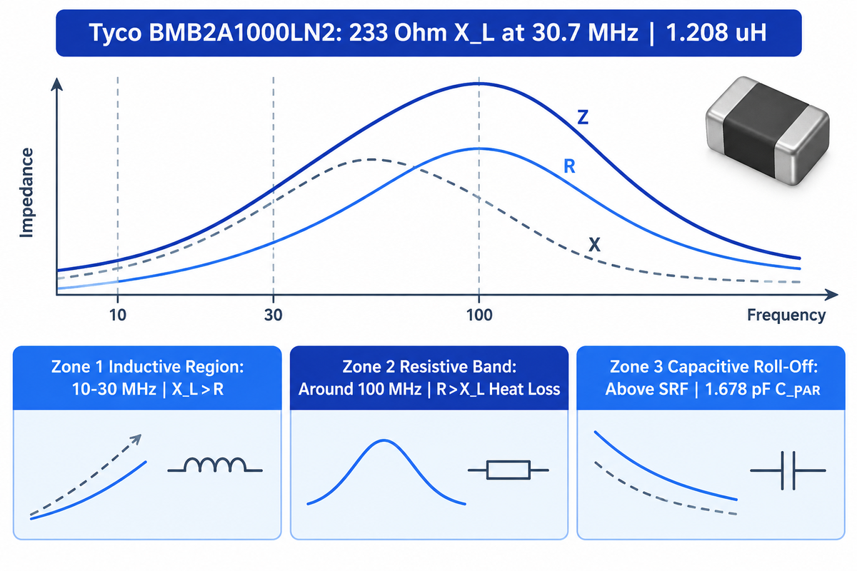
A ferrite bead behaves as a high-frequency noise element through magnetic losses with resistive behavior dominating in the frequency region where its resistance is greater than the magnitude of its reactance. Complex impedance is Z = R + jX, and its magnitude is |Z| = √(R² + X²). Noise energy is dissipated as heat between the crossover frequency and the self-resonant frequency (SRF).
Under the crossover frequency, a coil stores magnetic energy in its magnetic field. Above the crossover frequency, within the iron oxide ceramic lattice there exist magnetic domain walls that dissipate energy as heat. We map this transition using “The 3-Zone Ferrite Impedance Curve” framework. As shown in EDN’s analysis of ferrite bead impedance behavior, inductive reactance dominates around 10–30 MHz and drops near 100 MHz. Meanwhile, resistance R rises to dominate total impedance Z around 100 MHz. In the Analog Devices AN-1368 characterization of the Tyco Electronics BMB2A1000LN2 multilayer ferrite bead, inductive reactance is 233 Ω at 30.7 MHz. The extracted equivalent circuit yields a bead inductance of 1.208 μH and a parasitic capacitance of 1.678 pF. Above the self-resonant frequency (SRF), that 1.678 pF winding capacitance shunts the core and impedance drops sharply.
| Impedance Zone | Dominant Parameter | Typical Frequency Band (BMB2A1000LN2 Benchmark) | Circuit Effect on PCB Noise |
|---|---|---|---|
| Zone 1: Inductive Region | Inductive Reactance (XL > R) | Low frequencies (~10–30 MHz in EDN plot; 233 Ω XL at 30.7 MHz on BMB2A1000LN2) | Stores magnetic energy; can form an underdamped LC network with low-ESR capacitors |
| Zone 2: Resistive Absorption Band | Ferrite AC Resistance (R > XL) | Device-specific band identified from the R-X-Z curves (dominates around 100 MHz per EDN) | Dissipates high-frequency noise as heat |
| Zone 3: Capacitive Roll-Off | Parasitic Capacitance (XC from 1.678 pF CPAR) | Above Self-Resonant Frequency (SRF) | High-frequency noise bypasses the core through inter-layer capacitance |
What is the difference between ferrite mix 31 and 43?
Mix 31 is a manganese-zinc (MnZn) ferrite formulated for lower frequency EMI suppression from 1 MHz to 300 MHz. On the other hand, Mix 43 is a NiZn ferrite material targeting 25 MHz to 300 MHz (extending up to 1 GHz). MnZn grades present higher initial permeability. On the other hand, NiZn grades give higher bulk resistivity.
According to EDN’s material comparison, NiZn ferrites have volume resistivity in the 10³, 10⁶ Ω·cm range. They excel in the 10–100 MHz band and beyond. A 2025 peer-reviewed study on commercial TDK NiZn ferrite beads (PMC12526085) measured magnetic hysteresis loops under applied fields up to ±500 mT at 25 °C. In that test, NiZn flux concentration raised pulse amplitude by 1.5–2.0 times and energy by 30–40%. Those measurements show why NiZn cores must be evaluated under operating magnetic bias. Specific NiZn cable cores can show Curie points down to 135 °C, while RF NiZn mixes exceed 300 °C. Engineers should check the exact material grade datasheet for high-temperature designs.
Ferrite Bead vs. Inductor vs. Common-Mode Choke: Which EMI Filter Component Fits Your Line?
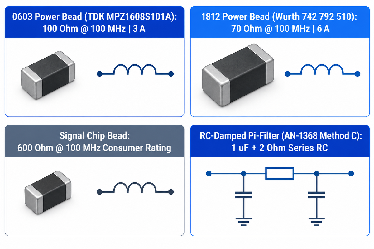
Select a chip ferrite bead to dissipate differential mode noise on a single rail, or a choose an inductor for energy storage and tuned filtering. Common-mode noise on coupled data lines can be blocked by a common-mode choke. A common-mode choke presents an impedance to common-mode noise and allows differential signals to pass.
Although a ferrite bead and a wirewound inductor both contain magnetic cores, their quality factors (Qs) target different outcomes in a circuit. Decreasing Q in a resistive region of a ferrite bead allows for magnetic loss to damp high frequency oscillations and reduce electromagnetic interference. IEC 62024-1:2024/COR1:2025 Edition 4.0 standardizes electrical characteristics and measuring methods for chip inductors in the nanohenry range. Ferrite-bead impedance values follow manufacturer test conditions in a 50 Ω system. Technicians snap a clip-on ferrite core, ferrite clip, or ferrite clamps over a power cord or audio cables to reduce conducted noise. A black clip-on ferrite ring core acts as an external rfi emi noise suppressor cable sleeve. Installers can raise impedance across a broad frequency range by looping the cable around the core. Cable radiation can be dampened by a chokes ferrite core or emi noise suppressor cable clip. The bead clip-on ferrite core rfi clamp in service kits allows field retrofits. An external cable bundle can also be treated with a split ferrite ring core rfi emi sleeve. A molded ferrite core ferrite shell on external leads curbs ring core rfi emi noise. Discrete SMD beads replace external ferrite bead sleeves. Our article on capacitor symbols and polarity markings on PCB schematics separates L inductors from FB beads.
| Component Type & Filter Category | Primary Noise Target | Energy Mechanism | Standard Characterization & Benchmark Spec | Best PCB or Cable Application |
|---|---|---|---|---|
| Low-DCR Power Chip Ferrite Bead (FB) | High-frequency differential mode noise on DC rails | Resistive absorption in the R > XL band | 100 Ω at 100 MHz, 3 A rated DC current (0603 TDK MPZ1608S101A per AN-1368) | 3.3 V / 1.8 V / 1.3 V digital and analog IC supply pins |
| High-Current Power Chip Ferrite Bead | Conducted switching harmonics on multi-amp rails | Magnetic core loss converts high-frequency current into heat | 70 Ω at 100 MHz, 6 A rated DC current (1812 Würth 742 792 510 per AN-1368) | High-current DC-DC pre-regulators and point-of-load feeds |
| General Signal Chip Ferrite Bead | Broadband digital clock and sensor line noise | Resistive attenuation across target harmonic band | 600 Ω at 100 MHz average consumer rating (reported by Industry Research) | Low-current clock buffers, audio codecs, and sensor sub-rails |
| Steep-Curve Digital Chip Bead (BLM_B Type) | Clock harmonics above 100 MHz on digital lines | Low impedance at tens of MHz; sharp resistive rise near 100 MHz | Characterized at 100 MHz in a 50 Ω system (per Murata EMIFIL guide) | High-speed digital signal lines requiring clean waveform edges |
| Gate-Drive Series Ferrite Bead | Parasitic gate-loop oscillation above 100 MHz | Damps high-frequency ringing while passing gate drive current | Blocks EMI above 100 MHz on 400 V to 600 V stages (per US9660640B2) | III-N GaN HEMT half-bridge power switching gate drivers |
| Wirewound / Multilayer Inductor (L) | Power-supply ripple filtering, energy storage, and RF tuning | Stores and releases magnetic-field energy | Power: inductance, DCR, saturation and thermal current; RF: inductance, Q, and SRF | DC-DC buck/boost power supplies, tuned RF matching networks |
| Common-Mode Choke (CMC) | Common-mode noise on paired conductors | Reinforcing common-mode flux impedes common-mode currents; opposing differential-mode flux permits differential signal transmission | Common-mode impedance, differential insertion loss, and current rating | USB, HDMI, Ethernet, CAN bus differential data cables and headers |
| RC-Damped Ferrite Pi-Filter Network | Switching ripple and high-frequency harmonics on analog/PLL rails | Series damping resistor suppresses low-frequency LC tank resonance | AN-1368 Method C uses 1 μF ceramic capacitor in series with 2 Ω resistor | Noise-sensitive PLL, VCO, ADC, and DAC analog supply rails |
| Cylindrical NiZn Ferrite Bead Core | High-frequency RF interference on through-wire leads | NiZn ceramic magnetic flux concentration and hysteresis loss | 3.5 mm OD × 1.3 mm ID × 3 mm length (TDK HF57BB3.5X3X1.3 in PMC12526085) | Through-hole component leads and magnetic sensor assemblies |
| Clamp-On Cable Ferrite Choke | Radiated RFI on external cable bundles | Lossy MnZn (Mix 31) or NiZn (Mix 43) ring sleeve around cable | 1 MHz–300 MHz (Mix 31) or 25 MHz–300 MHz (Mix 43); impedance rises with turns | External AC power cable, monitor cord, and industrial sensor leads |
Decoding SMD Ferrite Bead Datasheets: Impedance at 100 MHz, DCR, Rated Current, and SRF
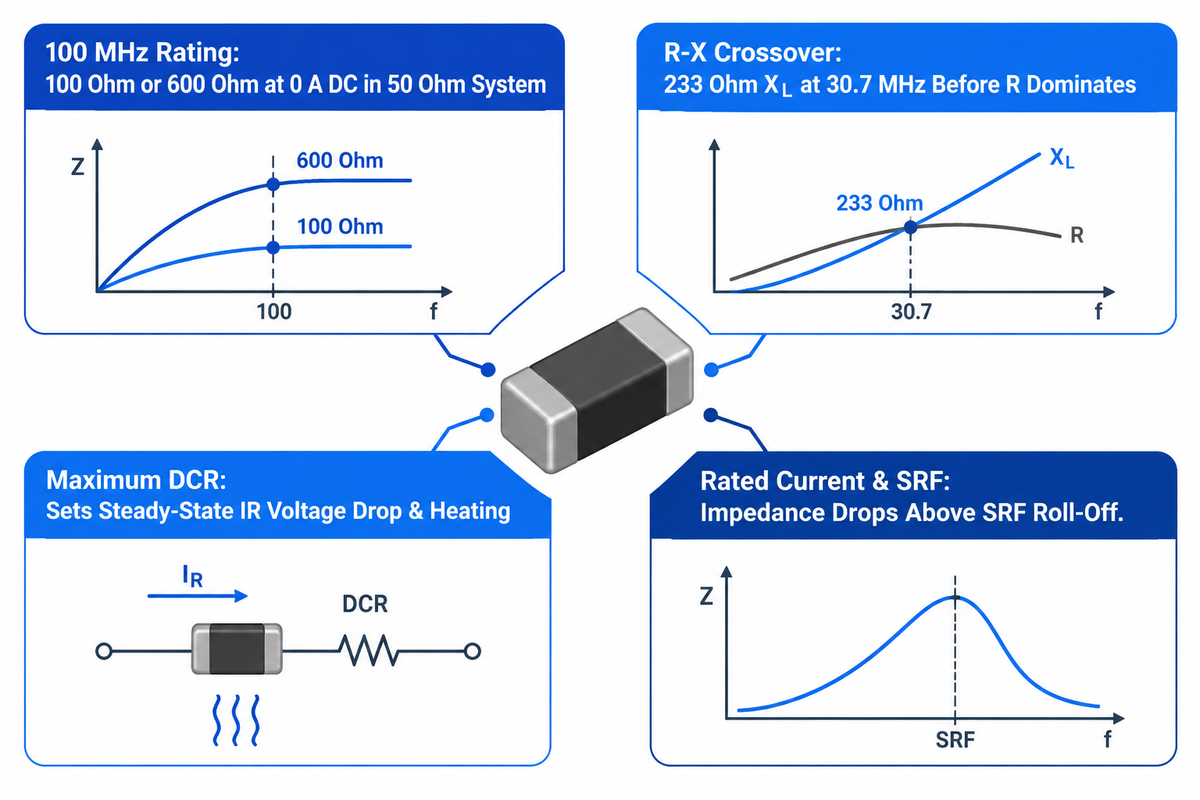
Four datasheet metrics dictate performance of an SMD ferrite bead under load: nominal impedance at 100 MHz, R-X-Z frequency response curves, maximum DC resistance (DCR) and rated current under DC bias. Analyzing all four parameters in unison prevents core saturation, excessive IR voltage drop and high-frequency capacitive bypass on production boards.
Reference Analog Devices Application Note AN-1368 (Ferrite Beads Demystified) for further explanation on nominal impedance. As explained in Analog Devices Application Note AN-1368 (Ferrite Beads Demystified), manufacturers commonly specify nominal impedance at 100 MHz and also provide impedance curves across frequency. Those standard curves are measured at zero DC bias current. Picking a part from that single 100 MHz number without checking DC bias curves is a main reason for filter failure. You should verify all four of the following parameters on the datasheet prior to locking the part number in your BOM.
- At 100 MHz (|Z|100MHz), the headline rating (100 Ω on TDK MPZ1608S101A or 600 Ω on consumer beads) is measured with 0 A DC bias in a 50 Ω system. For actual in circuit attenuation under load, vendor DC bias derating curves need to be consulted.
- For the R and X crossover frequency, the point is reached at which resistive loss R is greater than inductive reactance XL. On the Tyco BMB2A1000LN2 tested by Analog Devices, inductive reactance is 233 Ω at 30.7 MHz before resistive loss dominates around 100 MHz. A lower crossover frequency can improve damping when it provides substantial resistive impedance at the switching-ripple or filter-resonance frequency.
- For maximum DC resistance (DCR), steady-state resistance sets the IR voltage drop and ohmic heating along the power rail. High-impedance signal beads have higher DC resistance than low DCR power beads.
- For rated current (IR) and self-resonant frequency (SRF), a thermally rated ferrite bead defines rated current by its specified temperature-rise limit. An impedance-based rating limits the permitted change in impedance with DC bias. Above SRF (set by parasitic capacitance like the 1.678 pF CPAR on the BMB2A1000LN2), impedance decreases as the bead becomes capacitive.
SMD Package Sizes (0201 to 1206) and Internal Construction: Multilayer Chip vs. Wirewound Beads
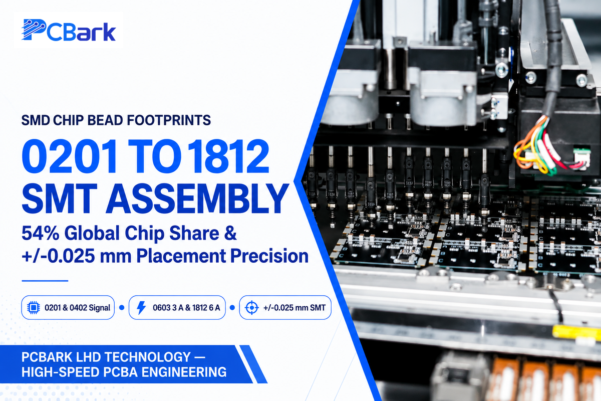
Multilayer SMD chip ferrite beads dominate modern PCBs, with footprints spanning compact 0201 and 0402 packages for signal lines up to 0603, 1206, and 1812 packages for multi-amp power rails. According to Industry Research’s 2026 global ferrite bead market report, chip ferrite beads accounted for 54% of the 12.4 billion units consumed in 2025.
According to the same Industry Research report, surface-mount installations grew by 31% in compact electronic devices during 2024. Inside a multilayer chip bead, conductive silver-palladium electrodes are co-fired between thin ceramic ferrite sheets to form a sealed magnetic path. Compact 0201 and 0402 SMD ferrite beads serve low-current signal and local IC supply lines, with nominal impedance options in the 100 Ω to 600 Ω class. Altium’s PCB ferrite bead selection guide discusses standard 0402 and 0603 passive footprints. Meanwhile, LHD Technology (PCBark) supports 0201 capability and ±0.025 mm SMT placement precision on our fine-pitch 0201 and BGA surface-mount assembly lines. By contrast, the TDK HF57BB3.5X3X1.3 cylindrical NiZn core measures 3.5 mm OD × 1.3 mm ID × 3 mm length. It was tested under magnetic fields up to ±500 mT at 25 °C in PMC12526085.
| EIA Package Code | Verified Benchmark Part (Analog Devices AN-1368) | Nominal 100 MHz Impedance (0 A Bias) | Rated DC Current (IR) | Impedance under DC Bias (Reported by AN-1368) |
|---|---|---|---|---|
| 0603 (1608 Metric) | TDK MPZ1608S101A multilayer power bead | 100 Ω at 100 MHz | 3 A rated DC current | Drops to 10 Ω at 1.5 A (at about 50% of rated current per data from AN-1368) |
| 1812 (4532 Metric) | Würth Elektronik 742 792 510 power bead | 70 Ω at 100 MHz | 6 A rated DC current | Drops to 15 Ω at 3.0 A (at about 50% of rated current per data from AN-1368) |
How to Choose and Calculate Ferrite Bead Values: Worked Example for a 3.3 V Supply Rail
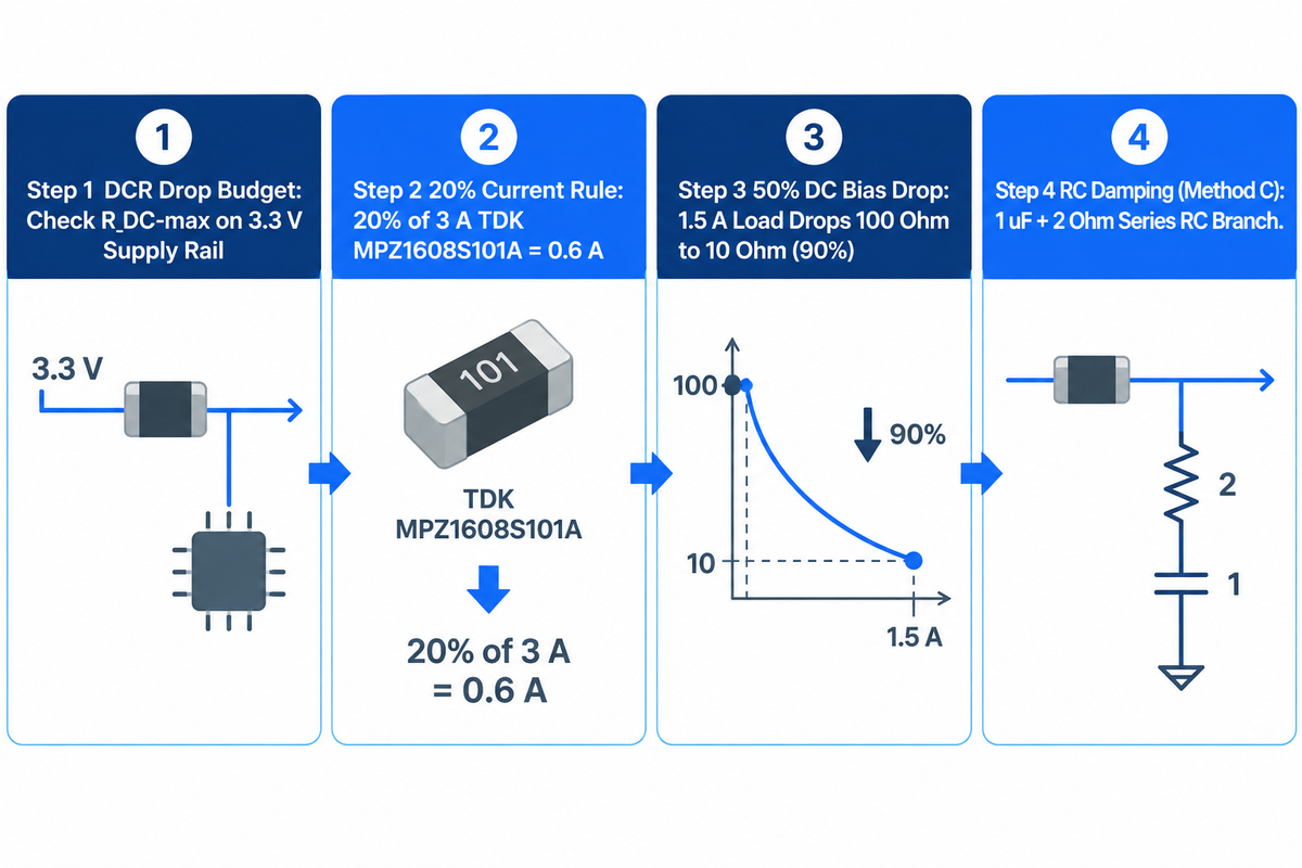
The 20%-of-Ir rule is a sizing convention employed by conservative engineers. The 20%-of-Ir rule is a conservative sizing guideline; effective noise suppression requires sufficient bead impedance at the operating DC current and noise frequency. Engineers also check maximum DC resistance against the rail’s voltage-drop budget and add RC damping to prevent low-frequency LC peaking.
DC current through the bead induces a magnetic bias that can reduce effective permeability and high-frequency impedance. Stronger bias can drive the ferrite toward saturation. Both Analog Devices AN-1368 and Altium’s saturation measurements report that at about 50% of rated current, inductance and impedance can drop by up to 90%. Likewise, EDN reports that a nominal 600 Ω bead can deliver only 50 Ω near its maximum rated DC current. As Murata’s EMIFIL engineering guide notes, legacy digital circuits used 5 V supplies. Modern digital boards run on 3.3 V, 1.8 V, and 1.3 V rails with tight voltage-drop budgets.
Worked Calculation: Calculation to Size 3.3 V Digital Clock Supply Rail Filter
- Step 1 – Check DC Resistance and rail voltage drop: For a 3.3 V digital supply rail, calculate the maximum permitted DC voltage drop (RDC-max) using the formula RDC-max = ΔVmax / Iload. The check ensures the bead’s DCR doesn’t violate IC supply tolerance.
- Step 2, Apply the 20% rated current guideline: According to Analog Devices AN-1368, a design guideline for power supply filtering is operating ferrite beads at about 20% of their rated DC current. For a 3 A rated TDK MPZ1608S101A (0603 package, 100 Ω at 100 MHz), about 20% of rated current equals 0.6 A.
- Step 3, Verify derated 100 MHz impedance under load: As reported by Analog Devices AN-1368, applying about 50% of rated current (1.5 A on the 3 A TDK MPZ1608S101A) causes 100 MHz impedance to drop by up to 90% from 100 Ω to 10 Ω. It is always required to read the vendor’s DC bias curve at the operating load current to confirm retained resistive impedance.
- Step 4, Check Source/Load Impedance and RC Damping: At 100 MHz, a low-impedance shunt capacitor and the series bead form a voltage divider that attenuates noise. The divider uses the bead’s impedance under operating DC bias, together with the source and shunt impedances. To damp low-frequency LC peaking without adding DC drop, AN-1368 Method C places a 1 μF capacitor in series with a 2 Ω resistor.
When Not to Use Ferrite Beads: DC Bias Saturation, PDN LC Ringing, and Ground-Plane Mistakes
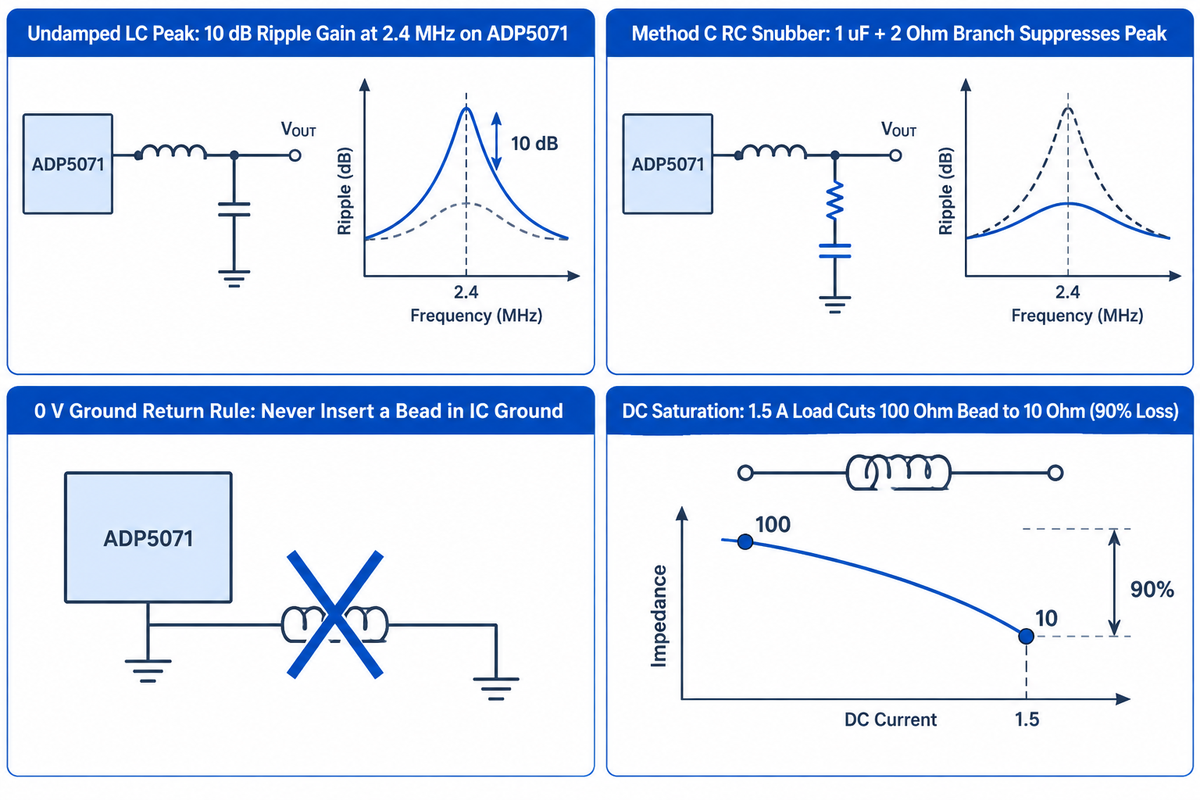
Don’t put an undamped ferrite bead in series with a low-ESR ceramic capacitor when the switching-ripple frequency falls within the bead’s inductive region. A ferrite bead on the 0 V ground return raises high-frequency return-path impedance and can cause resonant ground bounce.
In the Analog Devices AN-1368 example, the TDK MPZ1608S101A behaves predominantly as an inductor near the filter’s 2.5 MHz resonance, below its 20–30 MHz resistive crossover. A ferrite bead and ceramic capacitor can form an underdamped LC network when circuit losses are low, amplifying power rail ripple near the network’s resonant frequency. In AN-1368 lab tests on an ADP5071 regulator, this undamped network produced a 10 dB gain at the 2.4 MHz fundamental ripple frequency. EDN’s design pitfall analysis also notes this high-Q LC tank risk. Adding a parallel RC damping branch (such as a 1 μF capacitor in series with a 2 Ω resistor in AN-1368 Method C) suppresses that peak. On multilayer boards, pairing PDN damping with our 8-to-12-layer PCB stackup and power-plane impedance design rules keeps plane capacitance tightly coupled.
When not to use ferrite beads?
A ferrite bead on the 0 V ground return raises high-frequency return-path impedance and can cause resonant ground bounce. Standard power beads on multi gigabit differential pair conductors can also degrade signal integrity. On a power rail, inadequate impedance under DC bias, excessive temperature rise, or excessive voltage drop makes a bead unsuitable.
As EMC engineers note in EEVblog’s PCB ferrite bead design thread, inserting impedance in the 0 V return raises high-frequency return-path impedance and can cause resonant ground bounce. High DC bias can also substantially reduce a bead’s high-frequency impedance. In Analog Devices AN-1368, applying about 50% of rated current (1.5 A) reduces the TDK MPZ1608S101A’s 100 MHz impedance by 90% from 100 Ω to 10 Ω.
Where to Place Ferrite Beads on a PCB: Power Rail Pi-Filters, I/O Bulkheads, and SMT Pad Layout
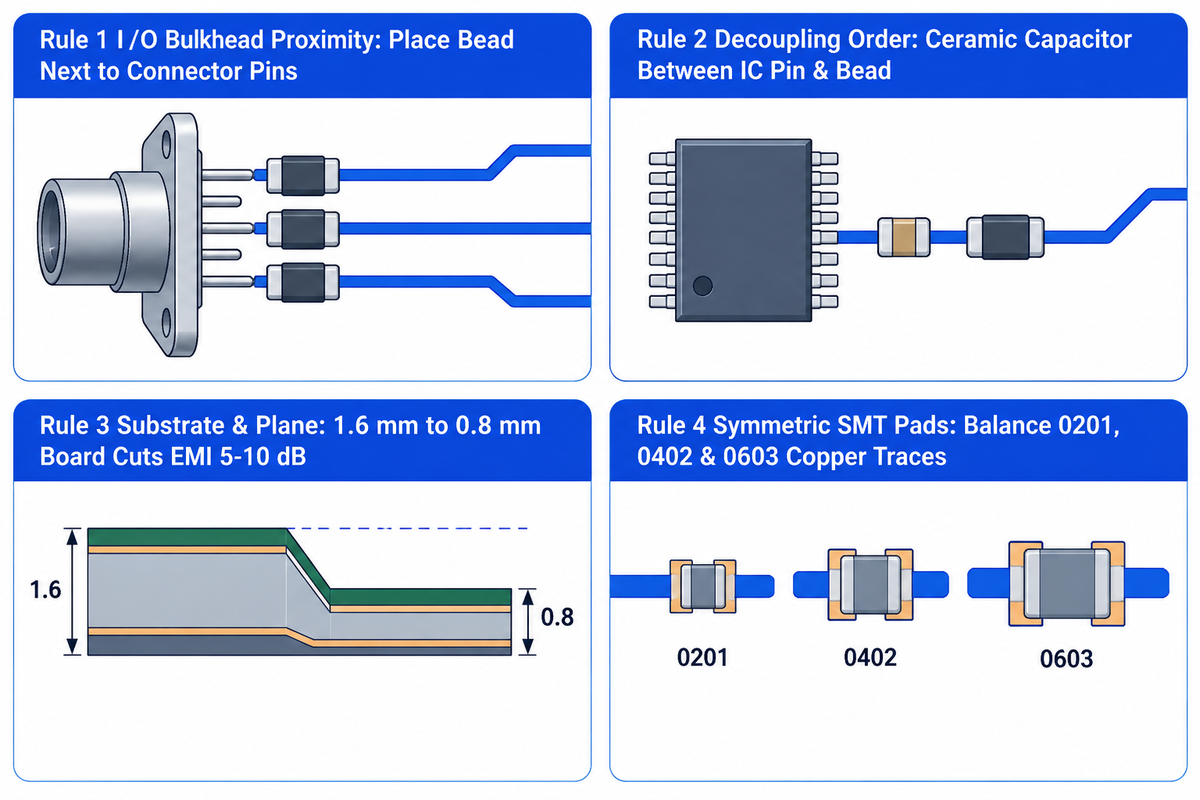
Place a PCB ferrite bead at the boundary of the noise (either next to an external I/O connector bulkhead or between the voltage regulator output and the local IC decoupling capacitor). Trace impedance and board thickness, along with component order, influence the filter’s high-frequency attenuation in a PCB layout.
As documented in Murata’s EMIFIL PCB layout experiments, engineers tested a 40 MHz clock line with a 10 cm trace length and 3.3 V supply on a 1.6 mm double-sided board. Matching trace characteristic impedance from 130 Ω (0.30 mm pattern width) to 50 Ω (3.1 mm pattern width) reduced radiated EMI. Reducing PCB thickness from 1.6 mm to 0.8 mm also lowered radiated noise by 5 dB to 10 dB.
Where do you put ferrite beads?
Place SMD ferrite beads in series with the positive power supply line between the regulator output and the local IC bypass capacitor, or at the entry pads of external I/O cables. Keeping the beads at the noise boundary allows high frequency switching currents to be confined to local planes.
- For connector bulkhead proximity, place I/O filter ferrite beads next to connector pins. This placement stops electromagnetic emissions from coupling onto internal traces.
- For decoupling capacitor order on an IC supply pin, place the high-frequency ceramic capacitor between the IC pin and the ferrite bead. This allows local switching transients to bypass directly to the IC return pin.
- For parasitic bypass prevention, keep unfiltered and filtered traces as far apart as possible. Never route a ferrite bead over a split reference plane.
- For symmetrical thermal balance of SMT pads, use balanced copper trace connections at both ends of 0201, 0402, and 0603 beads to help reduce tombstoning risk. Running a pre-production DFM land-pattern and pad thermal balance review will catch pad asymmetry.
Application Guide by Circuit Type: Switching Regulators, Analog/PLL Rails, and High-Speed USB/HDMI Lines
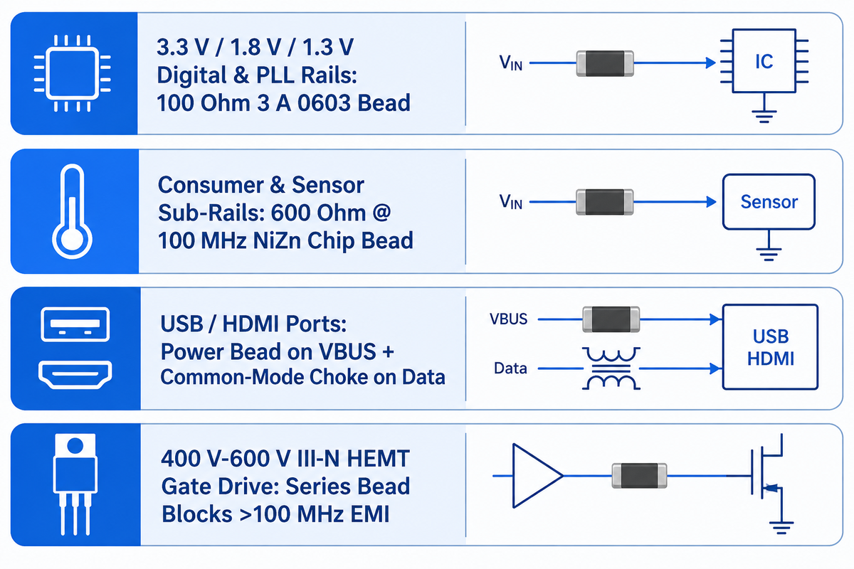
Separating high-current power rail filtering from sensitive analog/PLL isolation and high-speed differential interfaces is required when matching a ferrite bead to a circuit subsystem. As reported by Industry Research’s market deployment analysis, the industry trend in consumer electronic design has seen the use of higher average impedance ratings (typically around 600 Ω at 100 MHz) for digital power rails.
Engineers filter power supply rails on both the USB and HDMI interface using the same principle. A 600 Ω chip bead can attenuate VBUS noise when it retains sufficient resistive impedance at the noise frequencies under the operating DC load. It must also form an attenuating divider with the source and load impedances. By the same principle, placing high-capacitance power beads on high-speed multi-gigabit differential pairs degrades signal edges. A common mode choke can suppress common-mode noise on differential signals if its differential insertion and return losses are within the interface signal integrity budget. In high-voltage USPTO patent (US9660640B2), a ferrite bead is placed in series with the gate of a 400 V to 600 V III-N HEMT power transistor. It blocks EMI noise above 100 MHz.
| Circuit Subsystem | Primary EMI / RFI Challenge | Recommended Component & Benchmark Spec | Critical Design Boundary |
|---|---|---|---|
| 3.3 V / 1.8 V / 1.3 V Digital & PLL Supply Rails | 100 MHz clock harmonics coupling into shared power plane | Low-DCR SMD bead (100 Ω at 100 MHz, 3 A 0603 TDK MPZ1608S101A) | Verify impedance under DC bias (about 20% IR guideline per AN-1368) and add RC damping (1 μF + 2 Ω) |
| Consumer Electronics & Sensor Sub-Rails | Broadband radiated and conducted digital switching noise | NiZn chip bead with a resistive region covering the target noise frequencies | EDN describes a nominal 600 Ω bead whose impedance falls to about 50 Ω near its rated DC current |
| USB / HDMI Interface Ports | Supply-line conducted noise and differential-pair common-mode emissions | Power-line ferrite bead for supply filtering; interface-compatible common-mode choke for common-mode noise filtering | High-capacitance power beads can degrade multi-Gbps differential signals |
| 400 V–600 V III-N HEMT Power Switch Gate Drive | Parasitic gate-loop oscillation above 100 MHz during fast switching | Gate-series ferrite bead per US9660640B2 architecture | Suppresses >100 MHz EMI while preserving gate drive current flow |
Automotive AEC-Q200 Qualification, GHz Noise Suppression, and 2025–2026 Miniaturization Trends

Automotive electrification and compact multilayer boards are driving demand for high-reliability SMD chip beads that maintain resistive impedance above 100 MHz under thermal stress. As forecasted by the 2026 Industry Research report, ferrite beads will be seen in ~78% of the advanced PCBs used in Electric Vehicles, Laptops and Smartphones.
According to the same Industry Research study, the adoption of automotive-grade ferrite beads increased by 27% in high-voltage battery management systems (BMS). For the period of 2025–2026, two key engineering priorities affect automotive and GHz ferrite selection. First, for a given inductance, a smaller CPAR (such as the 1.678 pF CPAR of the model in Analog Devices AN-1368) would result in a higher self-resonant frequency. Suppression of GHz harmonics requires sufficient resistive impedance at those frequencies. Second, for automotive ECU and BMS boards, AEC-Q200 covers the qualification of passive components. Meanwhile, IPC Class 3 assembly acceptance applies when specified by the customer or product requirements, as discussed in our guide to automotive-grade PCB manufacturing . For more information on this, please see our article on automotive-grade PCB manufacturing.
Ferrite Bead Pricing, Top Manufacturers, and Turnkey PCBA Sourcing Checklist
Locking the exact manufacturer part number, 100 MHz impedance, DC resistance, and rated current in your bill of materials (BOM) prevents wrong-curve substitutions during turnkey PCB assembly. Per the Industry Research (Report 118586), the global ferrite bead market is expected to increase from USD 929.73 Million in 2026 to USD 1649.74 Million by 2035 at a CAGR of 6.58%.
According to Industry Research, global consumption exceeded 12.4 billion units in 2025. The top five manufacturers account for 57% of production, led by TDK at 24% and Murata at 19%, alongside Würth Elektronik, Taiyo Yuden, and Fair-Rite. Our technical and market sources don’t publish fixed reel or cut-tape unit prices for 0201, 0402, 0603, 1206, or 1812 packages or SMT placement fees. Exact component and assembly pricing requires a direct quote based on MPN, AEC-Q200 qualification grade, and order quantity.
Where can I purchase ferrite beads?
Engineers can purchase SMD and through-hole ferrite beads in full tape-and-reel or cut-tape quantities from authorized electronics distributors or through a turnkey PCB assembly supplier. When evaluating suppliers, engineers select TDK, Murata, Würth Elektronik, Taiyo Yuden and Fair-Rite, for documented R-X-Z and DC bias curves.
Our research sources don’t cite any specific distributor portals or rank third-party component sellers. For assembled boards through turnkey PCB assembly BOM verification and component sourcing, LHD Technology (PCBark) specifies 0201 capability and ±0.025 mm SMT placement tolerance, supported by pre-reflow DFM pad review and post-reflow AOI and X-ray solder joint verification.
The 4-Point PDN Damping & Layout Fit Check: Turnkey PCBA BOM & DFM Verification Checklist
| Verification Item | Engineering Requirement to Lock in BOM / Gerber Notes | Failure Prevented on Assembled Board |
|---|---|---|
| 1. Complete Manufacturer Part Number (MPN) | Specify exact MPN (TDK MPZ1608S101A or Würth 742 792 510) rather than generic “100R 0603 Ferrite” | Prevents substituting a high-DCR signal bead onto a 3.3 V power supply line |
| 2. DC Bias Derating Margin | Operating current satisfies both the required noise-frequency impedance under DC bias and the bead’s thermal limits | DC-bias impedance determines filtering performance; temperature rise limits current capacity |
| 3. PDN LC Resonance Damping | In the Analog Devices AN-1368 example, Method C adds a damping branch comprising a 1 μF capacitor in series with a 2 Ω resistor | Reduces the 2.4 MHz fundamental ripple by 15 dB relative to the undamped circuit |
| 4. Pad Symmetry & Stencil Aperture | Balance copper trace widths and thermal reliefs on both 0201, 0402, and 0603 terminals | Helps reduce tombstoning risk and open solder joints during SMT reflow |
Frequently Asked Questions About Ferrite Beads on PCBs
1. Can I replace a ferrite bead with a 0-ohm resistor during PCB prototyping?
Yes, placing a 0-ohm jumper resistor on the same SMD footprint during board bring-up is a common practice to check baseline DC voltage drop first. During compliance testing, if conducted or radiated EMI peaks appear, you can then swap in a specific filter ferrite bead. In early stage lab validations, this leads to less layout rework.
2. Why does my power rail oscillate after adding a ferrite bead and ceramic capacitor?
As mentioned in the example from Analog Devices AN-1368, the TDK MPZ1608S101A predominantly behaves as an inductor close to the filter’s 2.5 MHz resonance below its 20-30 MHz resistive crossover. When circuit losses are low, that inductive reactance and a low-ESR ceramic capacitor can form an underdamped LC network, which produced a 10 dB gain at 2.4 MHz in the cited example. Adding AN-1368 Method C RC damping (1 μF in series with 2 Ω) suppresses the peak.
3. Do SMD ferrite beads have polarity or orientation markings on the PCB?
Surface-mount chip ferrite beads are non-polarized passive electronic components that can be mounted in either direction during automated pick-and-place assembly. Internally, they have a ceramic ferromagnetic core and silver-palladium electrodes that behave symmetrically regardless of which side of the component is connected to the supply voltage, unlike polarized diodes or capacitors. Using symmetric solder mask openings and balanced copper connections on 0201, 0402, and 0603 pads helps reduce the risk of tombstoning.
4. What does 600 ohms at 100 MHz mean on a ferrite bead datasheet?
It means the component presents 600 ohms of total impedance magnitude to a 100 MHz test signal at zero DC bias.
5. How do you test a suspect ferrite bead on an assembled circuit board with a multimeter?
Set your digital multimeter to the ohms scale and measure across the terminals of the component. In the absence of board power, a good SMD ferrite bead should read a low DC resistance in line with the component’s specs. An open circuit may be caused by an open solder joint or poor contact. An open circuit doesn’t necessarily indicate overcurrent surge damage.
6. Can you put two ferrite beads in parallel to double the current rating?
Ferrite beads can operate in parallel, providing each branch is under its limit. The equal current sharing in the parallel combination isn’t guaranteed and can affect the performance of the circuit.
7. How does ambient board temperature affect ferrite bead current ratings?
Ambient temperatures affect allowable DC current through self-heating. When ambient temperature plus self-heating would exceed a bead’s specified operating-temperature limit, engineers follow the manufacturer’s temperature derating curve to reduce allowable current and keep the bead’s temperature within that rated limit.
References & Sources
- Analog Devices — AN-1368: Ferrite Beads Demystified (Analog Dialogue): Z-R-X impedance modeling of Tyco BMB2A1000LN2 (233 Ω at 30.7 MHz, 1.208 μH, 1.678 pF), 50% DC bias drop on TDK MPZ1608S101A and Würth 742 792 510, 20% rated current rule, and 10 dB LC gain at 2.4 MHz.
- Murata Manufacturing — EMIFIL Noise Suppression Know-How: Digital Circuit EMI & PCB Substrate Thickness: 100 MHz impedance index, 3.3 V / 1.8 V / 1.3 V digital rails, 50 Ω line matching (0.30 mm to 3.1 mm), and 5–10 dB radiation reduction from 1.6 mm to 0.8 mm PCB thickness.
- International Electrotechnical Commission (IEC)
IEC 62024-1:2024/COR1:2025 Edition 4.0
High frequency inductive components – Electrical characteristics and measuring methods.
- National Center for Biotechnology Information (PMC)
Peer-Reviewed Study on Commercial NiZn Ferrite Beads (PMC12526085, 2025)
Magnetic flux concentration and hysteresis loops up to ±500 mT on TDK HF57BB3.5X3X1.3 NiZn beads (1.5-2.0x pulse amplitude and 30-40% energy increase).
- EDN Network — The Secret Life of a Ferrite Bead: More Than Just a Lump on a Wire: 10–30 MHz reactance to 100 MHz resistance transition, NiZn 10³–10⁶ Ω·cm resistivity, 600 Ω to 50 Ω DC saturation drop, and high-Q LC tank pitfall.
- Altium Resources — How do Ferrite Beads Work and how do you choose the Right One? : SMD packaging with 0402/0603 footprint, and up to 90% impedance reduction with high current saturation.
- everything RF — What is a Ferrite Bead? : 100 MHz impedance rating and thermal dissipation of high frequency noise.
- EEVblog Electronics Community Forum — How to Use Ferrite Beads in PCB Design: Engineering field consensus against 0 V ground return ferrites and full-rated-current saturation.
- United States Patent and Trademark Office (USPTO) — US Patent US9660640B2: Switching Circuits Having Ferrite Beads: Gate-series ferrite bead EMI suppression above 100 MHz in 400 V–600 V III-N HEMT half-bridge power stages.
- Industry Research — Global Ferrite Bead Market Report (118586, 2026–2035): USD 929.73M to USD 1649.74M market forecast (6.58% CAGR), 12.4 billion annual units (54% chip beads), 78% advanced PCB integration, and 27% automotive BMS growth.
Editorial & Technical Review: Authored by GW and reviewed by the LHD Technology (PCBark) PCB & PCBA engineering team.
WHY WE WRITE THIS
About PCBark Engineering Insights
PCBark shares technical PCB fabrication and assembly guides based on real engineering review and manufacturing experience. We help teams compare materials, stackups, DFM risks, component sourcing, inspection plans, and production routes before they move from prototype to volume builds.
16+ yrs EMS experience
1-42 PCB layers
500,000 m2 annual PCB capacity
IPC Class 2/3 build discipline
DFM + test review