Get in touch with PCBark Company



A capacitor symbol identifies a component that stores electrical energy in an electric field. Two parallel plates usually indicate a fixed capacitor; a plus sign identifies a positive connection; an arrow identifies adjustment. Read the value and part number associated with the symbol to select a physical component.
The symbol for a capacitor describes how a component connects within a circuit. It doesn’t specify its dielectric, package size or rated voltage by itself. This reference guide to capacitor symbols connects the drawings to the markings and assembly information needed to select and place the part.
Updated: November 2026
Capacitor Symbol Chart: Identify the Main Types
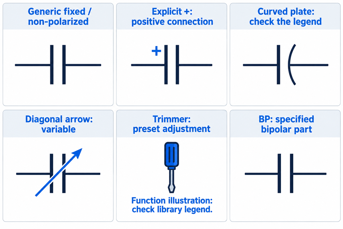
The basic capacitor symbol consists of two parallel lines separated by a gap, with a connection to each plate. Other markings distinguish common capacitor symbols: a plus sign identifies polarity while a diagonal arrow identifies adjustable capacitance. The gap represents electrical separation of the electrodes, not a missing wire.
NASA’s crystal-radio lesson describes the parallel-plate drawing and a slanted arrow for a variable capacitor.
| Drawing or label | Read it as | Check before selecting a part |
|---|---|---|
| Two straight plates, no polarity mark | Generic fixed capacitor or non-polarized symbol | Dielectric and rating in the part specification |
| Explicit + at a connection | Polarized symbol; + identifies the positive side | Package marking and terminal assignment |
| One straight and one curved line | A convention requiring its legend or library definition | Explicit polarity labels; curve alone is insufficient |
| Diagonal arrow through the plates | Generic variable capacitor | Adjustment range and mechanism |
| Preset adjustment mark or trimmer label | Trimmer capacitor for calibration | Library legend and tool-access direction |
| BP or non-polar part description | A specified bipolar/non-polar capacitor | Exact series; an electrolytic construction need not imply polarization |
Ceramic capacitors and film capacitors can share the same non-polarized capacitor drawing. Disc ceramic capacitors and multilayer ceramic capacitors differ physically, but their ordinary schematic symbol need not differ. These types of capacitors are widely used in electronic circuits.
The University of Oklahoma’s capacitor notes explain how dielectric choice affects leakage, size and high-frequency behavior. These properties influence the design choice, even if the symbol stays the same. Symbols are used independently of package outline: changing a through-hole part to a surface-mount package requires a footprint change, even if the schematic stays the same. In timing circuits, the specified capacitance and its tolerance must survive the trip from the design to the purchase.
Which Capacitor Symbol Should I Use?
Use a symbol that represents the part’s polarity and adjustment function. For a fixed, non-polarized part, use a two-plate library symbol. If the capacitor is polarized, then use an appropriate polarized symbol and check the pin numbers. Choose a variable or preset-adjustment symbol for an adjustable part.
Add the exact manufacturer part number and footprint. Although aluminum electrolytic capacitors and molded tantalum parts may both require polarized symbols, their package markings differ. Reusing a symbol doesn’t validate a substitution. When understanding capacitor symbols in electronics design, trace the symbol pin through its numbered pad to the terminal of the selected part.
Polarized Capacitor Symbols: Find Positive and Negative
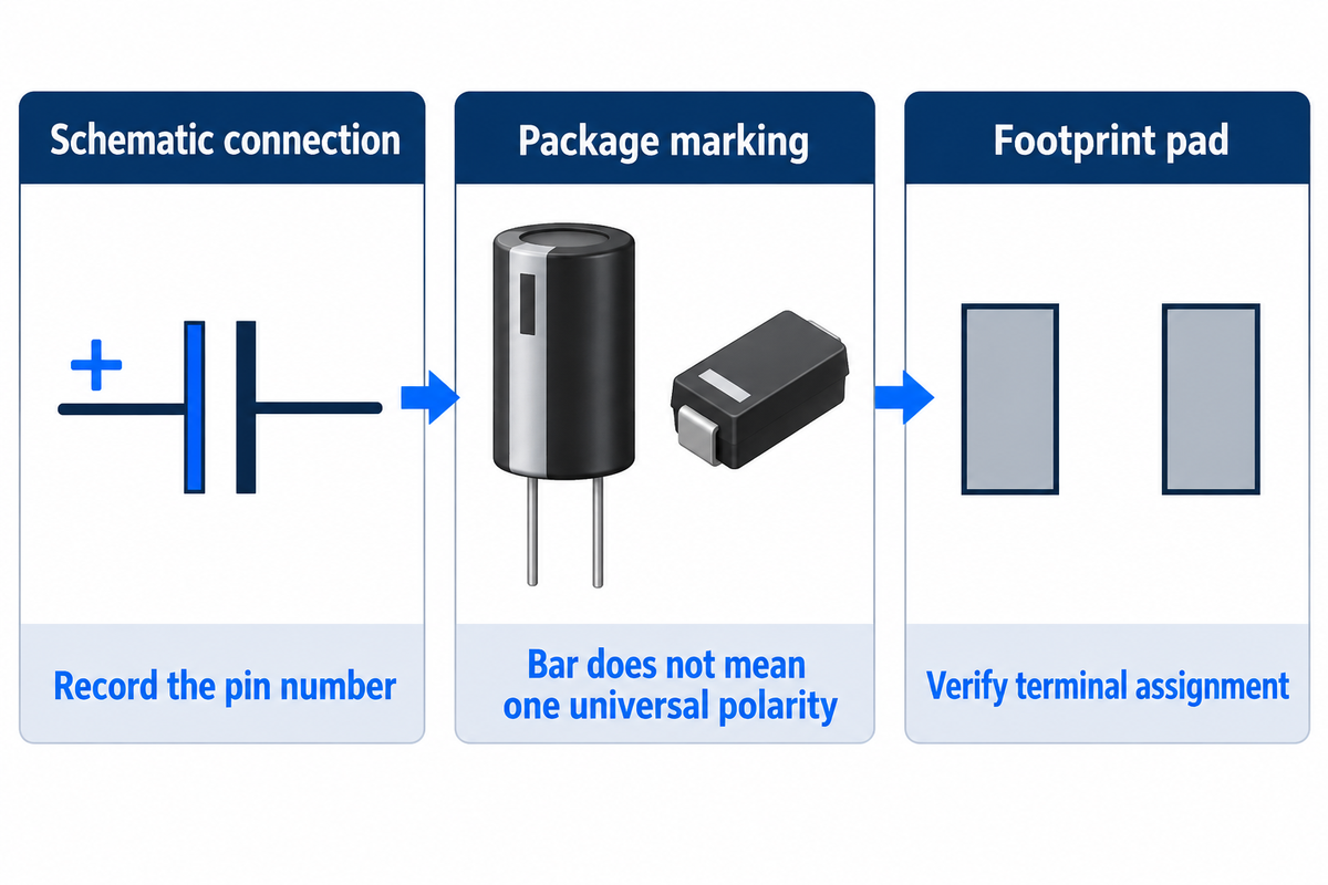
Read an explicit plus sign as the positive terminal, and verify that connection against the package drawing. For polarized electrolytic parts, don’t transfer a stripe rule between families. Vishay identifies the bar on its surface-mount tantalum capacitors as the positive anode. Another package may mark the negative terminal.
The Vishay tantalum FAQ also addresses orange conformal-coated devices lacking a body polarity marking, in which case the anode is identified by a wire nib. The Nichicon UD package drawing indicates the negative side of its aluminum-electrolytic package. Match each marking to the correct drawing. The Oklahoma notes state that reversing a polarized capacitor can damage it.
3-View Capacitor Polarity Crosswalk
Match the schematic connection, the manufacturer’s terminal identification, and the footprint pad prior to approving orientation.
Plus symbols represent the positive terminals in an explicitly marked polarized drawing. Record the pin beside each plus. Then compare the package.
| What you see | What it establishes | Next action |
|---|---|---|
| + beside a schematic terminal | Intended positive connection | Record that terminal’s pin number |
| A curved plate | A drawing feature, not a universal polarity rule | Read the symbol definition |
| White bar on Vishay surface-mount tantalum | Positive anode in the cited manufacturer convention | Match the bar end to the positive connection |
| Negative-side mark in the Nichicon UD drawing | Negative terminal for that package | Match it to the negative connection, not the tantalum positive-bar rule |
| No visible polarity markings | Insufficient information alone | Read the part number and package instructions |
| Square footprint pad | A pad shape chosen by the library designer | Read its number; do not assume positive |
| Shaded silkscreen area | An assembly graphic | Compare it with the approved package orientation |
| Symbol pin 1 and footprint pad 1 | Numbered mapping in KiCad | Verify which manufacturer terminal pad 1 represents |
| Replacement with a different marking style | A fresh orientation check is needed | Update the part record and inspection image together |
Consider a worked example of an assembly review of C7, a polarized bypass component. Procurement suggests the same nominal capacitance in a different package. The inspector sees the bar and wants to align it to the shaded end of the old outline. Stop at the mismatch. The old outline hasn’t defined what that bar means. Identify the replacement’s positive and negative terminals, trace the positive symbol pin to its numbered pad, then orient the package drawing to those pads. Design approves the mapping, procurement records the exact substitute and inspection uses its marking image. Matching only the value would leave the orientation question unanswered.
What Should I Do If a Capacitor Has No Polarity Markings?
Find its part number and manufacturer’s package drawing. A documented non-polarized type can be connected either way for polarity purposes; an unmarked polarized type still has a required orientation. If identification is missing, do not guess from body color, lead position or an old board’s shading.
For a loose replacement part, compare its package and dimensions with the intended bill of materials entry. If that comparison doesn’t establish identity, obtain an identified replacement. For anyone involved in electronics repair, record the unmarked component’s reference designator before removing it.
IEC vs ANSI Capacitor Symbols: Overlap and Exceptions
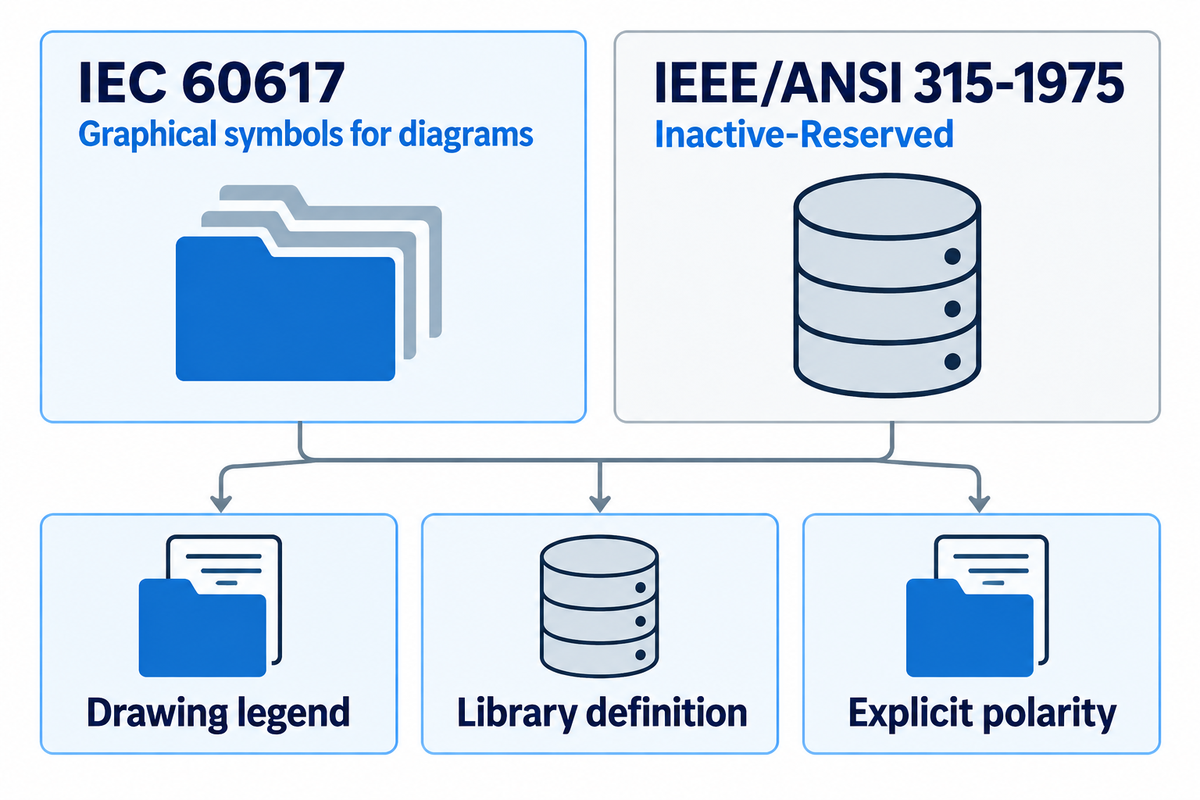
Read capacitor symbol standards using the drawing’s stated convention and explicit labels. A straight-versus-curved shortcut cannot reliably identify every IEC or ANSI drawing. When reading circuit diagrams of a legacy design, check the document’s legend, symbol-library definition and polarity before interpreting an icon to mean a package orientation.
The IEC 60617 database is a source of graphical symbols for diagrams. The IEEE catalog entry for IEEE/ANSI 315-1975 lists it as Inactive-Reserved. Preserve the legend for capacitor symbols used in older drawings when exchanging files with a supplier.
A plus sign next to the positive connection serves as a label representing the positive terminal when the drawing convention calls for explicit identification. A line representing the negative terminal must be interpreted within that same convention. The purpose of capacitor symbols is to indicate an electrical connection. Thus, a supplier should not need to infer polarity based on the country where the drawing originated.
The marking of non-polar parts with outside foil marks is an old issue. One account in Nuts & Volts discusses a body stripe identifying the lead connected to outside foil. That is a package-construction detail, not a rule that every curved schematic plate represents outside foil or proof of a positive or negative DC terminal.
Variable and Trimmer Capacitor Symbols
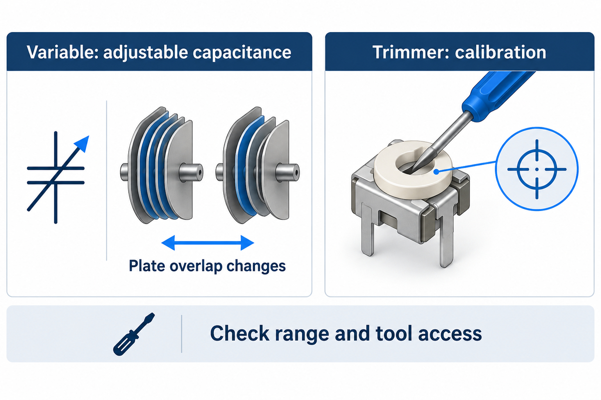
A variable capacitor allows adjustment of capacitance in a circuit; a trimmer is intended for calibration or preset adjustment. A diagonal arrow, or the library’s notation for preset adjustment, should be looked for, and the value range read. Variable capacitor symbols describe adjustability without specifying the mechanism, access direction or usable range of the physical component.
In NASA’s mechanical tuning example, rotating the shaft changes the overlap of the plates, which changes the capacitance of the capacitor. The symbol represents the adjustable electrical function, while the package determines how one makes the adjustment.
A small trimmer capacitor may calibrate a circuit during manufacture or troubleshooting, as described in this capacitor-symbol reference. Not every diagonal mark should be viewed as the same type of variable capacitor. Look to see if the library label states it as general adjustment or preset adjustment.
For tuning circuits, indicate the adjustment range of the component and leave physical access for the selected package. For a board-level layout situation, consider the RF and microwave PCB design guide.
Capacitor Values: C1, µF, nF and pF
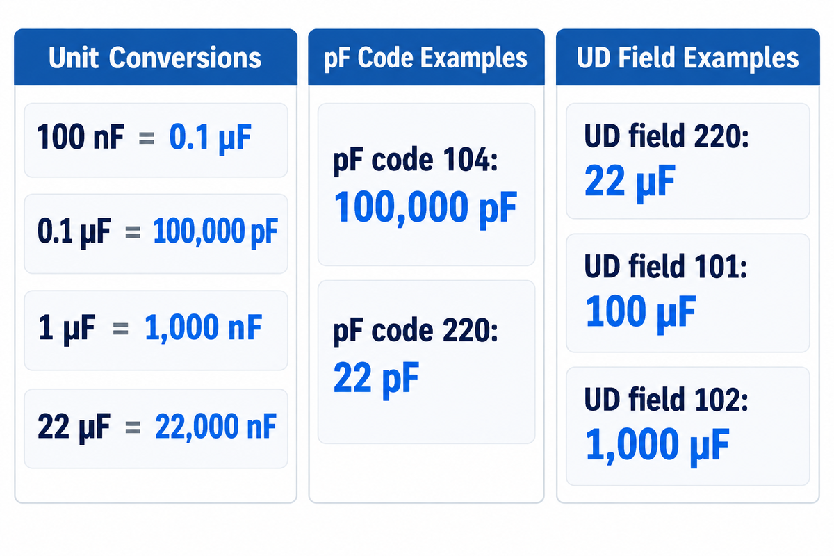
C1 is the reference designator identifying that capacitor, and the adjacent capacitance value specifies its nominal electrical value. The component’s voltage rating and tolerance are different specs used in circuit design and purchasing. The same standard capacitor drawing can accompany a small picofarad value or a much larger microfarad value without changing its basic shape.
According to NIST’s SI guide, one farad is 1 coulomb/volt. The micro, nano and pico prefixes are defined. The resulting conversions are exact: 1 µF = 1,000 nF = 1,000,000 pF. This equality doesn’t remove the component tolerance during manufacture.
| Input | Calculation or definition | Result |
|---|---|---|
| 100 nF | 100 ÷ 1,000 | 0.1 µF |
| 0.1 µF | 0.1 × 1,000,000 | 100,000 pF |
| 104, under a pF-based three-digit convention | 10 × 10,000 pF | 100,000 pF = 100 nF |
| Nichicon UD field 220 | Manufacturer’s 16 V, 22 µF part-number example | 22 µF, not 22 pF |
| 1 µF | 1 × 1,000 | 1,000 nF |
| 22 µF | 22 × 1,000 | 22,000 nF |
| 220, under the pF-based convention | 22 × 1 pF | 22 pF |
| Nichicon UD field 101 | Series capacitance table | 100 µF |
| Nichicon UD field 102 | Series capacitance table | 1,000 µF |
In the Vishay 293D datasheet, pF-based significant digits and a multiplier specify a value in ordering information. Body markings vary by case size. The Nichicon UD datasheet shows an example of a 22 µF part number with the field 220. Look for a coding system before performing any math.
In this worked example, a bill of materials calls for 100 nF, while a candidate part is described as 0.1 µF. Divide 100 by 1,000. The nominal capacitance values match. If a confirmed pF-based code reads 104, calculate 10 × 10,000 pF, then divide by 1,000 to obtain 100 nF. The procurement team can now evaluate the remaining fields: rated voltage, tolerance, dielectric and package. This calculation validates only the candidate part’s value equivalence. This calculation shouldn’t be applied to UD field 220 as the units defined by the manufacturer differ. When calculating value equivalence, document the original value and its unit or code alongside the calculated value in the purchasing record.
Where Should the Voltage Rating Be Displayed on the Schematic?
Place the required voltage rating in a visible component field near the capacitance when it needs to guide selection or review. Carry this requirement through the bill of materials (BOM) and exact part number. A value printed next to the symbol is helpful only if the released purchasing data agrees with it.
In this worked example, the label reads “C1, 22 µF, 16 V”: C1 is the reference, 22 µF is the nominal capacitance and 16 V is the specified rating. It isn’t a statement that every circuit node operates at 16 V. Choose the component for its actual electrical conditions and manufacturer limits; a single schematic icon supplies no universal derating percentage.
Capacitor Symbol on a Multimeter
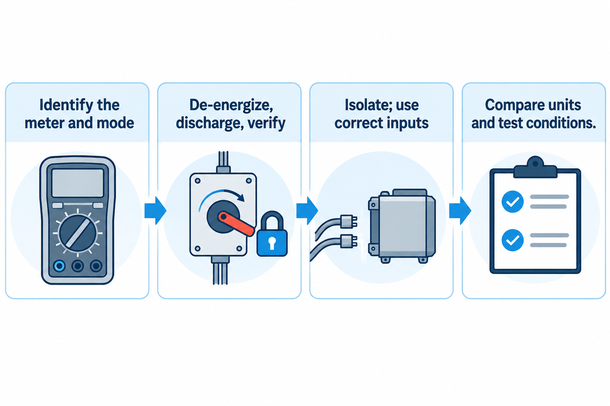
Find the two-electrode capacitor icon or an F, nF, or µF capacitance legend on the meter. It may share a switch position with another function. On the Fluke 287/289, the manual states users should select Menu, then the “Diode,Cap” menu item, and finally the Cap softkey when capacitance isn’t already selected.
Fluke’s capacitance-measurement guide calls for power off, discharge verification and detaching the capacitor from the circuit. Don’t assume a fixed waiting time makes a charged part ready to handle.
- Identify the meter model and capacitance mode in its manual.
- De-energize the equipment and complete its specified discharge and verification procedure.
- Isolate the component as indicated, and use the correct meter inputs and functions.
- Read the displayed unit, compare the result with the part specification and test conditions.
An OL reading isn’t a complete diagnosis. Fluke states that it can mean that the capacitance exceeds the selected range or that the component is faulty. Likewise, a plausible capacitance reading doesn’t test all failure modes. The Oklahoma teaching notes discuss leakage as a different property; a short circuit and too much leakage can’t be reduced to a single nominal value comparison.
For example, Nichicon specifies UD capacitance tolerance of ±20% at 120 Hz and 20°C. For its nominal 22 µF example, that tolerance spans 17.6–26.4 µF under the stated conditions. A handheld reading taken under different conditions is not automatically the same acceptance test.
From Schematic Symbol to PCB Footprint
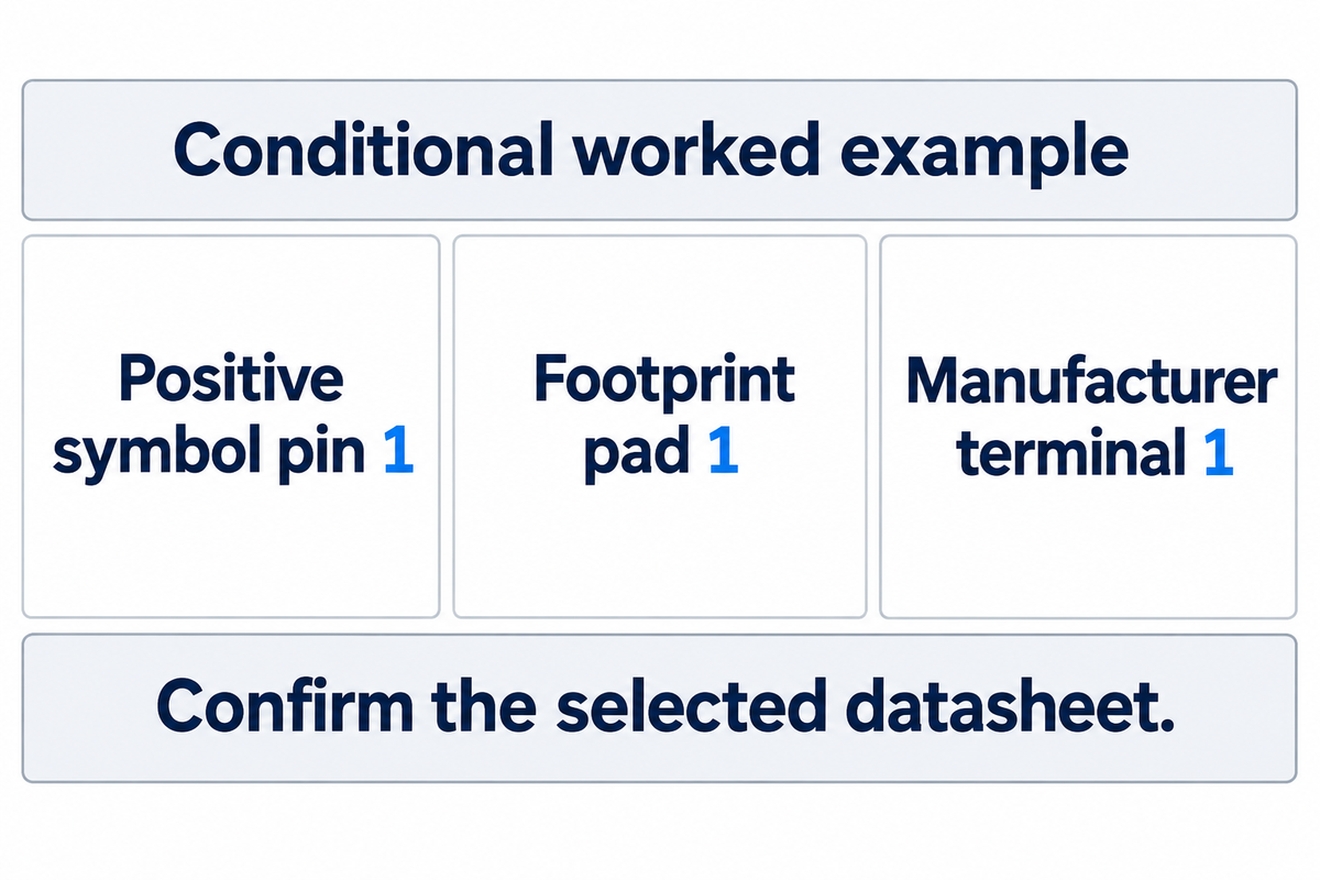
Verify that the selected component’s terminal numbering matches the symbol pins and footprint pads. Check orientation and package view prior to releasing assembly files.
“Symbol pins are the parts of a symbol that connect to wires in the schematic.”
MIT’s KiCad lab connects that mapping to the datasheet and asks for the exact part number. Library symbols provide pin numbers that must match the footprint pads; these electronic symbols convey circuit connections. Pin 1 is therefore a mapping identifier, not a universal word for positive. The same check applies when replacing a library symbol or assigning a new footprint.
In this second worked example, the datasheet for the selected two-terminal capacitor defines terminal 1 as the positive terminal. The designer assigns the positive symbol pin the number 1 and checks that footprint pad 1 occupies the corresponding package location. The reviewer then follows the board net to that pad and compares the assembly orientation with the datasheet view. If a different datasheet defines terminal numbering differently, reusing the previous mapping isn’t adequate. Update the mapping before the release. “Positive Symbol Pin 1 → Pad 1 → Manufacturer’s terminal 1” is recorded only after confirming the mapping for the selected part; it doesn’t apply to all capacitor circuit symbols.
For global capacitor sourcing, keep the manufacturer part number, quantity and approved alternatives the same for quotes. Different capacitor types with the same nominal value may require different footprints and inspection instructions. For PCBark’s design-for-manufacturing review, the published component-placement checks include polarity and footprint fit and call for bill of materials and centroid data.
Capacitor Checks Before You Send Assembly Files
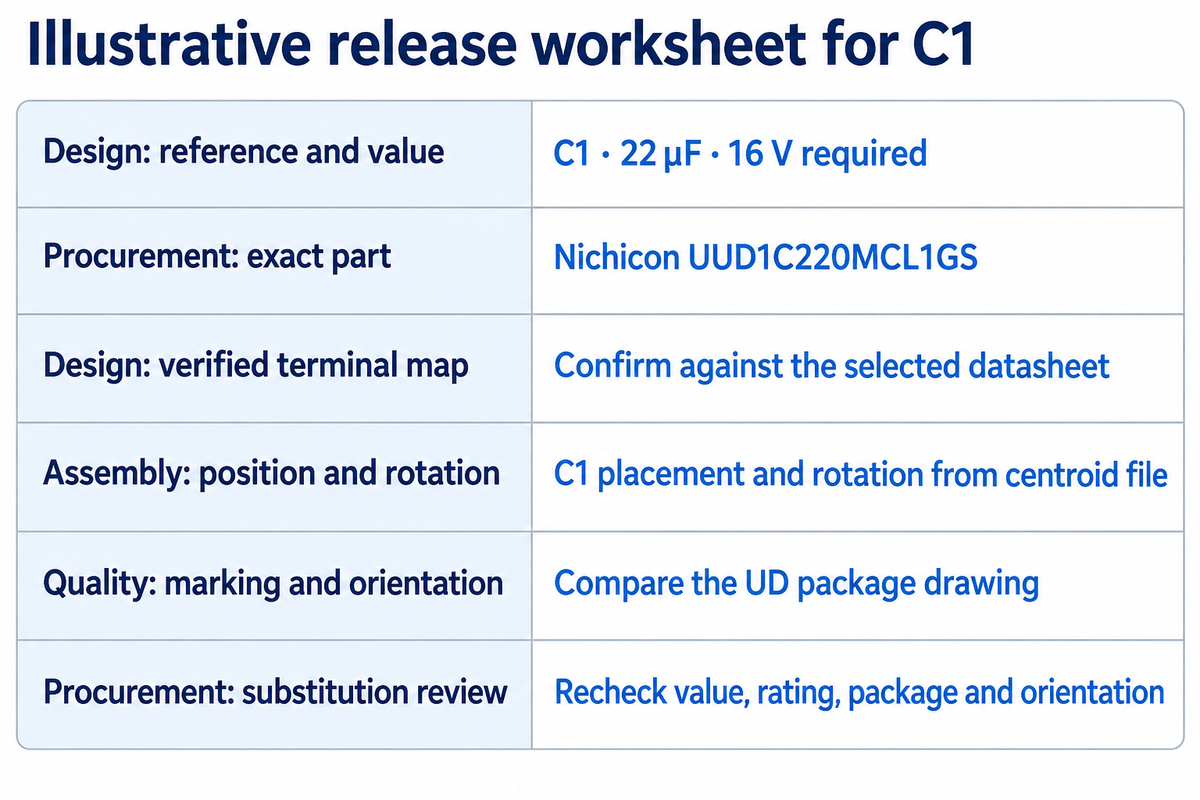
Release an exact part identity, a verified pin-to-pad map, and a clear orientation record. Procurement needs the component and approved alternatives; assembly needs position and rotation; inspection needs the correct marking convention. If those records disagree, resolve the affected reference designator before treating the file set as ready.
Refer to the MIT component-selection workflow to define the exact part and match the symbol and package. This worksheet uses Nichicon’s documented UUD1C220MCL1GS type-number example for the part fields and identifies the accompanying board-specific records. A completed worksheet should contain the exact part and its datasheet reference.
| Owner / field | Example entry | Release check |
|---|---|---|
| Design / reference and value | C1; 22 µF; 16 V required | Schematic and bill of materials agree |
| Procurement / identity | Nichicon UUD1C220MCL1GS | Use the exact suffix in the approved bill of materials |
| Design / terminal map | Example: positive pin 1 → pad 1 | Confirm against the selected datasheet |
| Assembly / position | C1 placement and rotation from centroid file | Match package view to board orientation |
| Quality / marking | Positive and negative sides in the UD package drawing | Assembly orientation agrees with the approved terminal map |
| Procurement / substitution | No substitute approved in this example | Recheck value, rating, package and orientation before approval |
During board inspection, compare against that approved record rather than a generic capacitor image.
Send the PCB files, BOM and placement data to PCBark for an assembly-file review, and identify uncertain capacitor substitutions by reference designator so the review team can check the affected part and orientation.
Frequently Asked Questions
What does a capacitor do?
A capacitor stores electrical energy in an electric field. Its capacitance relates stored electrical charge to the voltage across it. Designers use that behavior for functions such as filtering, timing and coupling.
The two electrodes are separated by a dielectric. The capacitor symbol represents that electrical function without showing the complete internal construction. In a power supply, the selected component’s value and operating limits still matter even when the drawing uses a familiar two-plate icon. Choose the actual part from the electrical requirements and its datasheet, not from the icon alone.
What is this symbol μf?
µF means microfarad, a unit of capacitance equal to one millionth of a farad. The proper SI unit symbol uses an uppercase F; µ is the micro prefix.
A value of 1 µF equals 1,000 nF, and 0.1 µF equals 100 nF. These are exact unit conversions from the SI prefixes listed by NIST. When copying a value into a bill of materials, keep the unit attached so that 100 nF doesn’t become an ambiguous “100.”
How do I tell if a capacitor is bad?
Check for visible damage and test the isolated component using the equipment and meter instructions. Compare measured results with the component’s specified limits. A capacitance reading alone can’t establish that every operating property is acceptable.
Before testing, de-energize the equipment, follow its discharge procedure and verify the remaining voltage. Fluke’s measurement guide distinguishes an overrange OL indication from a possible component fault, so OL isn’t a verdict by itself. If the meter range is suitable, investigate the part using the tests appropriate to its application; leakage and other operating behavior may require additional equipment.
Can a non-polarized capacitor replace a polarized capacitor?
Yes, provided capacitance, rated voltage, tolerance, relevant operating characteristics and physical fit match, and the circuit designer approves the exact substitute.
Different construction can change leakage, size and high-frequency behavior, as the Oklahoma capacitor notes explain. Multi-layer ceramic capacitors require the same part-specific comparison when proposed as alternatives. A part that fits the same symbol may still require a different footprint.
What is the capacitance of a “104” capacitor?
Under the common pF-based three-digit convention, 104 means 10 × 10,000 pF: 100,000 pF, 100 nF or 0.1 µF. Confirm that the manufacturer uses this coding convention.
Don’t apply it automatically to every three-digit field in a part number. Nichicon UD’s 220 example represents 22 µF in that series’ numbering system.
Related Reading
- 4-layer PCB stackup and layout guide
- 6-layer PCB design guide
- Rogers PCB materials guide
- PCB manufacturing process guide