Get in touch with PCBark Company

PCB Manufacturer for Industries · Robotics
Robotics PCB Manufacturing & Assembly for Reliable Robots
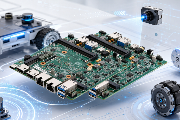
Robotics PCBs withstand what consumer boards never endure – relentless vibration, joint heat, and decade-long cycles of work. PCBark engineers them all under one turnkey process: rigid, HDI, flex, and rigid-flex PCBs; SMT; traceable component sourcing, all with IATF16949 and IPC-A-610 Class 2/3 control.
Robotics PCB · Field Reliability
Why Robotics PCBs Fail in the Field, and How to Build Them Right
Definition
What a robotics PCB is
it’s a printed circuit board for movement, heat, and duty-cycle resistance – designed for what’s in your robot.
What your robots use it for
controlling the onboard microcontroller, sensors, power distribution, and motor drivers as the control system that enables sensing, deciding, and moving.
Failure Mode
The failure rarely show up on the bench.
Inadequate reflow profiling leaves hidden micro-cracks under an AI processor that only surface after months of field thermal cycling.
Motor and actuator vibration then fatigues solder joints and vias until a board that “passed” quietly dies in service.
Process
That bench-top versus field-duty disconnect is rooted in how a board is manufactured – not how it’s drawn.
We bridge that gap using industrial assembly and SAC305 solder, an on-spec assembly process, and zero skipped inspection on production runs for a PCB that lives as long as your robot’s components, under an ISO 9001 quality system. We don’t just assemble robots; we engineer robotics PCBs to survive what yours can’t.
Robotics PCB Types & Capabilities, Rigid, HDI, Flex & Rigid-Flex
A robot isn’t built from one size of board. PCBs for robotics aren’t one product, a single robotics circuit board family spans rigid, HDI, flex, rigid-flex and metal-core construction, each chosen for a subsystem and its stress profile. For a humanoid or an industrial robot PCB program, PCBark designs that whole array into one coordinated process.
Rigid & Multilayer
Main control and power distribution boards. 4–16 layers, fine-pitch BGA, high-current copper.
Tg 130–155°C FR4 · buck converters · MOSFET arraysHDI
High-density interconnect for AI processors and dense sensor fusion. Laser microvias, via-in-pad, ELIC stackups.
2 mil trace/space · any-layer viasFlex & FPC
Sensor, vision and joint wiring that bends with the robot. Rolled-annealed copper for fatigue life.
Polyimide to 260°C · up to 200,000 bend cyclesRigid-Flex
One assembly that replaces board-to-board connectors in moving limbs, fewer failure points, less weight.
IPC-6013 · dynamic + static bend zonesMetal-Core (MCPCB)
Motor-driver and high-power boards that dump heat. Aluminum core moves heat where FR4 can’t.
1–8 W/m·K dielectric · core >200 W/m·KHigh-Frequency
Radar, LiDAR and high-speed comms. Low-Dk/Df laminates protect signal integrity.
Dk 2.2–10.2 · Rogers / LCPEach board type is a capability in its own right, our HDI PCB fabrication and turnkey PCB assembly lines feed the same robotics programs. To turn that into a buying decision, we map every board type to the subsystem it serves and the spec that governs the choice, what we call the Robotics PCB Type Selection Matrix.
| Robot subsystem | Recommended PCB type | Governing spec | Why |
|---|---|---|---|
| Main control / AI compute | Rigid multilayer / HDI | 2 mil trace, any-layer via | Fine-pitch BGA + DDR routing density |
| Sensor & vision (IMU, LiDAR, camera) | Flex / FPC | ≥200k bend cycles | Integrates into compact, moving structures |
| Motor & motion control (joints) | Rigid-flex + MCPCB | Dielectric 1–8 W/m·K | Heat dissipation + vibration survival at the joint |
| Power distribution | Rigid, heavy copper | 2–3 oz Cu, high-current | 12–24 V rails, low voltage drop |
| Communication (Wi-Fi/CAN/EtherCAT) | Flex / rigid-flex HF | Controlled impedance | Signal integrity over moving links |
Engineering Note, More Layers Is Not Always Better
A robotics rigid-flex PCB with many layers doesn’t necessarily make it more useful, and in many circumstances – as seen in its many complex processes – we want our robotic assemblies to reduce their reliance on a high number of flex components; keep dynamic-flex layers at two conductor layers to avoid adding thickness and rigidity. Certain patent-pending dynamic-flex structures (see USPTO 20240147626) even embed actuation and sensing into the flex itself.
Static (install-and-forget) bends are different, a rigid or rigid-flex board there can safely run 10 to 20 layers. And for high-volume, cost-sensitive builds, a plain rigid PCB plus a cable assembly can in fact be significantly less expensive than rigid-flex.
Specifications
Robotics-Grade PCB vs Standard PCB, The Reliability Gap
Two different PCBs with the same layout will often have wildly different lifetimes when installed inside an industrial robot or automated system-despite being functionally the same. the difference lies within the process of building them, from standard specifications of fabric to how solder is integrated into its components.
| Factor | Standard PCB | Robotics-grade PCB (PCBark) |
|---|---|---|
| Build standard | IPC-A-610 Class 1–2 | IPC-A-610 Class 2/3 + IPC-6012 |
| Inspection | Sample AOI | 100% AOI + X-Ray on BGA (Class 3) |
| Solder alloy | Standard SAC | SAC305 high-ductility near motors |
| Vibration handling | Not qualified | Underfill / staking + via stitching |
| Environmental protection | None | Conformal coating per IPC-CC-830 |
| Traceability | None | Lot-code traceable, AS5553-aligned sourcing |
We combine all this into a single named program – the Robotics-Grade Reliability Stack – allowing a buyer to simply check “robotics-grade” on every RFQ, rather than repeating all six standards. It adds Class 3 assembly and HALT/HASS style stress screening to any robotics design using conformal coating and thermal via heat paths on request, all under an ISO 9001-documented quality system.
“We treat every joint-mounted motor board as Class 3 by default. Vibration doesn’t care that a board passed at room temperature, so we stress-screen and X-ray the BGAs before a robotics board ever leaves the line.”
Engineering Your Robot’s Electronics, DFM, Signal Integrity & Thermal
Failure analysis on the majority of robotics boards we encounter goes back to flaws identified during a preliminary review: clearance between components, PCB trace width sufficient for the current supplied to the motors, or a thermal path that wasn’t even documented in theory. Our preventative design-for-manufacturing review process examines your PCB layout before its fabrication, avoiding costly failures on entire batches.
SPEC 01
High power integrity achieved through wide copper ground and power planes, optimally placed decoupling capacitors, and a full PDN review to ensure smooth power rail response under the heaviest of motor draws.
SPEC 02
High signal integrity and low crosstalk between components for communications and sensor arrays is assured through careful selection of trace widths, tightly paired routing for differential signals and tightly controlled signal impedance.
SPEC 03
Thermal control with integrated via stitching, via thermal planes and metal-core construction keeps thermal stress off motor drivers, regulators and switching converters.
SPEC 04
Control of EMI/RFI is maintained by implementing ground planes designed for EMI suppression and careful component placement to isolate sensitive signal lines from motor driver PWM noise.
Our CAM engineers work directly with the design to ensure everything required for a reliable robotics PCB is identified, including those critical trace and via width values based on motor current draw as defined by IPC-2221, that schematics programs tend to silently gloss over and can set back any product launch by weeks and reduce margins up to 30%. We apply the very same details, under an ISO 9001 process, to decide whether a board survives real-world motion or folds under the slightest thermal variation.
Buyer Advisory, Send These for a Faster DFM Pass
Gerber or ODB++, BOM with approved manufacturer and part numbers, plus PnP (centroid) data enable immediate DFM and price. Forward a detailed layer stack and impedance design and you’ll also preempt the most common reason for robotics PCB design respins: miscalculated impedance of the transmission lines – caught only after a first article run, or worse.
Have a design ready?
Request a detailed engineering DFM review →Turnkey Robotics PCB Assembly, SMT, Sourcing & Testing
Many robotics engineering leads worry if one vendor can simultaneously offer a full suite of services for SMT and complex HDI or rigid flex robotics boards – covering everything from fabrication to components and assembly. If volumes make sense, it’s simply cheaper, faster, and easier than managing the fragmented, drawn-out logistics yourself.
A consigned board-build of a hundred units and eighty-five parts will involve roughly eighteen to twenty-four hours of your engineers’ time just dealing with part-sourcing and logistics alone – whereas a turnkey project is completed in just two to four hours. This lost time and hidden overhead is precisely why schedules slip and counterfeits make their way into designs.
1. Assembly operations provide coverage of standard surface-mount processes and through-hole designs, from fine-pitch BGAs and ultra-small 01005 passive components, to press-fit boards, and boards combining various assembly processes.
2. We procure and manage component lots with fully traceable supply chains to and from the leading distributors (Arrow, Avnet, DigiKey) – and work diligently to combat the counterfeit parts problem based on standards derived from AS5553.
3. Our BOM cost-and-lifecycle management services will catch obsolete and EOL components and find viable substitutes before they cause costly and time-consuming delays.
4. Testing services include AOI inspection, X-ray examination to confirm the internal structural integrity of BGAs, In-Circuit, and Functional testing against your functional test specification and custom test fixture.
DATA LAYER
◀
Why Sourcing Discipline Matters, The Cost of a Fake Part
Up to 10% of components purchased from independent distributors may be counterfeit, and the cost of catching one climbs by roughly 10× at every stage: about $1 at receiving inspection, $10 on the assembly line, $100 in a finished board, and over $1,000 once it fails in a shipped robot.
Turnkey sourcing from an authorized distribution channel, under an ISO 9001 quality system, eliminates the supply chain risk-the point at which it’s cheapest to manage.
Have a BOM ready? Request a turnkey assembly quote →
Quality Assurance
Certifications & Quality Assurance
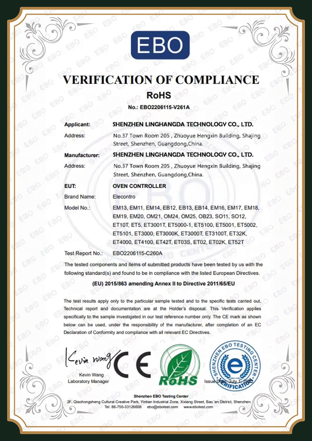
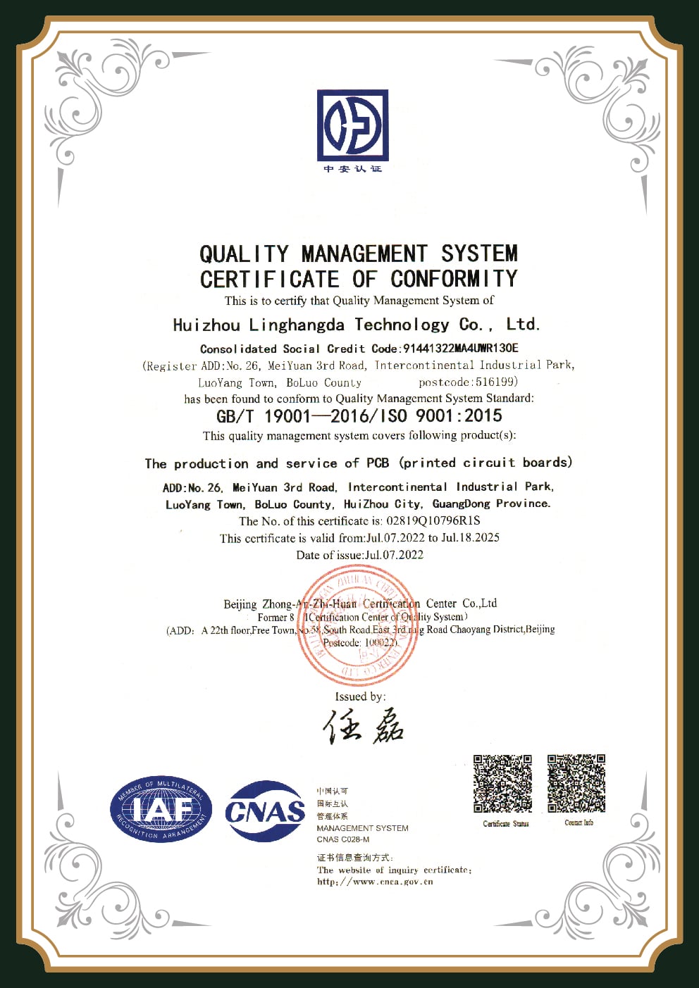
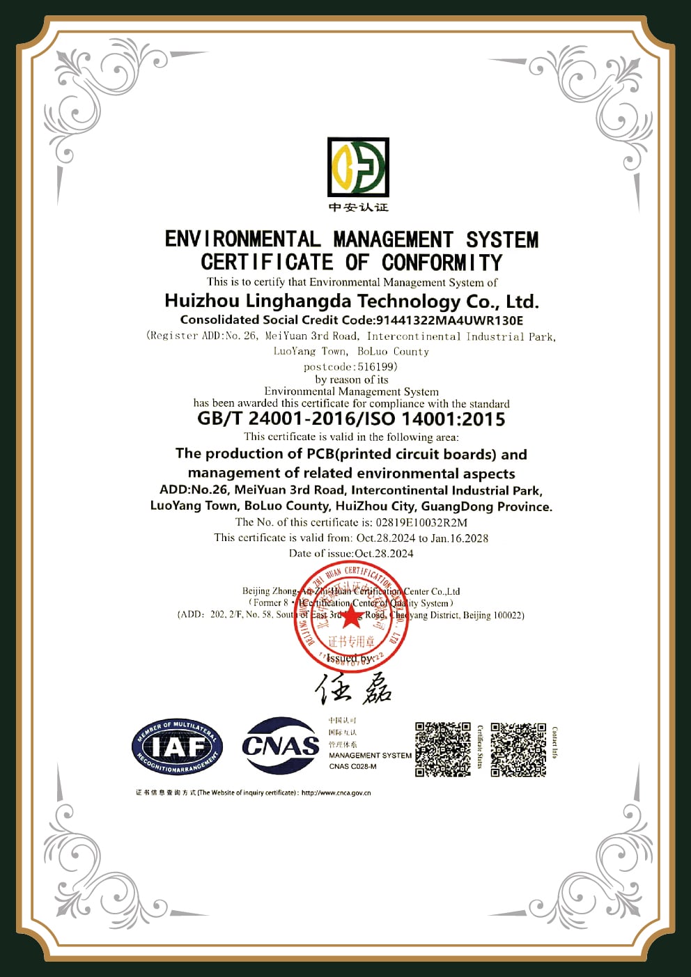
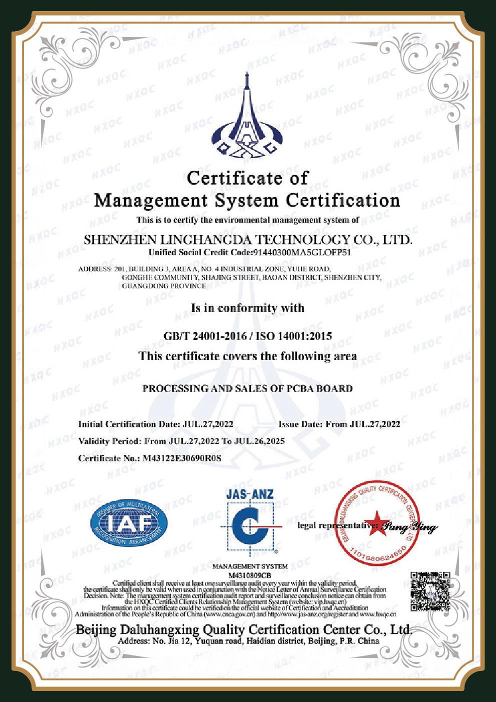
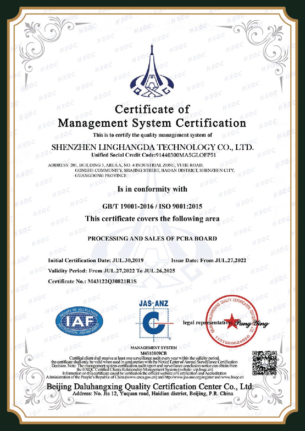
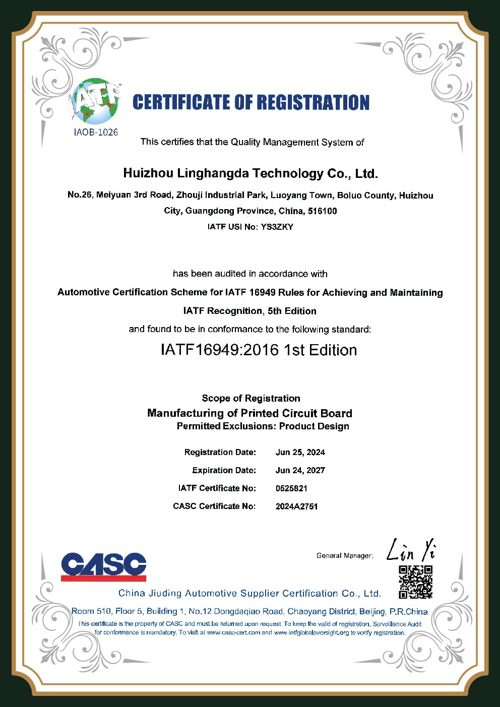
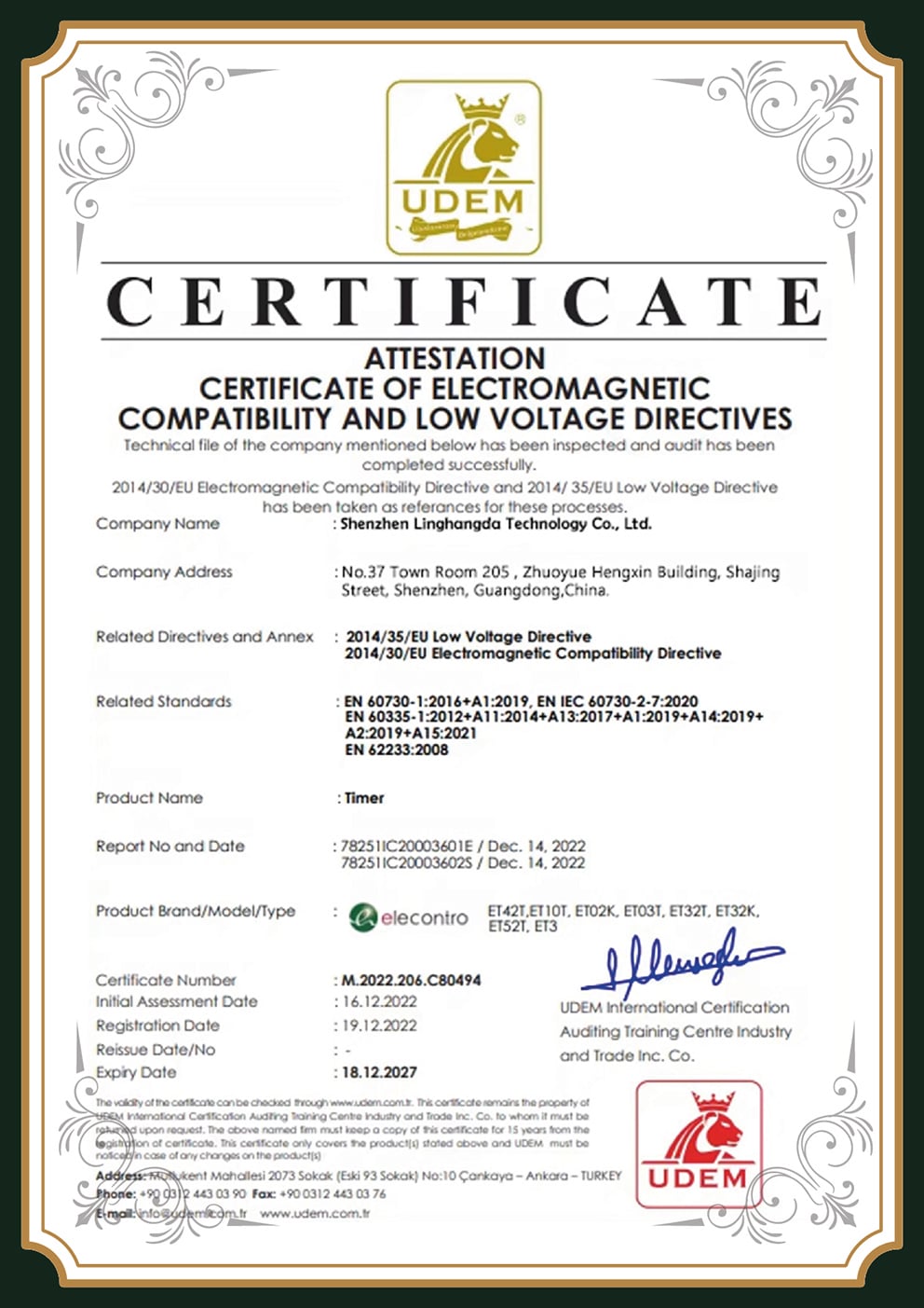
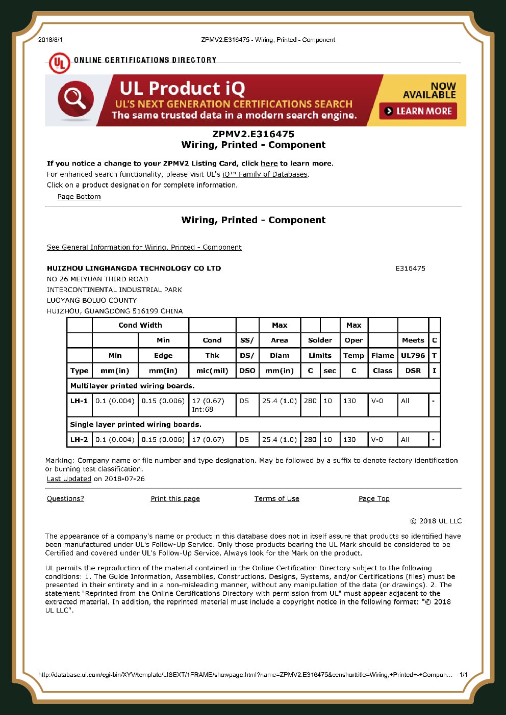
With the potential mission-critical nature of robotics, a certification isn’t just for show-it’s your audit trail into a supplier’s ability to produce a quality part under rigorous, mission-essential conditions.PCBark robotics board assembly and production is documented against the following quality standards:
IATF 16949
Automotive-grade reliability
ISO 9001
Quality management
ISO 14001
Environmental management
UL
Listed PCB / safety
IPC-A-610 2/3
Assembly acceptance
RoHS / REACH
Materials compliance
Automotive-grade IATF 16949 is the roboticists’ certification of choice. Designed for parts that simply can’t fail due to the environmental stress-vibrations and heat cycling-that’s common in mobile or in-vehicle robotic environments, IATF 16949 coupled with IPC-A-610 Class 3 standards offers a zero-defect- not a best-effort-process for our most demanding customers.
Applications
Robotics Applications We Power
PCBark’s robotics work is one application within our broader EMS operations. It ships to more than 2,000 global end-users across 16+ years, which gives a new robotics program a scalable roadmap built on a mature, documented process – not a learning curve whose mistakes you pay for. A field failure in a deployed medical or industrial robot risks costly recalls, which is why IATF 16949 process control and 100% traceability are standard on every robotics PCB we build. Unlike a fab still learning robotics, that rigor is in place today.

Industrial robots & arms
Motion-control and power boards for repetitive, high-duty factory automation — often built alongside our industrial control PCBs.
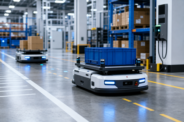
AGV & AMR
Navigation, battery management and sensor-fusion boards for mobile robots.

Medical & surgical robots
Class 3 boards where reliability is non-negotiable and traceability is audited.
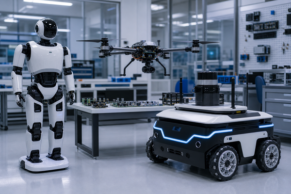
Drones, humanoids & service bots
Lightweight HDI, flex and rigid-flex for weight- and space-constrained platforms, from humanoid robots to compact service bots.
Procurement & Cost
Procurement Guide, Lead Time, MOQ, Files & Total Cost
It’s very often the case that the cheapest quotation isn’t the lowest total program cost. The uncounted cost of robotics PCB assembly or manufacturing-work not to spec, board respin, counterfeiting-is too large for an unprepared vendor to withstand. Honest cost consideration includes:
Pricing Factors Framework, What Actually Drives Your Quote
VAR 01
Board material (e.g., rigid, rigid-flex, HDI) and layer count.
VAR 02
Assembly build level (e.g., IPC-A-610 Class 2, or Class 3 which adds significant reliability for 100% inspection).
VAR 03
Sourcing approach: bare board, customer provided components, or full turnkey sourcing and assembly.
VAR 04
Production volumes-prototype, low volume and high volume production-each alter piece-price cost and process requirements.
VAR 05
Testing Depth: AOI is standard but add X-Ray and functional test for ultimate confidence and traceability of every unit against your fixture and process specifications.
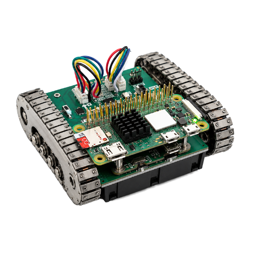
From a custom PCB for robotics prototype to mid volume robotics PCB assembly and mass production, PCBark runs one established process documented against IATF 16949 – so your boards aren’t re-qualified when you scale, with no compromise in quality to hit a cost target. As with all our work, the cheapest bid rarely means the lowest total cost. Send us your design and we’ll quote against your actual requirements rather than a flat price-per-board.
Buyer Advisory, Total Cost of Ownership Over a Cheap Quote
Industry analysis sets the quality-adjusted cost to have a low-batch-consigned part delivered installed, after rework, at 15-30% of the total cost on top of that, and a fielded fake at over $1,000 per unit: a slightly higher-priced board translates to a lower program cost through turnkey sourcing, lot-code traceability, and DFM-driven first-pass yield.
Interactive Utilities
Engineering Calculators & Selectors
Build Your Robotics PCB With a Single Reliable Partner
From DFM review to traceable turnkey assembly, PCBark takes your robot’s electronics from prototype to production on one documented, certified line.
Get a Robotics PCB Quote
Knowledge Base
Robotics PCB FAQ
What makes a robotics PCB different from a standard PCB?
A robotics PCB is built to survive what a consumer board never sees: constant vibration from motors and actuators, concentrated heat at the joints, and duty cycles measured in years rather than warranty periods. In practice that means a higher IPC class, vibration-resistant solder and component staking, thermal-via or metal-core heat paths, conformal coating against moisture and dust, and lot-code traceability on every part, a stack of control a standard consumer board simply skips because it never has to earn them.
What types of PCBs are used in robotics?
Rigid multilayer and HDI for control and AI compute, flex and FPC for sensors and moving joints, rigid-flex to replace connectors in limbs, metal-core for motor drivers, and high-frequency laminates for radar and LiDAR.
What certifications matter for robotics PCB manufacturing?
IATF 16949 (automotive-grade reliability under vibration and heat), ISO 9001, UL, and IPC-A-610 Class 2/3 for assembly acceptance. For surgical or mission-critical robots, insist on Class 3 with 100% inspection.
What is the MOQ, can you do both prototype and volume?
Yes. We run quick-turn prototypes for validation and scale the same documented process to mid-volume and mass production, so your board isn’t re-qualified when you move to volume. Contact us for tier-specific pricing.
What files do you need for a robotics PCB quote?
Gerber or ODB++, a BOM with manufacturer part numbers, and pick-and-place data. Stackup and impedance targets help.
How do you ensure component authenticity and traceability?
We source through authorized distributors (Arrow, Avnet, DigiKey) with lot-code traceability and AS5553-aligned counterfeit avoidance. If a supplier can’t show traceability, the safe answer is to walk away, so we make it standard.
Can a China-based factory reliably support overseas robotics projects?
Reliability comes from process control, not postcode. PCBark runs IATF 16949 and IPC-A-610 Class 2/3 with documented inspection and traceability, ships to 2,000+ global end-users, and supports projects in English from quote to delivery.