Get in touch with PCBark Company

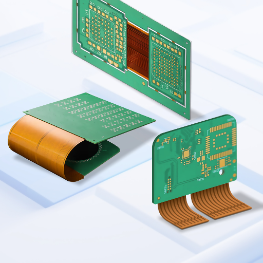
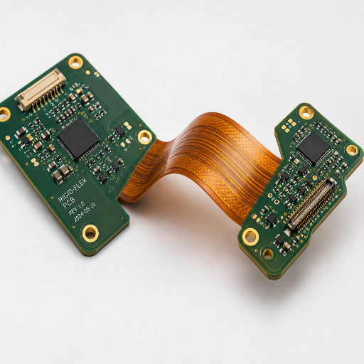
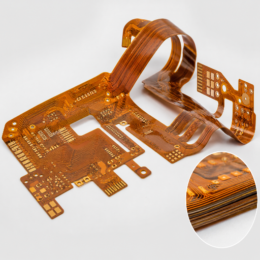
The Flex PCB Premium-Price Problem, and How PCBark Sources
Search “flex pcb” and the first question the results surface is always the same: why are flex PCBs so expensive? A flexible printed circuit costs more than a rigid board because polyimide film, rolled-annealed copper, coverlay lamination, and the lower yield of bending-grade materials all stack onto the bill, before a single component is placed. The same construction logic underpins decades of flex circuit patents, including the bending-region assembly described in US 6,927,344 B1.
Here’s the honest trade-off most vendors skip: that premium is real per piece, but the part of the price you actually control is sourcing and design, not the laws of materials science. PCBark is a China-based EMS, founded in 2010, running a 500,000 m²/year facility, that publishes the full capability band, builds to IPC-6013 Class 2/3, and 100% electrically tests every flex and rigid-flex board.
Real buyers say the quiet part out loud. On r/PrintedCircuitBoard, one engineer put it plainly: “FPCs are more expensive and yield rates are low… with FPC your design will likely determine quality.” That’s the thread running through this page.
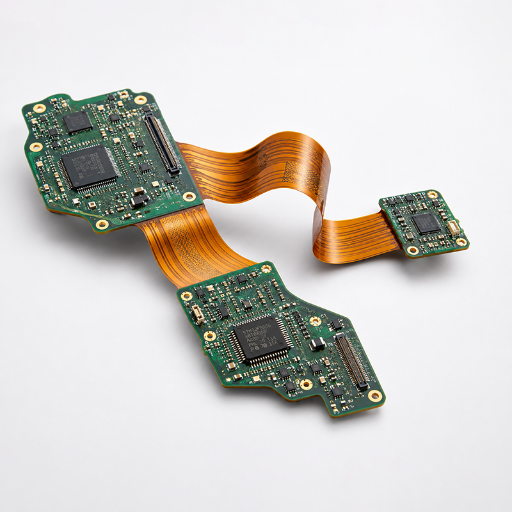
Rigid-Flex PCB Manufacturer
4–24+ layers · 1–6 flex layers · HDI + via-in-pad · ENEPIG
Rigid zones for connectors and BGAs, flex zones to fold into the enclosure, one board, no internal cabling.
Explore rigid-flex PCB manufacturing →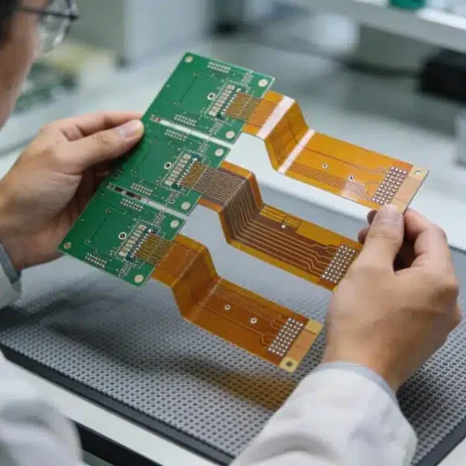
Flexible PCB Manufacturer (FPC)
1–10+ layers · PI / adhesiveless · RA copper · coverlay
Single- and double-sided flexible printed circuits that replace bulky wiring in wearables, sensors, and displays.
See our flex pcb fabrication capability →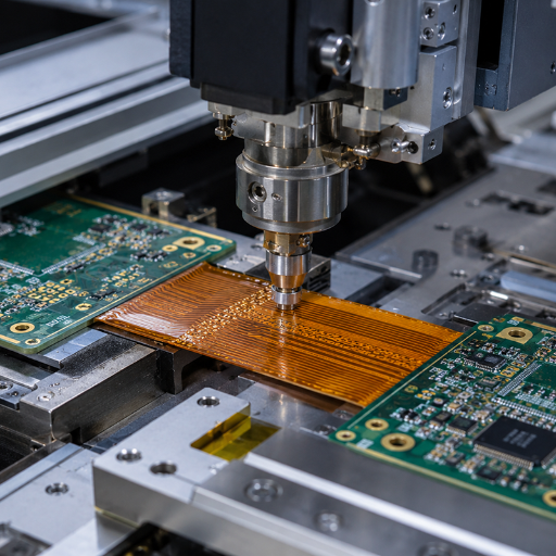
Flex PCB Assembly
SMT on flex · stiffener-supported · AOI + flying probe
Turnkey flex pcb assembly with fixtured stiffeners so thin boards stay flat and registered through reflow.
View flex PCB assembly →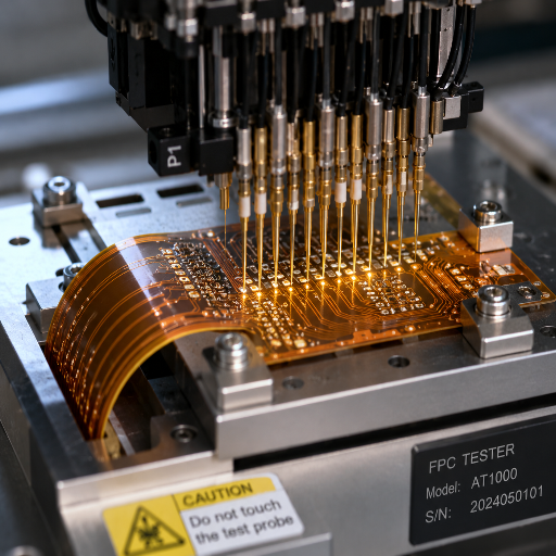
Multilayer Flex PCB (4–12 Layer)
Staggered traces · cross-hatch flex zones · controlled impedance
Higher layer counts for dense interconnect where a single- or double-sided flex board runs out of routing room.
Configure a multilayer flex pcb →
Capability Envelope
PCBark Flex and Rigid-Flex Specifications
Engineers don’t want “high quality” — they want the number. Competitor flex pages share one revealing gap: the highest-ranking result for “flex pcb” ships no spec table at all. Below is the Flex and Rigid-Flex Capability Envelope: PCBark’s own production band across three tiers, so you can match your design to a tier before you ever request a quote. These are factory capability figures, not catalog aspirations, including copper plating thickness, the high temperature rating of the polyimide film (rated to +200°C), and the polyester (Mylar) option for lower-temperature, lower-cost builds. Its material backbone, polyimide on rolled-annealed copper, is the same chemistry recognized across flexible-electronics patents such as the thin multi-chip flex module of US 2011/0116244 A1 and certified to our ISO 9001:2015 quality system.
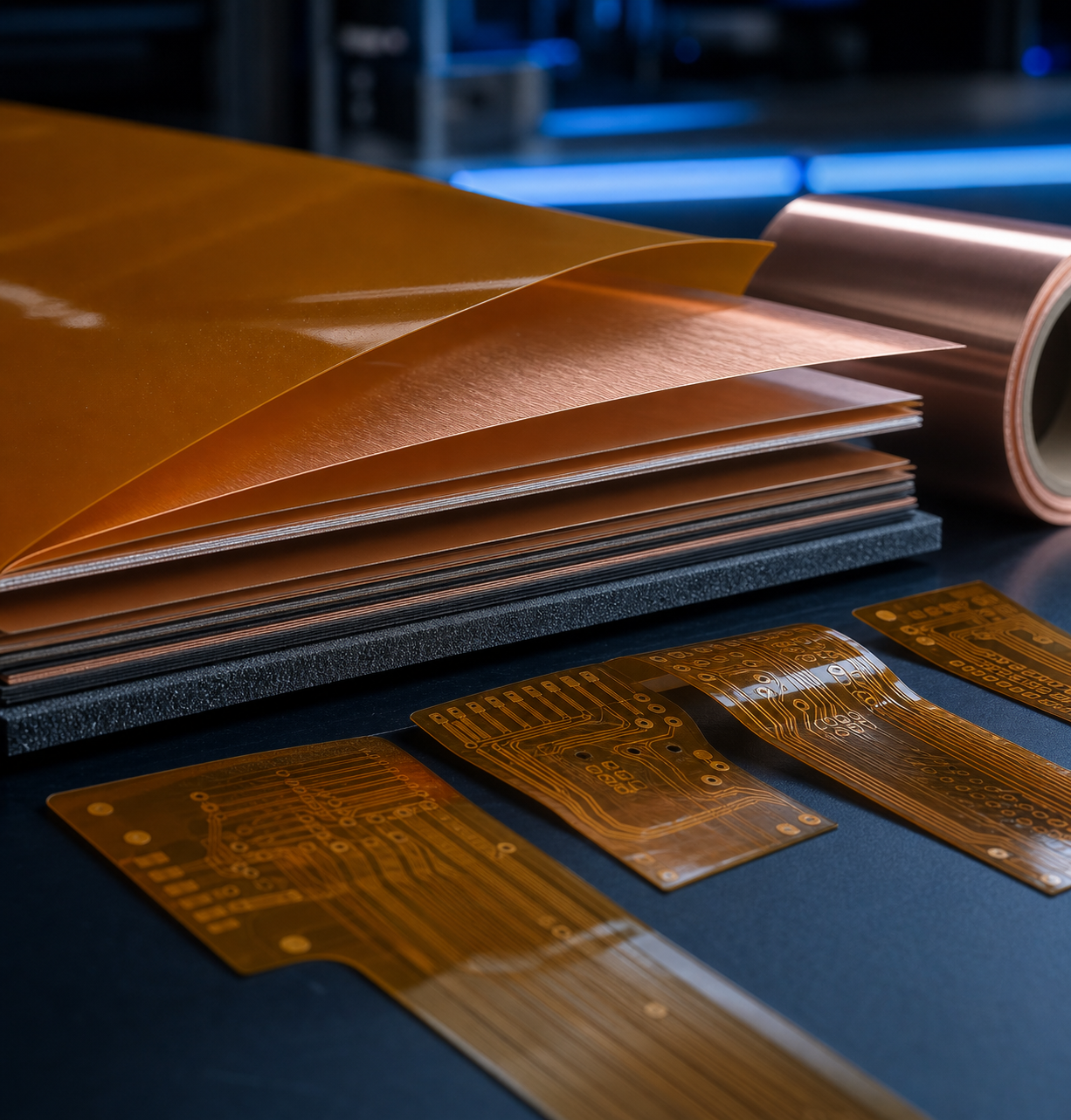
FPC: Materials & Baseline Capabilities
| No. | Parameter (Materials) | Standard | Advanced | Maximum |
|---|---|---|---|---|
| 1 | Layer count | 1–2 | 2–6 | 10+ |
| 2 | Base material | PI / polyimide | PI, adhesiveless | High-reliability flex |
| 3 | Board thickness | 0.08–0.20 mm | 0.05–0.30 mm | Project-based |
| 4 | Copper weight | 0.5–1 oz | 0.5–2 oz | 3 oz |
| 5 | Copper foil type | ED copper | RA copper | High-flex RA copper |
FPC: Precision & Testing Capabilities
| No. | Parameter (Precision) | Standard | Advanced | Maximum |
|---|---|---|---|---|
| 6 | Min trace / space | 0.10 / 0.10 mm | 0.075 / 0.075 mm | 0.050 / 0.050 mm |
| 7 | Min laser via | 0.10 mm | 0.075 mm | 0.050 mm |
| 8 | Surface finish | ENIG, OSP | ENIG, Imm. Silver/Tin | ENEPIG, hard gold |
| 9 | Coverlay | Yellow, black | + white | Custom colors |
| 10 | Stiffener material | PI, FR-4 | + stainless steel | Aluminum, steel, custom |
| 11 | Min bend radius | ≥10× thickness | ≥6× thickness | ≥3× thickness |
| 12 | Dynamic bend cycles | 1,000+ | 10,000+ | 100,000+ |
| 13 | Impedance control | ±10% | ±8% | ±5% |
| 14 | Testing | 100% E-test | + AOI, flying probe | + impedance + reliability |
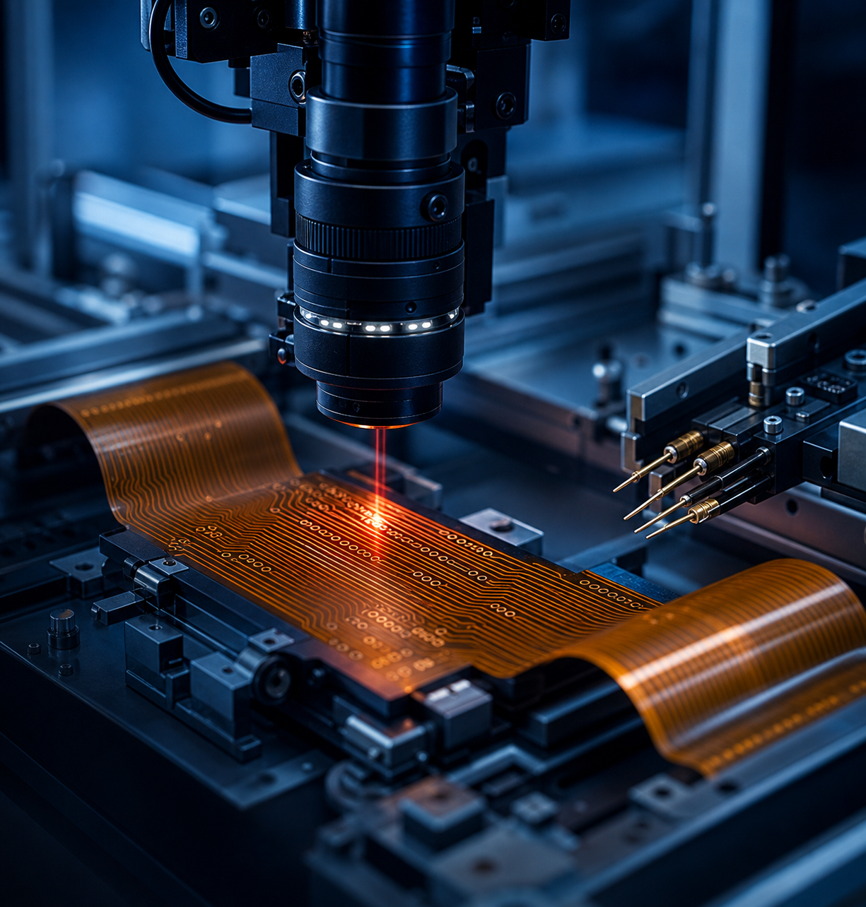
Rigid-Flex PCB Band Capabilities
| No. | Parameter (Rigid-Flex) | Standard | Advanced | Maximum |
|---|---|---|---|---|
| 1 | Total layers | 4–8 | 6–16 | 24+ |
| 2 | Flexible layers | 1–2 | 2–4 | 6 |
| 3 | Rigid layers | 2–6 | 4–12 | 20+ |
| 4 | Base material | FR-4 + PI | High-Tg FR-4 + PI | High-speed + PI hybrid |
| 5 | Rigid area thickness | 0.6–1.6 mm | 0.4–2.4 mm | 3.2 mm |
| 6 | Blind / buried vias | Available | HDI rigid-flex | Multi-step HDI |
| 7 | Via-in-pad | Available | BGA via-in-pad | Fine-pitch BGA |
| 8 | Min trace / space | 0.10 / 0.10 mm | 0.075 / 0.075 mm | 0.050 / 0.050 mm |
| 9 | Min bend radius | ≥10× flex thickness | ≥6× flex thickness | ≥3× flex thickness |
| 10 | Impedance control | ±10% | ±8% | ±5% |
| 11 | Testing | 100% E-test | + AOI, flying probe | + TDR impedance + reliability |
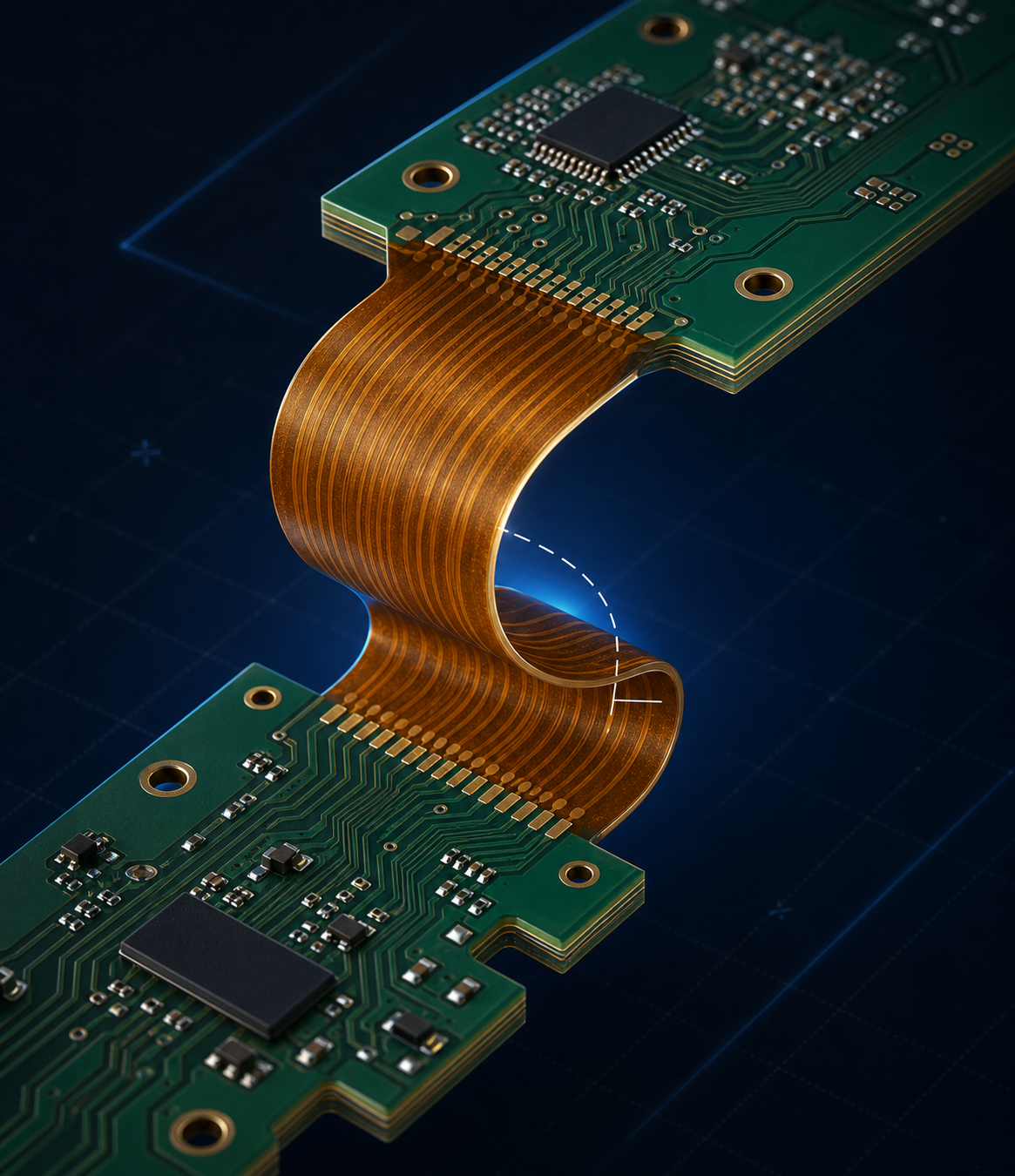
How to read the Envelope
Pick the tightest single parameter your design needs, say 0.075 mm trace, and that one row set your tier. You don’t pay Maximum-tier pricing for a Standard-tier board just because one feature is aggressive; we quote per the controlling parameter, not the worst case.
Flex PCB design notes: materials, layout, and cost
Good flex PCB design starts before fabrication, at PCB layout and circuit design. The base material used in most flexible circuit boards is polyimide flex, a flexible polyimide film, an engineered flexible plastic, carrying a conductive copper layer. That conductive layer is what bends; the flexible dielectric beneath it’s what survives repeated bending. Typical adhesive layers run 1 or 2 mils, and trimming them is one of the most cost effective moves in any flex stack-up.
The common types of flex follow a simple ladder. Single or double sided constructions cover most low-layer work; multiple layers handle dense routing where a single or double sided board runs out of room. Picking the right type of flex, rather than defaulting to multiple layers or copying a multiple design from a past project, is the first lever to reduce cost and control weight and size. Material choice drives the rest: a rigid part on FR4 behaves nothing like the flexible materials used in a dynamic bend, and matching the common material to your circuit needs is where flexible PCB manufacturing experience pays off.
This is the PCB technology that lets one flexible circuit, built as a single flex circuit board, replace a stack of rigid circuit boards and their wiring. Used in flexible, foldable, and wearable products across prototype and production runs alike, custom flex circuitry is sourced from a short list of suppliers of flexible boards using flexible, bend-tested material sets, and the cheapest path is rarely the one with the most board materials or layers.
Single-Sided to Rigid-Flex: The Flex Stack-Up Decoder
Most over-spending on a flex pcb design happens at the construction decision, not the fab. Bend-radius mistakes, over-layering a zone that only need to fold once, or speccing a tight radius the stackup can’t survive, are what turn a clean board into “broken traces, peeled coverlays, and costly field returns.”
The Flex Stack-Up Decoder maps each construction to the job it actually fits. Inkjet and additive flex constructions like WO 2018/132603 A1 are pushing these boundaries, but the four classic families still cover the overwhelming majority of designs.
+ READ MORE
Engineering Note
In the bend zone we route traces perpendicular to the bend axis, stagger top/bottom traces (never stack them into a stiff I-beam), and replace solid copper pours with cross-hatch at roughly 0.38 mm trace / 0.63 mm space per IPC-2223. Vias stay 1.0–1.5 mm clear of the flex zone and stiffeners stay 2.5 mm back. Adhesiveless polyimide and rolled-annealed copper go into any dynamic flex pcb design because they survive repeated bending where adhesive-based ED-copper stacks crack.
01
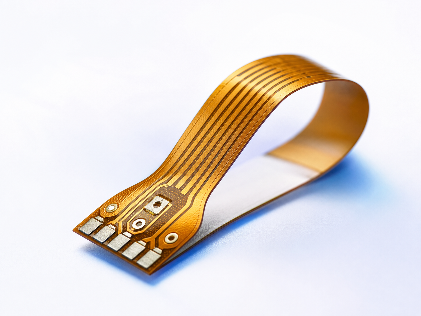
Single-sided FPC
Layers1 copper
Bends well?Best — thinnest, tightest radius
Best forSensor tails, LED strips, dynamic ribbon flex
02
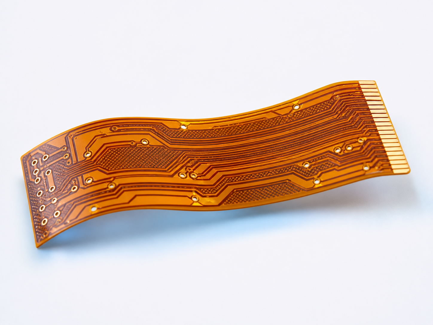
Double-sided FPC
Layers2 copper
Bends well?Good — needs staggered traces
Best forTwo-sided routing, shielding, displays
03
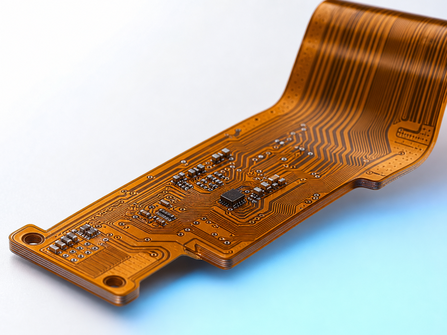
Multilayer flex
Layers3–10
Bends well?Limited — thicker, larger radius
Best forDense interconnect, controlled impedance, static folds
04
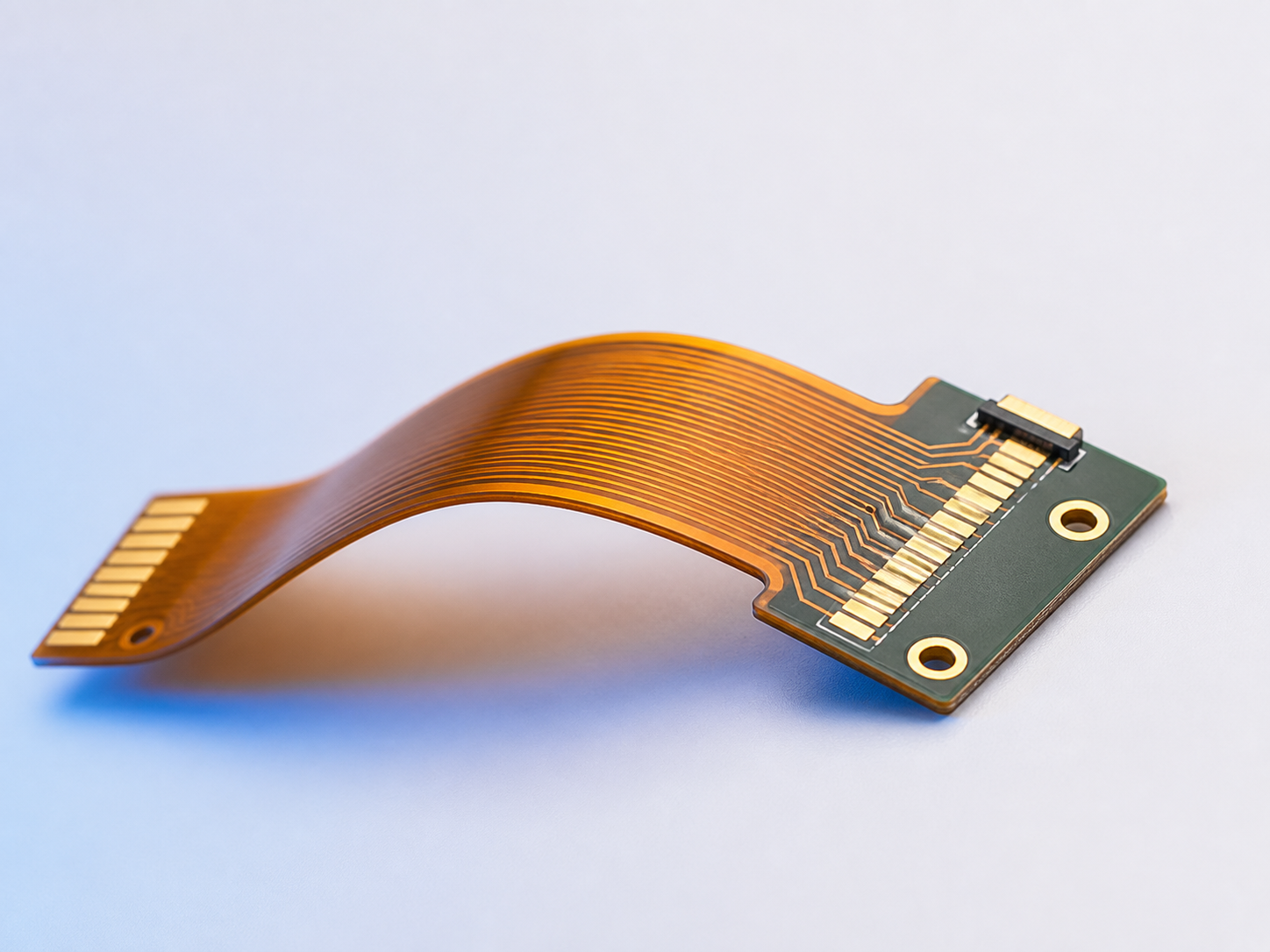
Flex + stiffener
Layers1–n + PI/FR-4
Bends well?Rigid only at stiffened zones
Best forConnector areas, component islands, ZIF tabs
05
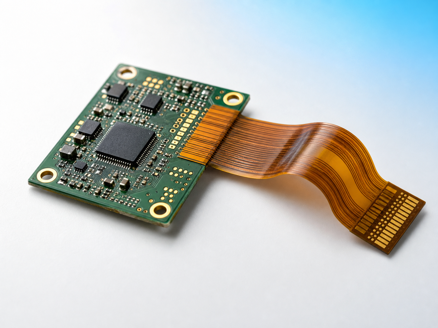
Rigid-flex
Layers4–24+
Bends well?Flex zones only; rigid zones fixed
Best forFold-to-fit modules, BGA + flex in one board
Here's how the Decoder plays out on a real part. A wearable heart-rate monitor we scope routinely splits into two constructions: the sensor tail that flexes against the wrist strap is a single-layer FPC at 0.10 mm, chosen for the tightest radius, while the controller body is a six-layer rigid-flex circuit that folds the battery board against the main board. Picking the right construction per zone, rather than forcing one configuration onto the whole part, is what held that design’s bare-board cost flat while doubling its rated bend life.
What makes that practical is single-sourcing: PCBark runs all five constructions on one line, from single-sided FPC through 24-layer rigid-flex, so a mixed flex and rigid-flex PCB never gets split across two suppliers with two conflicting DFM opinions. A board that delaminates at the rigid-to-flex transition usually fails because no single vendor owned that boundary, here, one team does.
Send Stackup for Free Review ->How Long Will It Bend? The Dynamic Bend-Cycle Endurance Curve
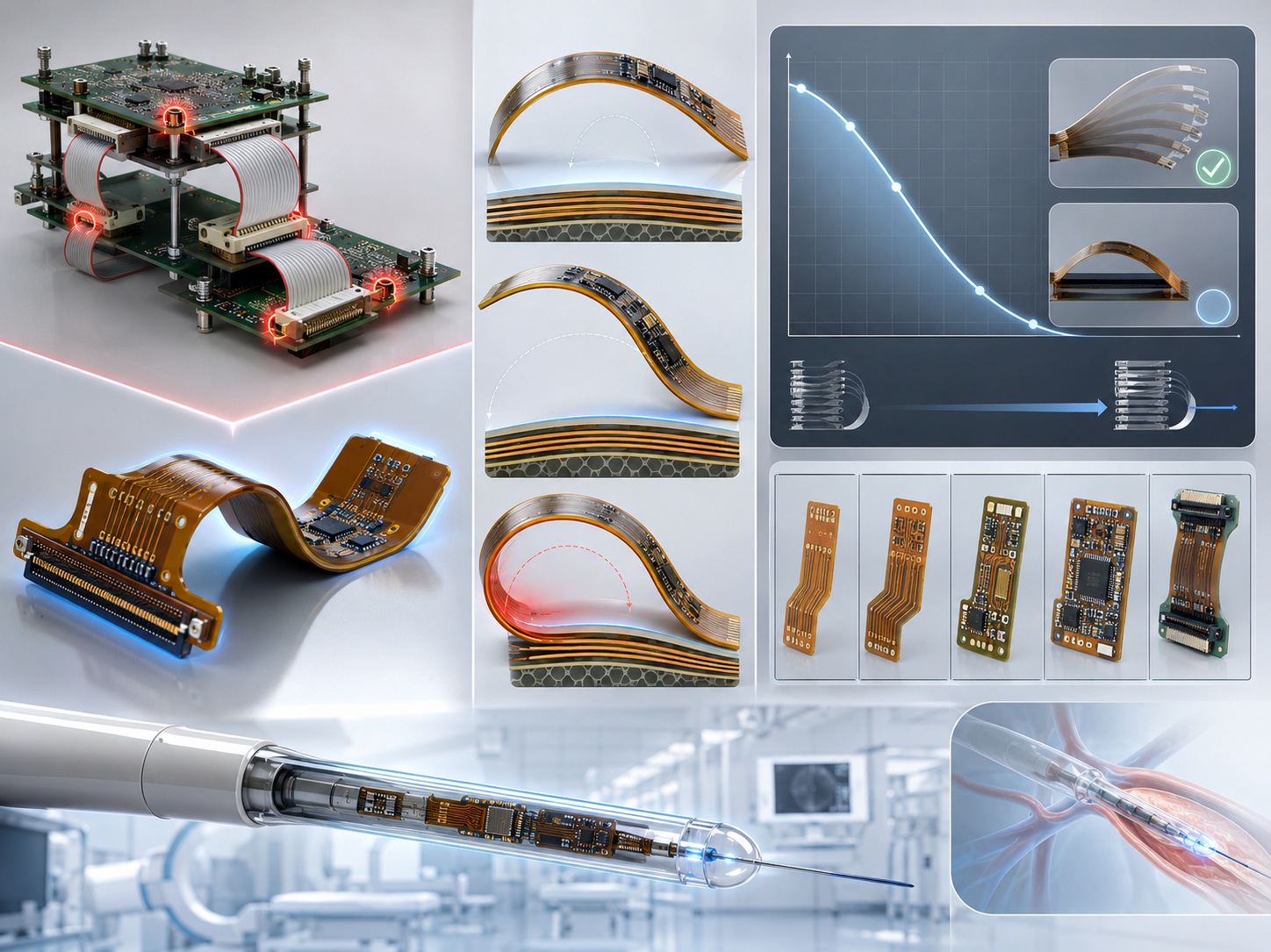
Start with the counter-intuitive part: Rigid-flex has fewer points of failure than the “simpler” alternative, because folding the circuit into one board eliminate the connectors and cables that are the parts most likely to fail in the field. Reliability for a flex circuit isn’t about if it bends, it’s how the bend radius and cycle count line up. Consider the medical-grade catheter flex-PCB of US 10,201,311 B2: it survives inside the human body precisely because that math was respected.
IPC-2223 sets the minimum bend radius as a multiple of total flex thickness, and the gap between a one-time install bend and a repeatedly-flexing hinge is dramatic. This is the Dynamic Bend-Cycle Endurance Curve, the design rule and the PCBark capability tier side by side.
| No. | Bend type | Layers | IPC-2223 min radius | PCBark cycle tier |
|---|---|---|---|---|
| 1 | Static (install once) | 1 | 6× thickness | 1,000+ cycles (Standard) |
| 2 | Static (install once) | 2+ | 12× thickness | 1,000+ cycles (Standard) |
| 3 | Dynamic (repeated flex) | 1 | 100× thickness | 10,000+ cycles (Advanced) |
| 4 | Dynamic (high-cycle hinge) | 2+ | 100–150× thickness | 100,000+ cycles (Maximum) |
“We treat the cycle count as a contract, not a marketing number. A 100,000-cycle hinge gets a 100× radius, rolled-annealed copper, cross-hatched flex zones, and a coupon that we physically flex to failure before the lot ships. If the design asks for a radius the stackup can’t hold, we flag it at DFM, we will not claim a cycle life we haven’t tested for.”
Add a 20–30% safety margin to any calculated minimum, material lot variation and assembly handling add stress your CAD model won’t show. Dynamic boards get rolled-annealed copper only; electrodeposited copper’s columnar grain is brittle under repeated bending. Every tier is verified to IPC-6013 with dynamic flex testing per IPC-TM-650 Method 2.4.3.
Upload your flex zone for a free bend-radius DFM check →Flex vs Rigid + Cable, and the FPC Cost-Driver Teardown
There is a Common misconception that rigid-flex PCBs are prohibitively expensive. Its piece-price half is true, an industry whitepaper from flex maker Minco puts rigid-flex at roughly seven times the cost of a traditional rigid board per square inch. But piece price is the wrong denominator. Once you delete the connectors, the cable assembly, the mating hardware tracked through our ISO 14001 system, and the assembly labor that joins them, plus the warranty cost of the connection points that fail first, the system often lands cheaper.
~7×
higher piece price for rigid-flex vs a traditional board — before you subtract the connectors, cables, assembly labor, and field failures it eliminates at the system level.
Source: Minco flex-cost whitepaper; system-cost framing per Altium & Epec engineering libraries. We do not publish a single ROI figure because it depends on your part count — request an application-specific estimate.
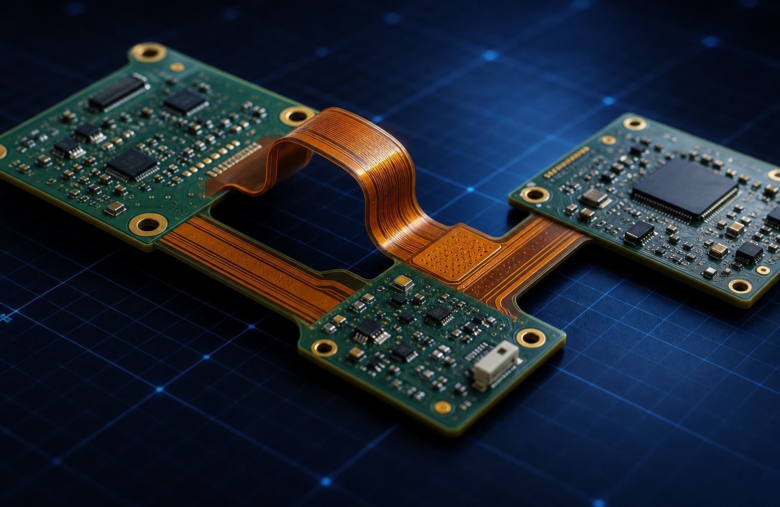
Flex / rigid-flex vs rigid board + cable assembly
| No. | Factor | Rigid board + cable/connector | Flex / rigid-flex |
|---|---|---|---|
| 1 | Piece price | Lower (FR-4 baseline) | ~7× higher per in² |
| 2 | Connection points | Many connectors + solder joints | Folded continuous copper, near-zero connectors |
| 3 | Assembly labor | Manual cable routing & mating | One board, drops into the enclosure |
| 4 | Weight & volume | Higher (connectors + cable bulk) | Polyimide is far lighter than FR-4 |
| 5 | Vibration / field failure | Connectors are the first to fail | Fewer failure points; survives vibration |
| 6 | Best when | Low volume, frequent re-config | Compact, high-reliability, repeated flex |
The FPC Cost-Driver Teardown
The FPC Cost-Driver Teardown shows where the money actually goes, and which levers you control at design time.
| No. | Cost driver | Why it adds cost | How to reduce it |
|---|---|---|---|
| 1 | Material selection | Adhesiveless PI & RA copper cost more than FR-4 | Spec premium material only in the flex zone |
| 2 | Layer count | Each flex layer adds lamination & yield risk | Neck down to fewer layers in the bend zone |
| 3 | Panel utilization | Odd outlines waste panel area | Design to panel; nest with our DFM team |
| 4 | Stiffener type | Steel/aluminum stiffeners add process steps | Use PI/FR-4 stiffeners where rigidity allows |
| 5 | Surface finish | ENEPIG/hard gold cost more than ENIG/OSP | Match finish to the actual contact need |
| 6 | Yield | Flex materials scrap more — baked into price | DFM-clean designs lift first-pass yield |
Built to IPC-6013, Standards, Classes & Honest Scope
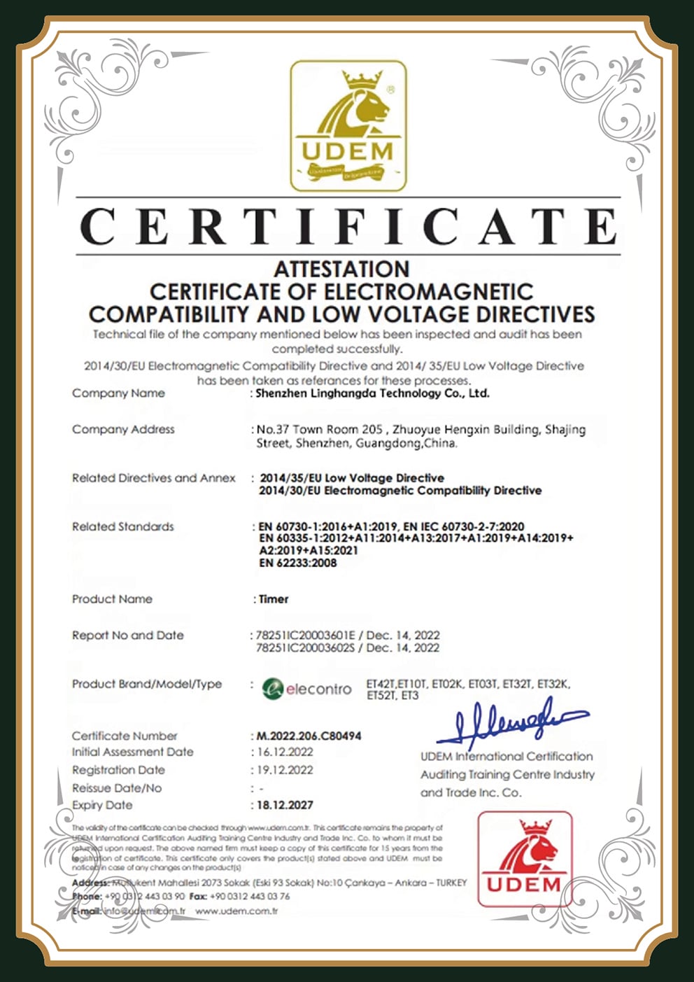
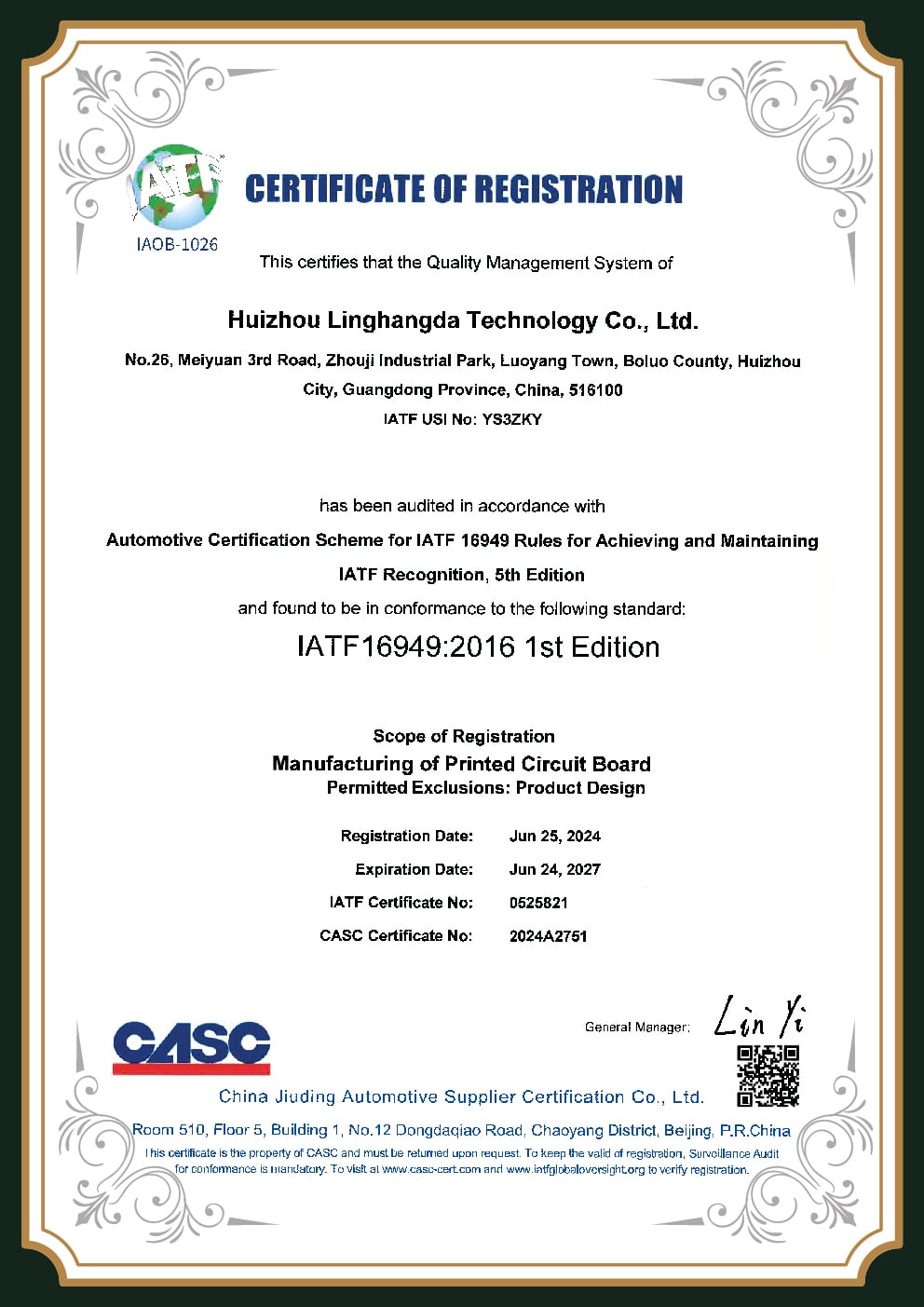
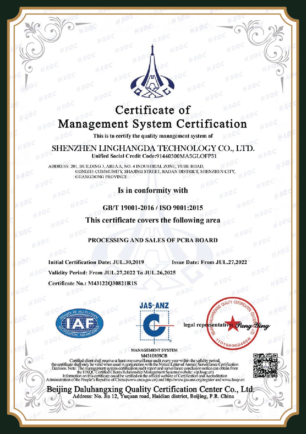
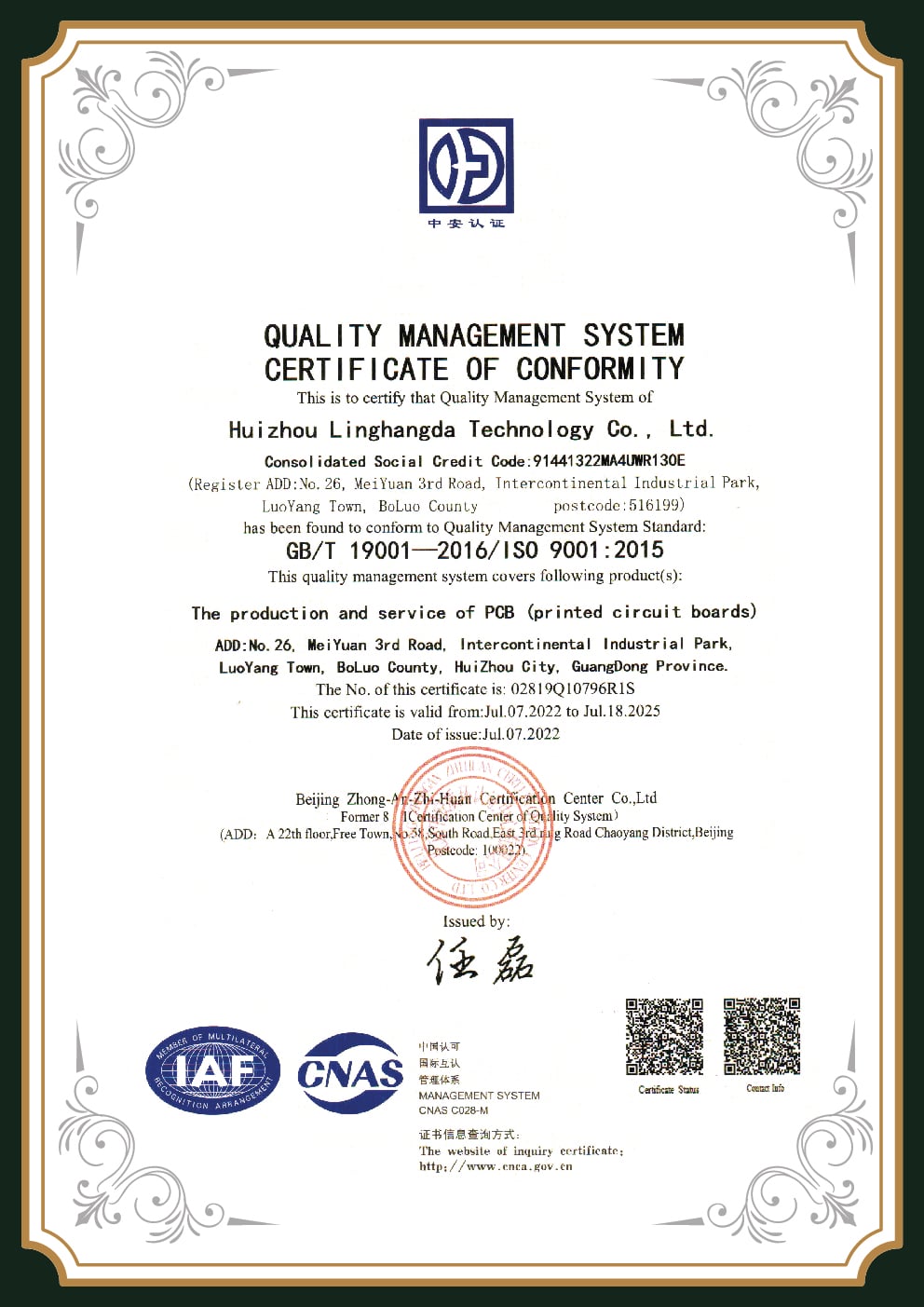
A new supplier with no household name has to answer the trust question with documents, not adjectives. Here is the reassuring data point: a Reddit builder testing a China flex shop reported it delivered “same quality as other pcbs from China” at a reasonable price, China-sourced flex is viable when the factory builds to a class and tests every board. We build flexible and rigid-flex boards to the standard that governs them, IPC-6013, the Qualification and Performance Specification for Flexible/Rigid-Flexible Printed Boards, and designs to IPC-2223. Our quality system is certified to ISO 9001:2015.
The Honest Scope
Here's the honest part competitors blur: building to a standard and holding a certificate are different claims. PCBark builds flex and rigid-flex to IPC-6013 Class 2/3 and tests to it; we won't claim AS9100 or ITAR registration we don’t hold. If your program needs an aerospace or defense certificate beyond our scope, we tell you up front rather than after the PO. That's the kind of supplier honesty that survives an audit. See our full certification stack and inspection methods.
| No. | IPC-6013 class | Reliability level | Typical use |
|---|---|---|---|
| 1 | Class 1 | General | Consumer electronics |
| 2 | Class 2 | Dedicated service | Industrial, communications |
| 3 | Class 3 | High reliability | Medical, automotive, aerospace |
IPC-6013Class 2/3 build
IPC-2223Flex design rules
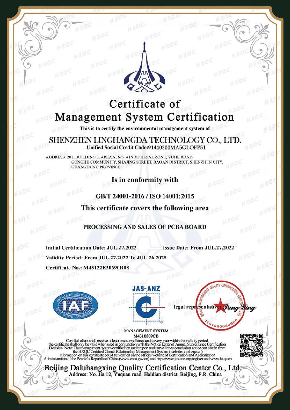
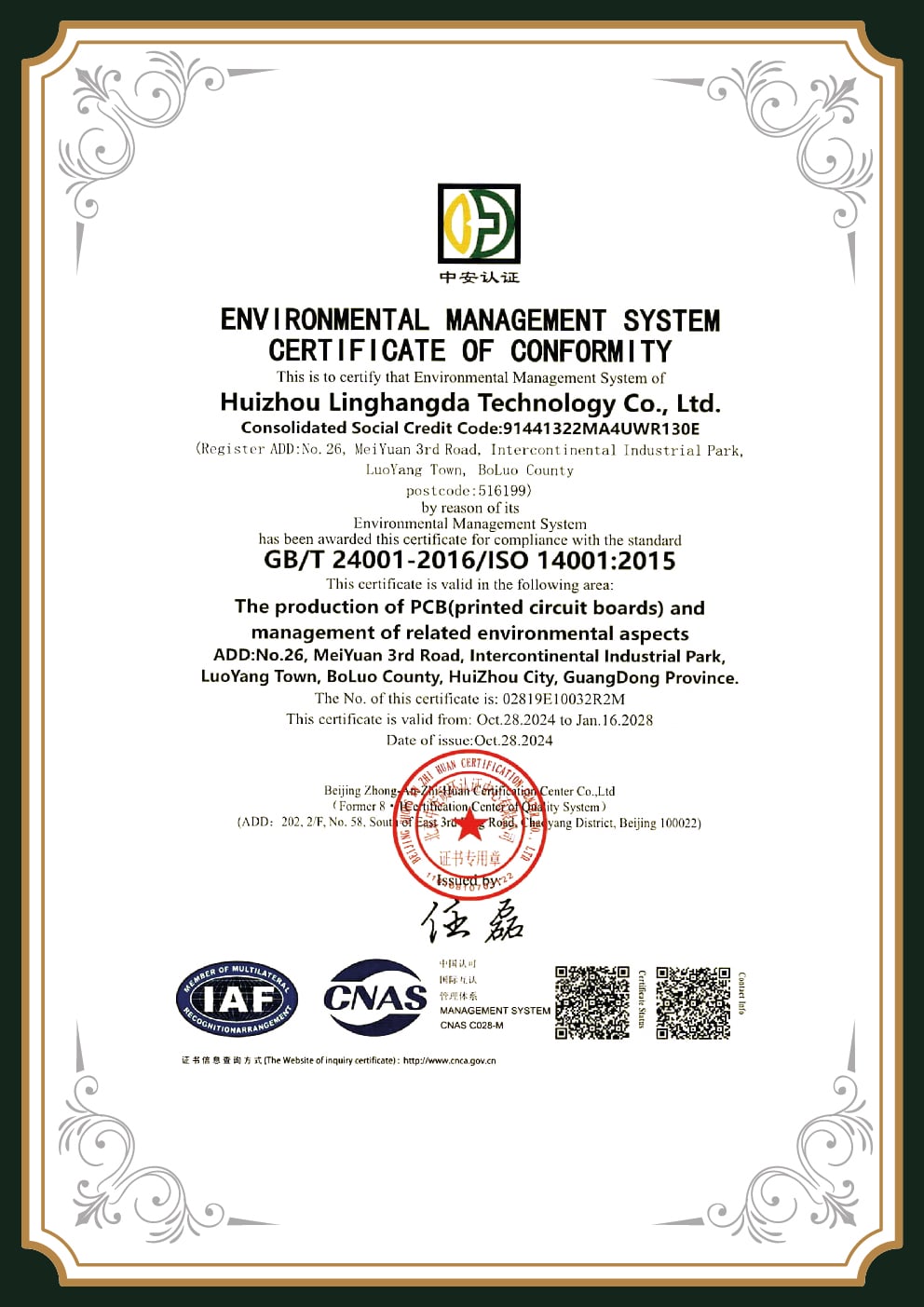
ISO 9001:2015Quality system
ISO 14001Environmental
IPC-A-610Class 2/3 accept.
J-STD-001Soldering
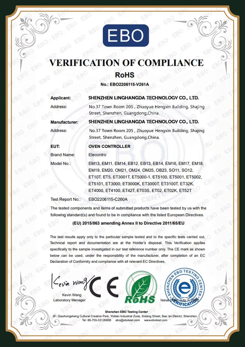
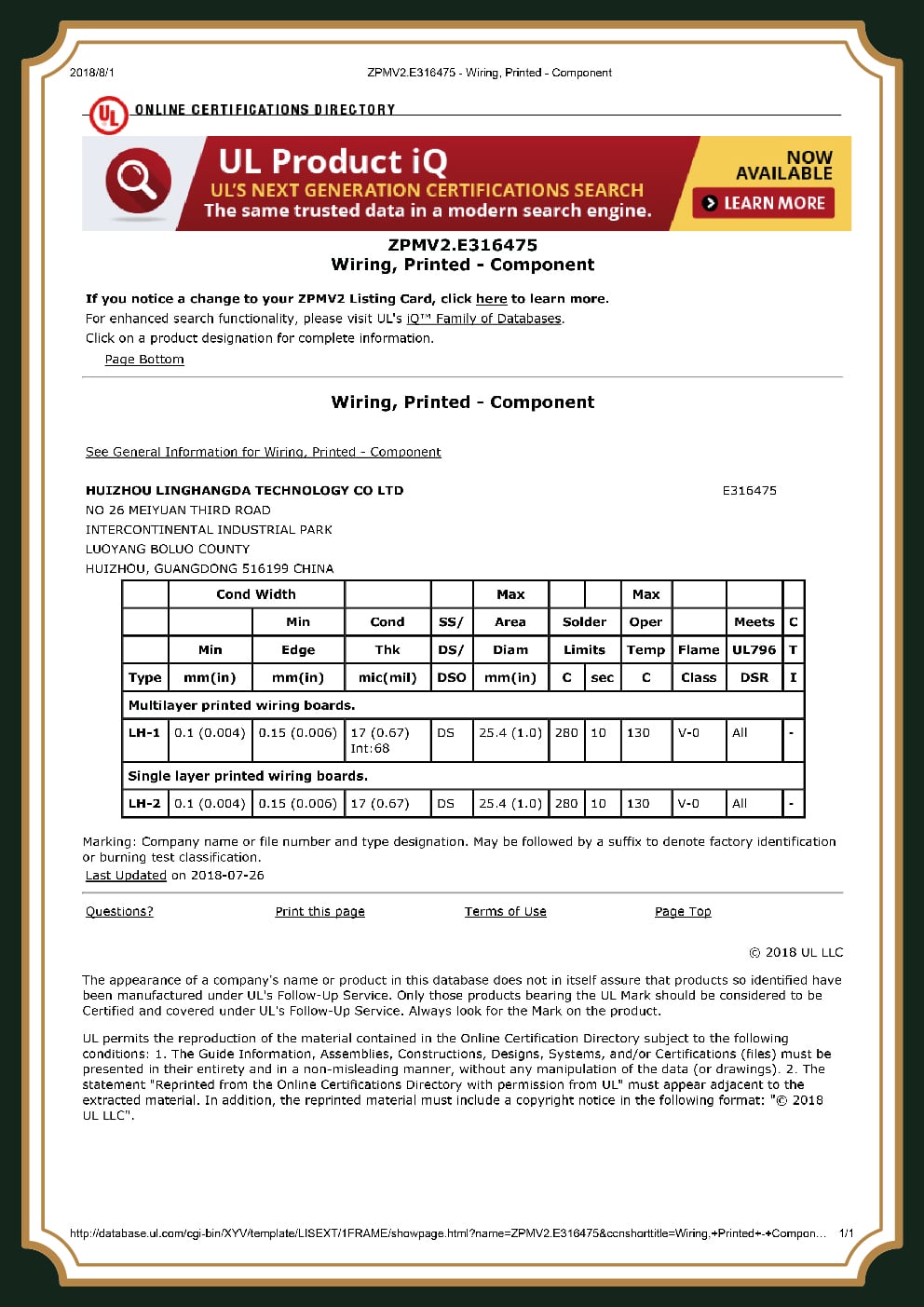
UL / RoHSREACH compliant
❮
01 / 08
❯
×
![Certificate Detail Visualizer]()
FAQ: Flex & Rigid-Flex PCBs
Why are flex PCBs so expensive?
Flex PCBs cost more because the materials are pricier and harder to process: adhesiveless polyimide and rolled-annealed copper cost more than FR-4, coverlay lamination adds process steps, and bending-grade materials scrap at higher rates that get baked straight into the unit price. As engineers on Reddit repeatedly point out, low FPC yield is a core driver, and the biggest swing factors you actually control are layer count, material tier, and how clean the layout is, not the base chemistry itself.
What is the difference between flex and rigid PCB?
A rigid PCB sits on stiff FR-4 and keeps its shape; a flex PCB uses a thin polyimide film that bends without cracking, protected by a coverlay instead of solder mask. Rigid boards suit fixed layouts; flex and rigid-flex suit compact or repeatedly-flexing designs.
What is coverlay in a flex PCB?
Coverlay is the flex equivalent of solder mask: a thin polyimide film, adhesive-backed, laminated over the copper to protect traces from oxidation, moisture, and abrasion. Its laser-cut openings must stay clean and bubble-free, because any gap becomes a stress point where a crack can start.
Unlike the liquid solder mask sprayed onto a rigid board, coverlay is a discrete film that has to be aligned and pressed, so registration tolerance and lamination quality directly set how well a finished flex circuit survives repeated flexing. On dynamic boards we specify polyimide coverlay over acrylic adhesive precisely because it tolerates the high temperature of reflow and the fatigue of a hinge that open tens of thousands of times.
How much does a flex PCB cost compared to a rigid board?
As a rule of thumb, a rigid-flex board runs about seven times the piece price of a comparable rigid PCB per square inch. That number flips at the system level once the board removes connectors, cables, and assembly labor, so compare total assembled cost rather than bare-board price.
When should I choose rigid-flex instead of separate rigid boards plus a cable?
Choose rigid-flex when space is tight, weight matters, or reliability is critical, folding the circuit into one board removes the connectors and cables that are the first things to fail under vibration. Stay with separate boards plus an off-the-shelf cable for low volumes or designs you expect to reconfigure often, where the rigid-flex tooling premium never gets recovered across the run. The break-even almost always comes down to how many connections you delete.
Can a China manufacturer build reliable rigid-flex PCBs?
Yes, reliability comes from building to a class and testing every board, not from geography. PCBark builds to IPC-6013 Class 2/3, designs to IPC-2223, 100% electrically tests every board, and flexes dynamic coupons to failure before a lot ships. The honest qualifier is scope: we hold ISO 9001 and IPC-class processes, and we tell you up front if a program needs a certificate beyond what we carry.