Get in touch with PCBark Company

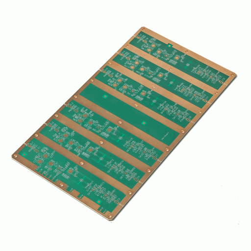
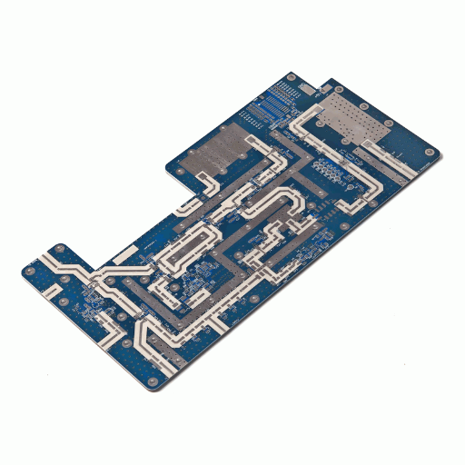
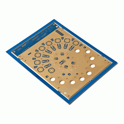
When Your Signal Dies in the Trace: The High-Frequency Loss Problem
Conductor and dielectric loss at microwave frequencies is characterized in IEEE microwave-engineering literature.
Even a perfectly routable 2oz copper at 500 mils is a challenging piece of PCB fabrication because controlling the trace dimensions, stack-up, and tolerance for any variation.
We strive to control tolerances very closely for any 2oz traces we can do on a flat 5 mil substrate, especially if you’re dealing with a more complex stackup…
…however if impedance really is important we might want a 1oz trace, or 0.5oz trace, or possibly to reduce width to .180 inches or.190 inches.
In most modern PCB designs with standard frequency range and substrate, these are all standard on all materials; in designs utilizing higher or specialized materials the challenge to get the ideal width gets higher.
Radio frequency and high-frequency circuits that demand reliable, precise electrical characteristics need advanced materials and precision manufacturing techniques.
Where standard FR-4 based substrates break down due to poor signal integrity (loss tangent of ~0.02), RF laminates like Rogers and PTFE-based composites excel.
These specialized materials offer low loss tangents (as low as 0.001-0.003), and stable dielectric constants (Dk) across a broad frequency spectrum. Our expertise ensure that your design requirements are met from the initial schematic to the final product.
From your low- GHz to high-speed and microwave designs, our state-of-the-art fabrication facilities and experienced engineers provide the highest quality solutions to meet all your challenging application needs.
At PCBark, we not only engineer custom solutions but we understand the physics of why it works. You can rely on our ability to meet strict design parameters without compromising quality or reliability.
We specialize in providing high-quality PCB’s for: medical device telemetry, high speed digital devices, communication networks and telecommunications devices, medical equipment’s, radar systems for aviation and automobile, defense electronics, instrumentation, computer storage and networking hardware. Get this right the first time and avoid costly re-designs and schedule delays. Our state of the art process and controls ensure you receive what we promised in design.
PCBark RF & Microwave PCB Capabilities, by Frequency Band
Board Characteristics • Reliable Impedance & Loss • Wide range of Frequency.
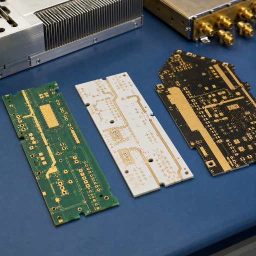
Transmission-line structures we build
RF Laminate Selection: Dk, Df & the Insertion-Loss Budget by Band
Unlike a commodity house, PCBark will not recommend a 77 GHz laminate for a 2.4 GHz board — the right call is the lowest-loss material that still meets your budget, because above 40 GHz copper surface roughness alone can add real insertion loss.
Choosing the base materials and foil you'll use is the one selection you'll make that drives virtually every subsequent design decision, and subsequent risk: you choose the material primarily for two parameters - the dielectric constant (Dk), which sets the physical dimension of your traces, and the dissipation factor (Df, or loss tangent), which dictates how much your signal is attenuated at frequency. Our Insertion-Loss Budget Planner table of Frequency Band & Material matches the allowed loss in dollars for any given band up to 77 GHz to a specific material selection.
| Material | Dk @10 GHz | Df @10 GHz | Best band | Why it earns its place |
|---|---|---|---|---|
| RT/duroid 5880 | 2.20 | 0.0009 | 40–77 GHz+ | Lowest loss; mmWave radar & SatCom |
| RO3003 | 3.00 | 0.0010 | 24–77 GHz | Stable Dk for automotive radar |
| RO4003C | 3.38 | 0.0027 | 2–40 GHz | Low loss, FR-4-compatible processing |
| Isola I-Tera MT40 | 3.45 | 0.0031 | 2–30 GHz | Cost-balanced RF/MW |
| RO4350B | 3.48 | 0.0037 | 2–25 GHz | UL 94V-0 rated; power/transmit |
| Megtron 6 | 3.35 | 0.0040 | 1–25 GHz | High-speed digital + RF hybrid |
| Standard FR-4 | 4.2–4.8 | ~0.020 | <2 GHz only | Baseline cost; loses past 6 GHz |
Engineering note, copper roughness at mmWave
At 77 GHz, just the choice of base material isn't enough. Your actual conductor surface roughness can easily add 25-45% more signal loss to your 77 GHz transmission lines...
...compared to smoother conductor choices. Above 40 GHz, we always use reverse-treated (LoPro-class) copper foil, which can reduce conductor loss about 10-15% by lowering the conductivity of the copper surface at the dielectric interface, which is enough that a given board layout may or may not meet its target gain specification on an 88-patch array, but will on an appropriately routed 77 GHz radar front-end.
Final warning for engineers building high frequency boards:
it’s a misconception that heavier copper always performs better on a high frequency board. If overdone, excessive copper can contribute to stress and warpage...
...and can introduce trace-to-trace impedance variability; we apply copper thickess specifically matching the current capacity and impedance target, not a standard or a guess. If using a laminate rated to IPC-4103, the industry standard for high-speed and high-frequency laminates, which holds Dk variation within about ±0.05 across 1–20 GHz on qualified materials it's simply too thick or not specified to the correct performance characteristic for the circuit design's impedance requirements.
While your commodity PCB house is stocking one or two laminates
PCBark maintains an in-house ISO 9001 of Rogers, Isola, Taconic, Arlon, and PTFE/Teflon hydrocarbon-ceramic high frequency laminates...
...and will check your field-solver's Dk (loss tangent) for you before we build it - the good news: your field-solver was right; the bad news: a mismatched 0.0027 vs 0.020 is your headache. The CTE is matched across hybrid layers. Single-ended and differential impedance is tuned per material. The correct choice isn't the cheapest one on the shelf; it’s the one that meets its loss budget at YOUR frequency - and we won't unnecessarily force a 77 GHz laminate onto a 2.4 GHz board.
RF/Microwave PCB vs FR-4, the Break-Even, Not the Dogma
Impedance-matching structures for RF boards are documented in USPTO patent US9331720B2.
Applications: 5G, Radar, Satellite & Millimeter-Wave
RF circuit-board topologies for these systems appear in USPTO patent US20050190614A1.
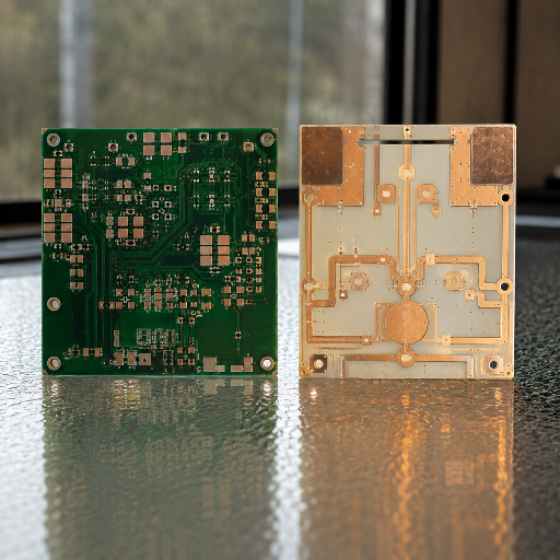
There's never one correct RF laminate, and each RF engineer has a favorite based on what they’re used to. That’s why we've compiled our Microwave Material-to-Application Routing Table which maps use cases to the laminate(s) and frequency(ies) that we use to implement them every day.
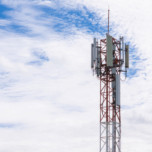
5G base-station antenna & Massive MIMO
Frequency
28 / 39 GHz
Typical material
RO4003C / RO4350B
Critical attribute
Panel-wide Dk uniformity for phase match
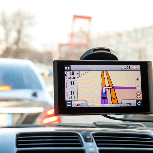
Automotive ADAS radar
Frequency
24 & 77–79 GHz
Typical material
RO3003 / RT-duroid
Critical attribute
Dk stability −40 to +85 °C
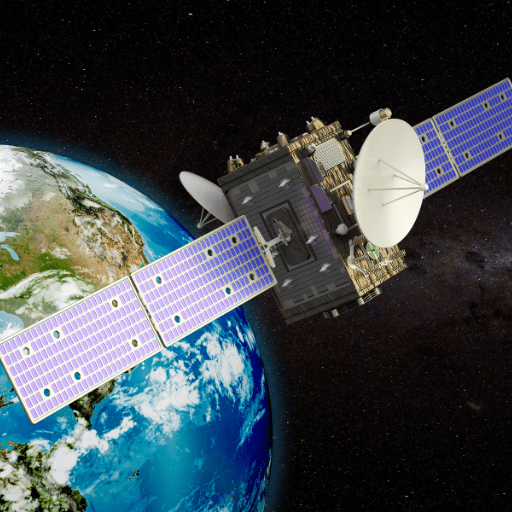
Satellite & SatCom payloads
Frequency
6–40 GHz
Typical material
RT/duroid, ceramic-filled
Critical attribute
Low outgassing, low moisture
RF power amplifiers
Frequency
1–10 GHz
Typical material
RO4350B + heavy copper
Critical attribute
Thermal conductivity + UL 94V-0
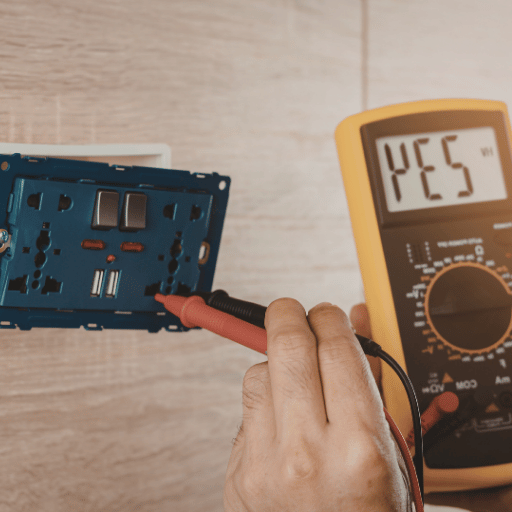
Test & measurement fixtures
Frequency
DC–40 GHz
Typical material
RO4003C
Critical attribute
Tight Dk tolerance (low test error)
At 77 GHz for automotive radar, we see our most demanding applications.
Eighty-eight element patch array with RF35 on a Rogers RO4003C material could reach greater than 20 dBi gain across a GHz bandwidth, but if the via transition losses aren’t on, Dk is stable across the cabin temp range, and copper foil roughness isn’t minimized - the radar won’t work. At this band our Maximum capability set - 32 layers, 5% impedance tolerances, ENIG plating, TDR + RF evaluation - stops being just a specification, and becomes the only reason why it works.
Wrong laminate choice here means costly and late failure - radar passes at RT, then goes out of tolerance at 40 C, and you discover that after tooling.
Unlike a generic fab, PCBark actually quantifies the Dk-versus-temperature trade-off for your band, such that resonant frequency is held across the automotive band - this is the correct choice for safety-critical 77 GHz build, and the structural reason we RF evaluate every mmWave lot.
Advanced RF & Microwave PCB Engineering Tools
RF Material & 50Ω Microstrip Selector
Pick your frequency and substrate height — get a laminate recommendation and an approximate 50Ω trace width. Estimates only; PCBark confirms against a field solver.
Access ToolFR-4 vs Rogers RO4003C — Break-Even Calculator
See the insertion-loss gap and cost trade-off for your design before you commit a material. Estimates anchored to 10 GHz published figures.
Access CalculatorHybrid Stack-up Cost Index Estimator
Compare an all-RF board against a hybrid (RF layers + FR-4) on a relative cost index (FR-4 board = 1.0). Shows why routing RF material only where needed protects budget.
Access EstimatorRF & High Frequency PCB FAQ
A high frequency PCB is used to carry analogue RF/microwave (sinusoidal, GHz range) signals where Dk stability & insertion loss are the key metrics. High speed PCBs are used for high-speed digital edge-rates where edge integrity, timing, & crosstalk are the important variables. The two overlaps in required materials; both need stable low Dk, but the priority on design differ.
Yes, for many designs up to about 6-7 GHz FR-4 should work (and is substantially cheaper). For applications higher than 6 GHz, a loss tangent of around 0.02 and dk drift render FR-4 undesirable, making a low-loss RF laminate the smart choice. Mixed signal builds typically employ hybrid stackups, using FR-4 wherever it’s appropriate and RF laminate only in the locations where high frequency signals or component footprints will exist.
Be specific: Clearly specify desired impedance and tolerance, build a time-domain reflection (TDR) test coupon onto the same panel, and ensure that the factory measure the TDR coupons each lot - not relying on static impedance values based on calculated trace width. All PCBark controlled impedance orders come standard with a TDR test coupon, and high-frequency lots are also tested via VNA on our RF equipment.
Low-Dk, ultra-low-loss laminates such as Rogers RO3003 or RT/duroid are typical for 77 GHz radar, because they hold Dk stable across the automotive temperature range. Pair them with LoPro copper to cut conductor loss at mmWave. Your PCBark designer confirms the exact grade against your gain and bandwidth targets in DFM.
10% for many sub-6 GHz designs, 8% for those operating on Best, and 5% on Maximum builds - all proven via TDR in our system. Ordering tighter tolerances than required - 3% is an example - usually adds more, thus we size your tolerances carefully to maximize performance without over-engineering the production stack up.