
Get in touch with PCBark Company

ISO 9001 & IPC Class 3
Rogers PCB / RF Substrate
Rogers PCB Manufacturer, High-Frequency RF & Microwave Circuit Boards
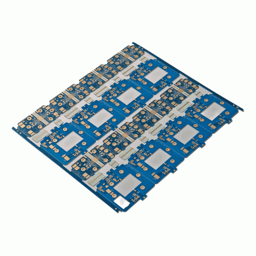
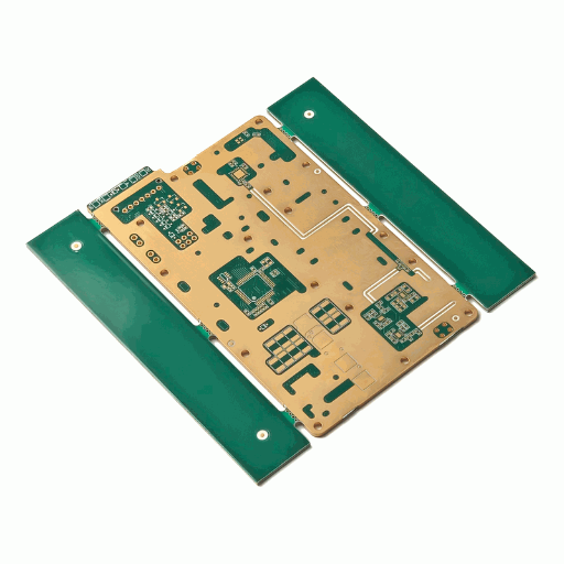
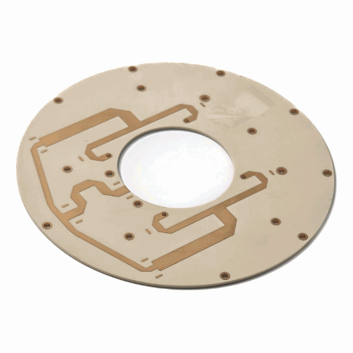
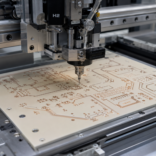
From ro4003c prototypes to 32-layer rt/duroid hybrid stack-ups, PCBark builds rogers pcbs that hold 5% impedance where FR-4 designs lose the signal. 16 years of EMS production, IPC Class 3 inspection, and material certificates on every shipment.
- Dk 2.2–10.2 Laminate range supported
- 0.050 mm Min. trace / spacing
- 100% E-test + AOI + TDR
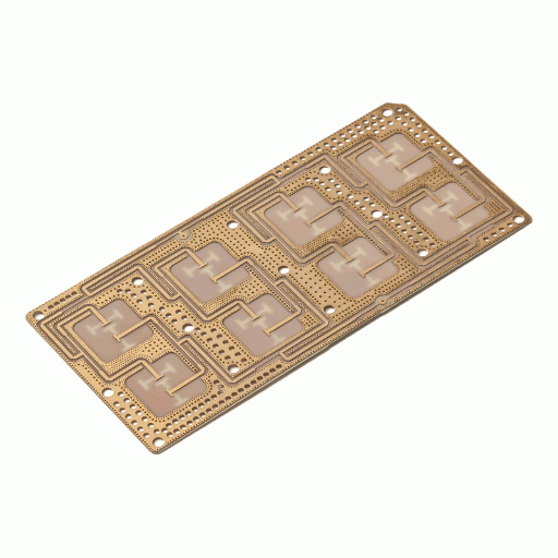
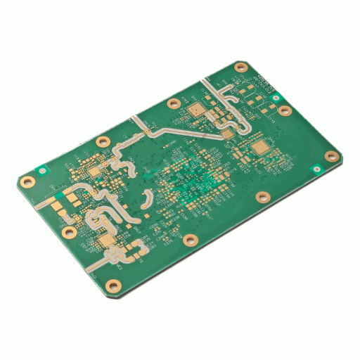
01 / 06
2–32
Layer count (Rogers & hybrid)
±5%
Controlled impedance (Best tier)
16 yrs
EMS production, 30+ countries
Why High-Frequency Designs Fail on FR-4 — and How Rogers Laminates Fix Signal Loss
A rogers pcb is a high-frequency circuit board built on Rogers Corporation laminates – hydrocarbon-ceramic and ptfe substrates engineered for tight dielectric control instead of the loose, lossy behavior of standard FR-4. That difference isn’t cosmetic. Above roughly 1-2 GHz, an FR-4 board with a dissipation factor near 0.020 bleeds signal energy as heat, and its dielectric constant drifts with frequency and temperature, so a 50 line no longer measures 50 at the antenna port.
Here’s the honest part most suppliers won’t tell you:
Rogers material isn’t always the right answer. For low- and mid-frequency work, FR-4 is perfectly adequate, and forcing every layer onto Rogers just burns budget. Industry guidance from the microwave Journal “ROG Blog” makes the same point – laminate selection is a frequency-and-loss-budget decision, not a default. PCBark engineers start by asking what your design actually needs, then route you to the right grade or a high-frequency PCB hybrid stack-up. That advice is where the next two sections come in.
PCBark Rogers PCB Manufacturing Capabilities
3-Tier Process Matrix
The fastest way to qualify a rogers pcb manufacturer is to read its real process window, not its adjectives. PCBark’s measured capability spans three build tiers – Standard production, Best (tightened) capability, and Maximum (advanced RF) capability. Every value is a shop-floor parameter, not a marketing claim.
Table 1, The Rogers PCB 3-Tier Capability Ladder
| Parameter | Standard | Best | Maximum |
|---|---|---|---|
| Material families | RO4003C, RO4350B | RO3003/3006/3010, RT/duroid 5880 | RO4835, RO4450F, TMM, custom |
| Layer count | 2–6 | 4–16 | 32 |
| Material build | All-Rogers single material | Rogers + FR-4 hybrid stack-up | Multi-material RF hybrid |
| Board thickness | 0.2–2.0 mm | 0.15–3.2 mm | 0.10–5.0 mm |
| Copper weight | 0.5–2 oz | 0.5–4 oz | 6 oz |
| Dielectric constant (Dk) | 3.38–3.66 | 2.2–10.2 | Project-based selection |
| Impedance tolerance | ±10% | ±8% | ±5% |
| Min. trace / spacing | 0.10 / 0.10 mm | 0.075 / 0.075 mm | 0.050 / 0.050 mm |
| Min. hole size | 0.25 mm | 0.20 mm | 0.10 mm |
| RF impedance structures | 50Ω, 75Ω | Single-ended, differential, CPW | Multi-impedance RF structures |
| Surface finish | ENIG, OSP | + Immersion Silver, HASL-LF | + ENEPIG, Hard Gold, custom |
| Max. finished board | 400 × 500 mm | 500 × 600 mm | 600 × 1200 mm |
| Testing | 100% E-test | + AOI, flying probe | + TDR impedance, RF evaluation |
MATERIALS BACKGROUND: Ultra-low-loss laminate chemistry for high-layer-count multilayer boards is documented in USPTO patent US9332637B2.
Engineering Note: Why Impedance Tolerance Is The Number That Matters
RF buyers on forums like r/PrintedCircuitBoard repeat one warning: controlled impedance is an option you must explicitly request, and the fab has to verify it – not just calculate a stack-up. PCBark closes that gap with TDR (Time-Domain Reflectometry) measurement on test coupons against your target 50 or 75 line, holding 5% at the Best/Maximum tier. The stack-up is calculated to IPC-TM-650 methods, then the finished board is measured, so what you specify is what ships.
“On Rogers builds we treat the impedance coupon as a pass/fail gate, not a courtesy. A 50Ω line that TDR-measures at 47Ω goes back, because at 28 GHz that 6% error is the difference between a clean eye and a failed EMC scan.”
PCBark RF Process Engineering Team
Choosing the Right Rogers Laminate — RO4003C, RO4350B, RT/duroid 5880 & RO3003 Selection Matrix
Most selection mistakes come from one myth: that all high-frequency laminates are interchangeable. They aren’t. Your grade choice sets the loss budget, the maximum usable frequency, the assembly process, and the material cost – and getting it wrong means either a failed RF margin or money spent on performance you never needed. Below, the matrix maps the four workhorse Rogers grades against the parameters that actually drive the decision, using published Rogers Corporation datasheet values.
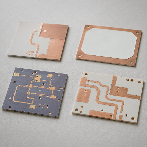
Rogers Grade-to-Application Selection Matrix
| Grade | Dk @10GHz | Df (tanδ) @10GHz | Max freq. | Cost vs FR-4 | Best-fit application |
|---|---|---|---|---|---|
| RO4003C | 3.38 ±0.05 | 0.0027 | 40 GHz | ~3–4× | 5G sub-6, Wi-Fi 6E, GNSS — best value workhorse |
| RO4350B | 3.48 ±0.05 | 0.0037 | 35 GHz | ~3.5–4.8× | Automotive radar, medical, lead-free / RoHS (UL 94 V-0) |
| RO3003 | 3.00 | 0.0013 | 77 GHz | ~6–7× | mmWave, 77 GHz ADAS radar |
| RT/duroid 5880 | 2.20 | 0.0009 | 110 GHz | ~8–10× | E-band backhaul, satellite, ultra-low-loss critical paths |
Grade chemistry reference: low-Dk, low-loss circuit-material formulations of this type are described in USPTO publication US20150030824A1.
Read the matrix as a decision path, not a ranking. RO4003C is the default for most sub-40 GHz work because it processes like FR-4 yet holds Df at 0.0027, which is why it’s the “go-to for prototyping RF layouts and even antennas” that hardware engineers keep recommending. Step up to RO4350B only when you need lead-free assembly or automotive thermal stability. Reserve RO3003 and RT/duroid 5880 for true mmWave, where every 0.1 dB of insertion loss counts and the 8–10× material premium is justified. If your design mixes a 6 GHz front end with digital control logic, you don’t need an all-Rogers board at all, which is exactly the cost lever the next section open up.
Buyer Advisory, Match the grade to the loss budget, not the price list
If you don’t knowwhether tora ro4003c ortoro4350b, question your reflow process; you’ll be fine with tin-lead soldering on RO4003C. For lead-free / RoHS production or any system that operates at automotive ranges- (-40°C to 125°C) – go with ro4350b. Send usthe frequency you’ve spec’ed, plus number oflayers, and impedance and get an honest assessment, whether that means a different Rogers PCB or a more cost-effective hybrid build, complete with a stack-up, within one business day.
Rogers vs FR-4 — Dk, Df, Loss & Cost Compared
The practical difference between Rogers and FR4 is a loss-budget decision. In any RF or microwave circuit board, the trade-off for moving from Rogers to FR4 is the compromise between high performance signal integrity and the sheer materials cost. FR4 may appear the winning value but for loss and dielectric stability at high frequency rogers prevails. Take a glance at the values below; they’re drawn from real world published material data, making trade-offs visually accessible.
Dk-Df Loss-Budget Comparison Grid
| Property | Standard FR-4 | Rogers RO4003C | Rogers RT/duroid 5880 |
|---|---|---|---|
| Dielectric constant (Dk) | ~4.3–4.5 (drifts) | 3.38 ±0.05 | 2.20 |
| Dissipation factor (Df) @10GHz | ~0.020 | 0.0027 | 0.0009 |
| Relative loss vs FR-4 | 1× (baseline) | ~7.4× lower | ~22× lower |
| Practical max frequency | <1–2 GHz | 40 GHz | 110 GHz |
| Raw material cost / area | ~$0.10–0.30 / in² | ~$0.80–1.50 / in² | Highest (PTFE) |
| Processing | Standard | FR-4-like (no PTFE handling) | Plasma prep, longer lamination |
Rogers PCB Applications — Antenna, Radar, 5G, Aerospace & Automotive
rogers pcb materials may cost a little more but that added expense is essential when your application mandatessignal integrityandthermal stabilityarecritical. A77 GHzradar module, satellite uplink – areas PCBark serves best – rely on the very stable Dks and ultra low loss you won’t find elsewhere.
Automotive Radar & ADAS
76–81 GHz radar modules for advanced driver-assistance systems (ADAS) on RO3003 or RT/duroid 5880, where copper surface roughness alone can add 25–45% insertion loss and cut detection range, so 9 µm foils and tight tolerance matter. RO4350B serves the lower-band ADAS sensors and IATF-grade builds.

5G & Telecom Infrastructure
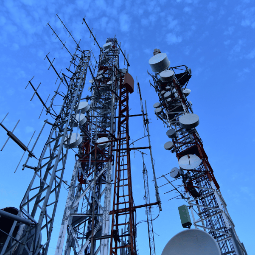
Base-station antennas, massive-MIMO arrays, and microwave point-to-point links on RO4003C, low dielectric loss keeps link budgets intact for the high-frequency RF circuit board at sub-6 GHz and mmWave.
Aerospace, Defense & Satellite
Antenna-grade laminates with low outgassing for spacecraft and satellite communication terminals, plus the vibration and thermal management headroom avionics demand. CTE stability keeps multilayer registration intact across extreme temperature swings.

Medical & Industrial RF
Diagnostic imaging, MRI front-ends, and high-frequency industrial sensing where RO4350B’s lead-free, dimensionally stable build supports regulated, long-life electronics.

×
![Enlarged Certification]()
Quality, Certifications & Reliability
For buyers who have yet to audit PCBark at our factory, certs and verified testing is the only way to truly discern data sheet claims from reality. Every Rogers build runs under multiple international quality systems, and every order come with full test documentation – no special request necessary.
ISO 9001:2015 Quality management
ISO 14001 Environmental
IPC-A-610 Class 2 / 3 acceptance
UL Listed materials/process
RoHS / REACH Compliance
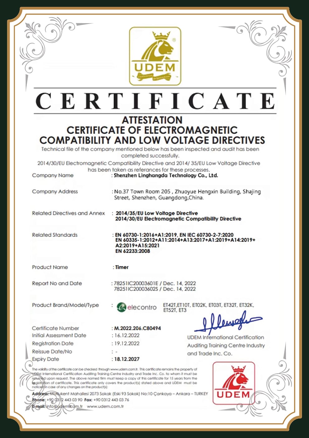
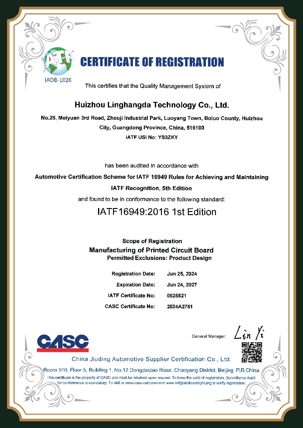
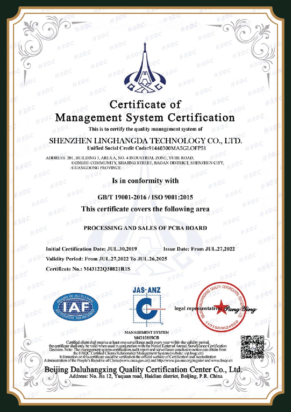
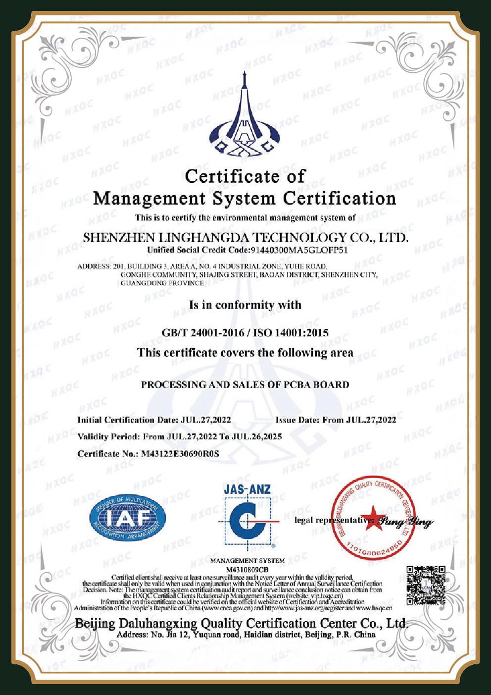
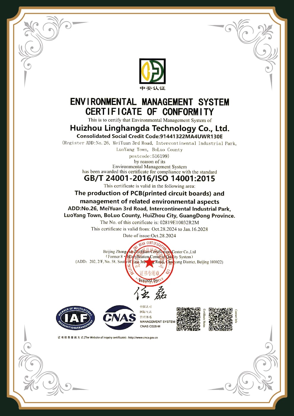
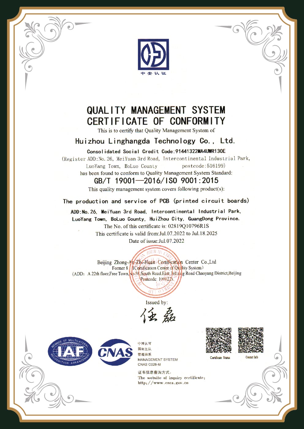
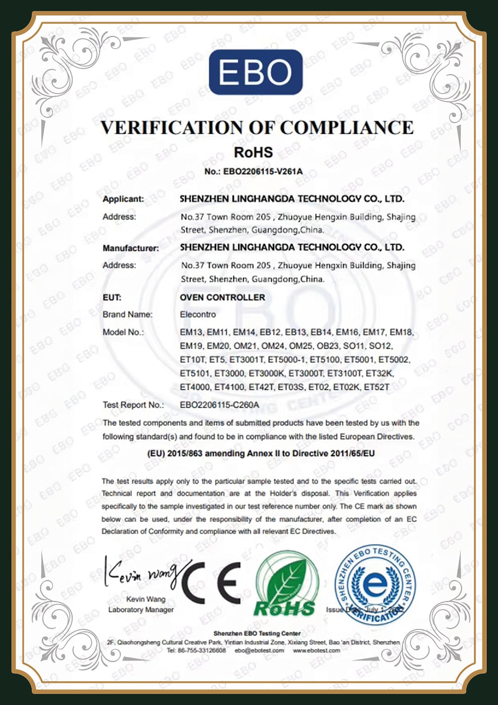
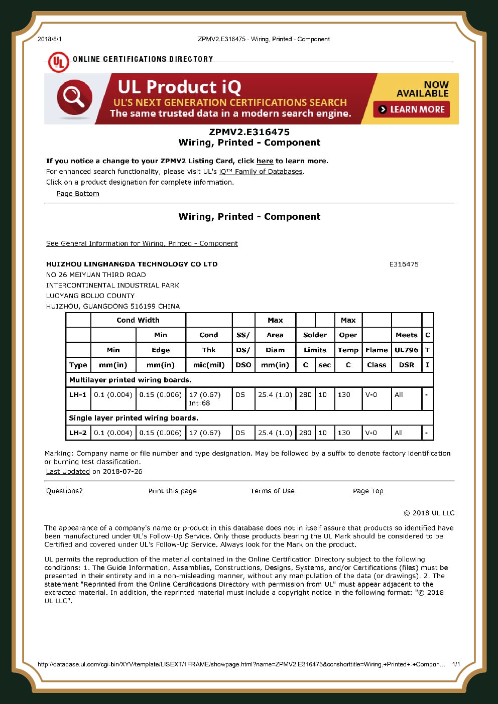
3 Steps Away From Legitimate Rogers And Dangerous Suppliers. PCBark Accounts For All Of Them.
Step 1. Authentication
Rogers requires the use of certificates of authenticity with traceable lot numbers with all shipments, so what you’re paying for is what you asked for-the genuine Rogers laminate you specified.
Step 2. Impedance Verification
Using TDR test coupons on every project and measuring what you ordered and having it meet IPC-4103 / IPC-6012 Class 3 specifications.
Step 3. Verification
Electrical testing on every unit built to IPC / AS9100 standards; AOI and x-ray on every assembles project, on all Rogers projects there’s a traceable supply line which helps keep everyone and everything in their designated places.
04
Rogers PCB Procurement Guide — Quoting, Lead Time & Mixed FR-4/Rogers Stack-ups
Buying rogers pcbs causes buyers to be duped the most costly way with over-pricing in regard to unit pricing alone that result from dishonest suppliers or omitting material authenticity. Use the information to avoid this pit fall with your new supplier relationships to quote fairly or accurately.
Pricing Factors Framework, what actually drives a Rogers PCB quote
When shopping for your next Rogers quote, you need more than a “ sticker price” or one generic quotation line item. “Stickers prices “ or price lists don’t make up the complete story. For an “ honest” quote you’ll want your Rogers supplier to respond with: the Rogers materials grade & Dk; Hybrid stack-up Rogers VS, Hybrid stack-up Rogers FR4 hybrid, Dk at signal layer; the layer count and board footprint sizes; Rogers impedance tolerance; a test coupon with your project ;Rogers surface finish options (Hard Gold vs ENEPIG), and the prototype to production run quantity you want quoted. Share those 6 (six) items and get a quotation that can withstand any budget!
[Get A Free, Detailed Quote Here ]When planning, remember there’s more to a PCB than the component.
The procurement for ptfe-based material, such as rt/duroid and RO3003, requires longer procurement cycles than that of RO4000 series products and should factor into prototype planning. While PCBark routinely manufactures orders as large as thousands, we’ve no minimum-order requirement and accommodate even single-piece orders with reasonable prototype pricing, so prototyping your multilayer stack-up projects becomes affordable. For designs incorporating both Rogers and FR-4, our engineers offer complimentary multilayer stack-up optimizations that balance differential pair phase-shift by matching the coefficients of thermal expansion between materials to prevent potential warpage. DFM is the precursor to an intelligent board plan; proactively review for DFM to avoid a costly redesign process after “ the quote is good.”
Rogers PCB Engineering & Design Tools
01
TOOL 01
Rogers Laminate Grade Selector
Answer three questions and get a starting Rogers grade with its real Dk/Df. Built from published Rogers Corporation datasheet values — confirm against your full stack-up with our engineers.
02
TOOL 02
Microstrip Trace-Width Estimator (Rogers)
Estimate the microstrip trace width for a target characteristic impedance on a Rogers substrate, using the IPC-2141 microstrip model. A first-pass number to size your layout — PCBark verifies the final value with TDR on test coupons.
03
TOOL 03
Hybrid FR-4/Rogers Stack-up Cost Saver
Most designs do not need every layer on Rogers. Put Rogers only on the RF layers and FR-4 on digital/power layers, and estimate the material-cost saving versus an all-Rogers build.
Frequently Asked Questions — Rogers PCB
FR-4 is woven glass plus epoxy with a dissipation factor near 0.020 and a Dk that drifts; Rogers laminates are ceramic-filled hydrocarbon or PTFE with Df as low as 0.0009 and a Dk held to ±0.05. In practice, FR-4 suits designs below ~1–2 GHz, while Rogers is built for RF, microwave, and mmWave where loss and impedance stability decide whether the circuit works.
Both are RO4000 hydrocarbon-ceramic laminates. RO4003C has lower loss (Df 0.0027 vs 0.0037) at slightly lower cost and is not UL 94 V-0 rated; RO4350B is lead-free / RoHS compatible, UL 94 V-0 rated, and more thermally stable — the better fit for automotive and medical builds.
The right grade depends on your frequency and loss budget. RO4003C covers most sub-40 GHz work and is the usual prototyping default; RO3003 and RT/duroid 5880 (Df 0.0009, usable to 110 GHz) are reserved for 77 GHz radar and mmWave links where minimum insertion loss is critical.
Yes — when it is documented. PCBark ships a Rogers Corporation certificate of conformance with lot traceability so the laminate is verified genuine, and confirms controlled impedance with TDR measurement on test coupons rather than calculation alone. Ask any supplier for both; the credible ones provide them.
No. If only part of your design runs at high frequency, a hybrid stack-up — Rogers on the RF layers, FR-4 on digital and power layers — typically cuts material cost 30–40% with minimal RF impact. We will tell you when an all-Rogers build is unnecessary.
Controlled impedance means specific traces are built and tested to hit a target value (commonly 50Ω or 75Ω). The stack-up is calculated, then the finished board is measured with TDR on coupons. PCBark holds ±5% at the Best/Maximum tier and reports the measured result.
Yes. Rogers laminates have low moisture absorption (around 0.04–0.06%), and selected grades carry low-outgassing approval for spacecraft. That dimensional stability is why they appear in avionics, satellite terminals, and radar exposed to vibration, vacuum, and wide temperature swings — environments where a standard FR-4 board would absorb moisture and drift out of spec.
PCBark builds 2–6 layers at the Standard tier and up to 32 layers at the Maximum tier. Controlled-impedance tolerance tightens from ±10% (Standard) to ±5% (Maximum), trace and space reach down to 0.050 mm, and the Dk window spans 2.2 to 10.2 across the full Rogers range — single-material or FR-4 hybrid.
![16-24 Layer PCB: Stackup, Lamination & Design Guide [2026]](https://pcbark.com/wp-content/uploads/2026/07/16-24-layer-pcb-guide-featured-2-150x150.png)


