
Get in touch with PCBark Company

[ SYS-01 ] BGA ASSEMBLY · SMT · DFM
- IATF 16949 CERTIFIED
- ISO 9001
- ISO 14001
- CE
- RoHS
- UL
BGA Assembly Service
Fine-Pitch Placement with Dual X-Ray QC — From Prototype to Production
- 0.3mmMin Pitch
- ±0.025mmAccuracy
- 100%X-Ray
- 9MPlacements/Day
- 24hPrototype
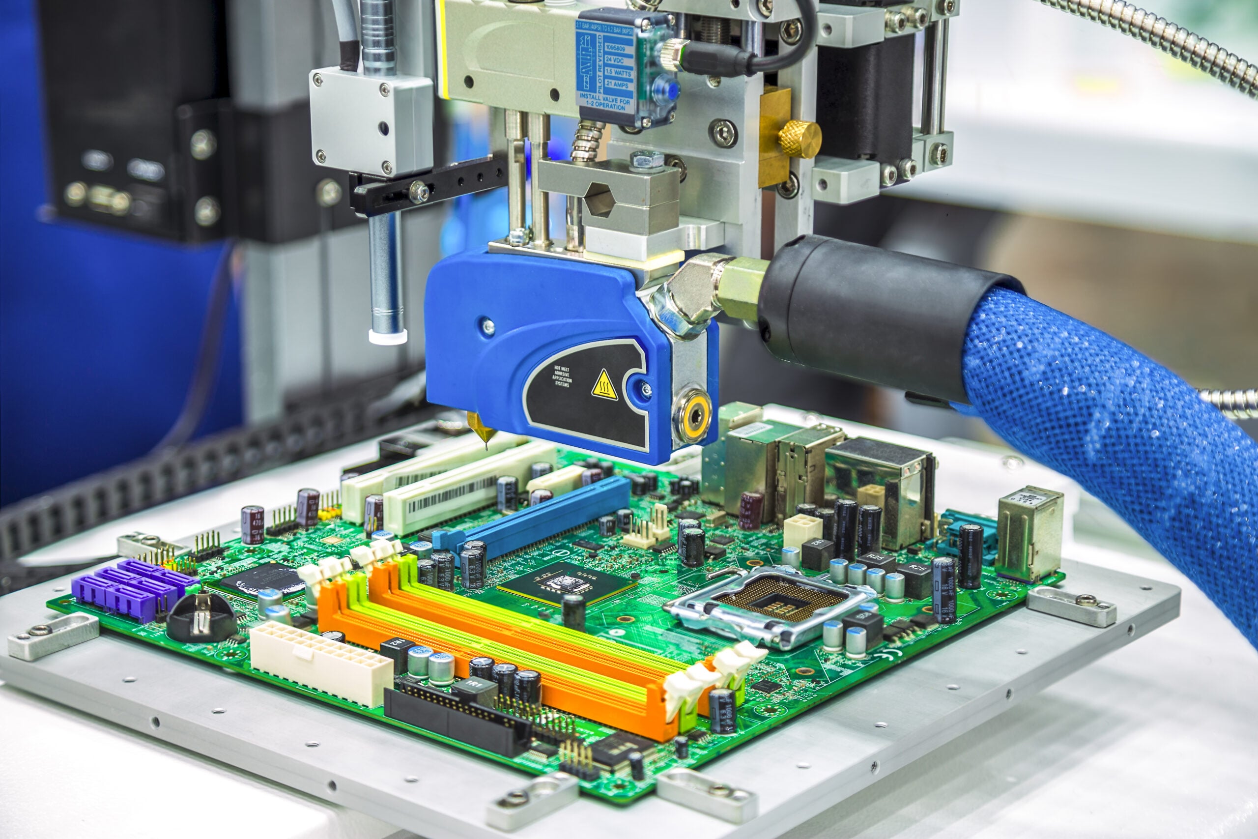 LINE-01 · SMT PLACEMENT
 QC-02 · DUAL X-RAY
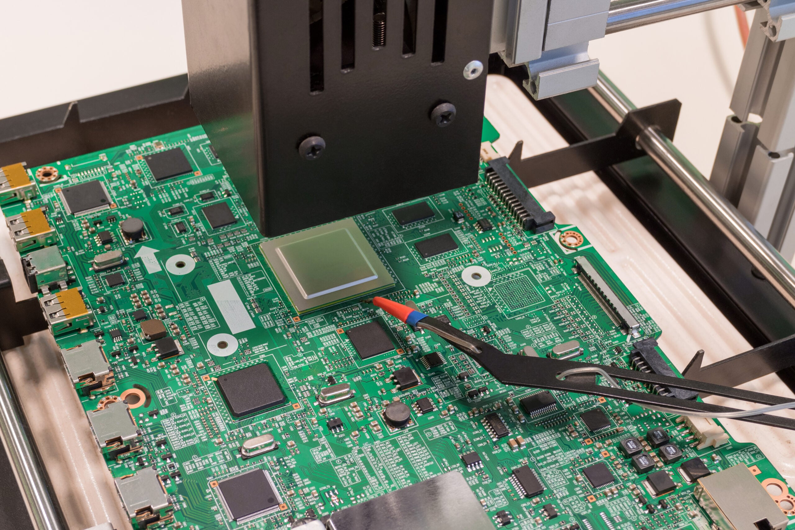 SYS-03 · PRODUCTION
±0.025mmPlacement Accuracy
D-019,000,000Placements / Day
D-028SMT Lines
D-030.3mmMin BGA Pitch
D-04100%X-Ray Coverage
D-051–15Business Days
[SYS-01] PCB Assembly
What Is BGA Assembly?
BGA assembly is the manufacturing process of soldering Ball Grid Array packages onto a printed circuit board (PCB). Each BGA component carries an array of solder balls on its underside rather than exposed leads along the edges. Because the joints sit hidden beneath the package, BGA assembly demands precise thermal profile control and mandatory X-ray inspection — standard optical inspection cannot see the solder joints at all.
PCBark’s PCB assembly service covers the full BGA workflow: DFM review, solder paste printing, Yamaha YSM20R pick-and-place, controlled reflow, AOI, 100% dual X-ray inspection, and in-house BGA rework using the Metcal ZM-R5830 station. Every order ships with traceable inspection data.
Professional BGA assembly is a quality prerequisite — not a cost preference. A 90%+ board failure rate from hidden BGA defects is the direct cost of an undertreated assembly process. The question is not whether to use professional BGA assembly, but which factory has the process controls to make every joint reliable.
Start Your BGA Assembly DFM Review
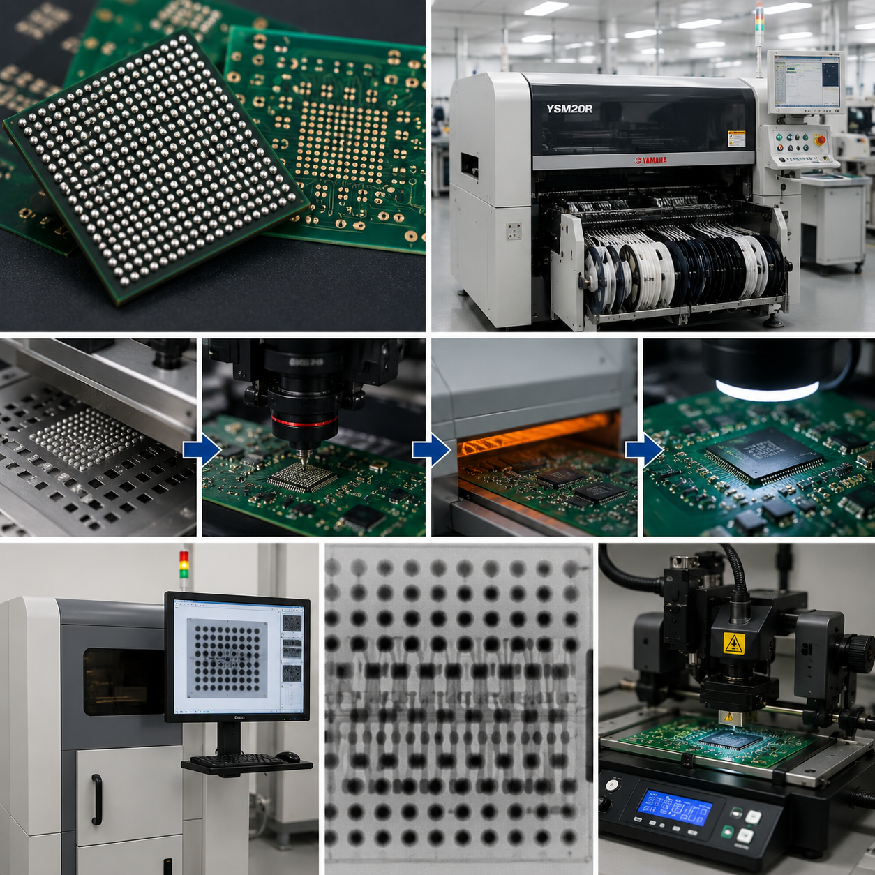 X-RAY · AOI
100%Dual X-Ray
08Process Steps
PCBark BGA Assembly Covers
- 01DFM Review
- 02Solder Paste Print
- 03Yamaha YSM20R Placement
- 04Reflow Soldering
- 05AOI
- 06Dual X-Ray Inspection
- 07Rework (if needed)
- 08Final Test
9 BGA Package Types Supported
PCBark supports all mainstream BGA package families — including fine-pitch WLCSP at 0.35mm minimum pitch. Package type, ball count, pitch, and substrate each dictate thermal profile, void requirements, and process approach for every build.
Request a BGA Assembly Assessment
PATENT DATA
US11916003B2 — Varied-ball BGA yield improvement (2024)
CAP-MATRIX / MIN PITCH
0.35mm WLCSP
PROCESS CAPABILITIES
- FAMILIES9 BGA package types
- MAX BALLS1,000+ (FCBGA)
- FORMATSWLCSP · FCBGA · PoP · LGA
[SPEC-02] Package Matrix
BGA assemblies in advanced formats such as flip chip CSP, system-in-package (SiP), or embedded die may require project-specific process development. Contact our engineering team for assessment.
BGA Assembly Capabilities
Equipment specifications and actual production metrics — no estimations. Rapid prototype quantities begin within 24 hours and scale to full production volume on the same lines.
Reliability benchmark: NASA Electronic Parts & Packaging Program (NEPP) — BGA thermal-cycle reliability research.
±0.025mm
Placement Accuracy
(Yamaha YSM20R, 3σ)
(Yamaha YSM20R, 3σ)
0.3mm
Minimum BGA Pitch
(WLCSP: 0.35mm)
(WLCSP: 0.35mm)
Dual X-Ray
100% BGA Coverage
MK-2001 + XC-3001
MK-2001 + XC-3001
24h
Prototype Turnaround
(1–10 pcs expedited)
(1–10 pcs expedited)
BGA Assembly Process — DFM to Final Test
PCBark’s BGA assembly process runs through eight interdependent stages. Each gate must pass before the next begins.
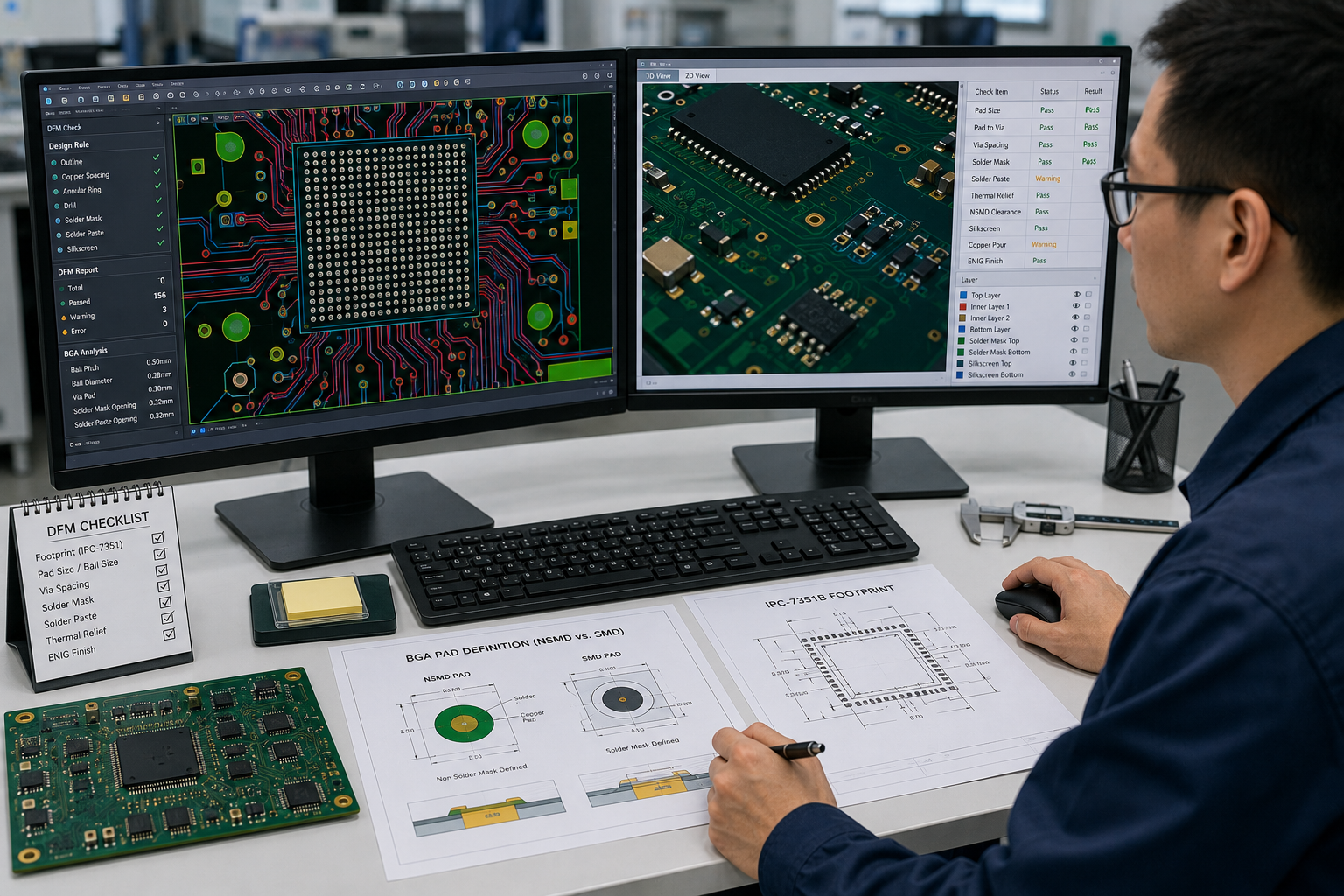
STAGE-01
1. DFM Review
Engineers inspect all pad designs against IPC-7351 footprints, reviewing NSMD vs. SMD pad definitions and ENIG finish suitability. Mismatches in pad/ball size, via spacing, or thermal pour conflicts are flagged before fabrication begins.
STAGE-02
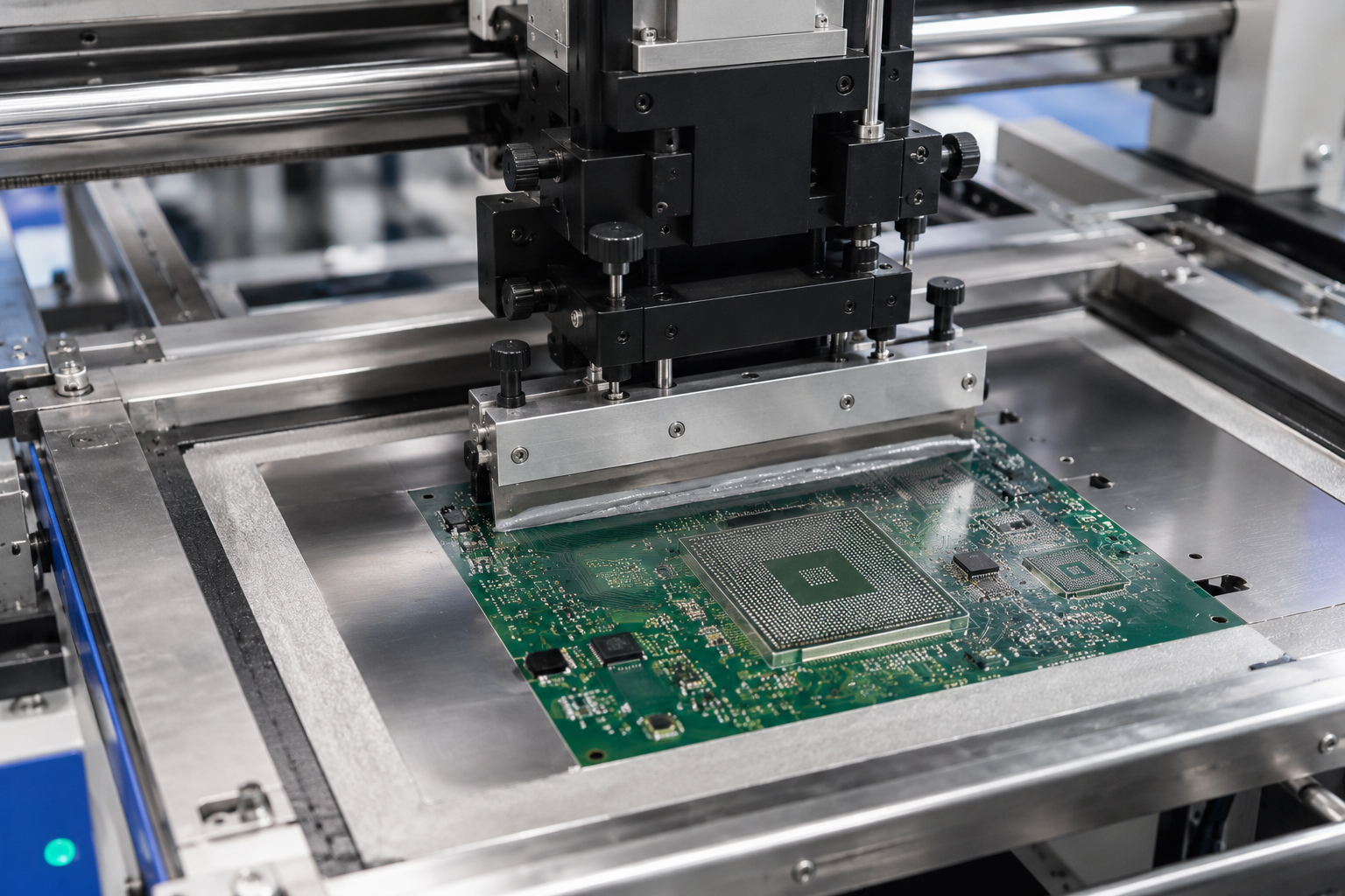
2. Solder Paste Print
Laser-cut stainless steel stencils deposit solder paste onto BGA pads with ±10% volume control. Precise paste volume prevents bridging and head-in-pillow defects before any component is placed.

STAGE-03
3. Pick-and-Place (Yamaha YSM20R)
The YSM20R places each BGA component within ±0.025mm accuracy. Vision-guided alignment compensates for board warpage in real time — critical for fine-pitch WLCSP and FCBGA packages.
STAGE-04
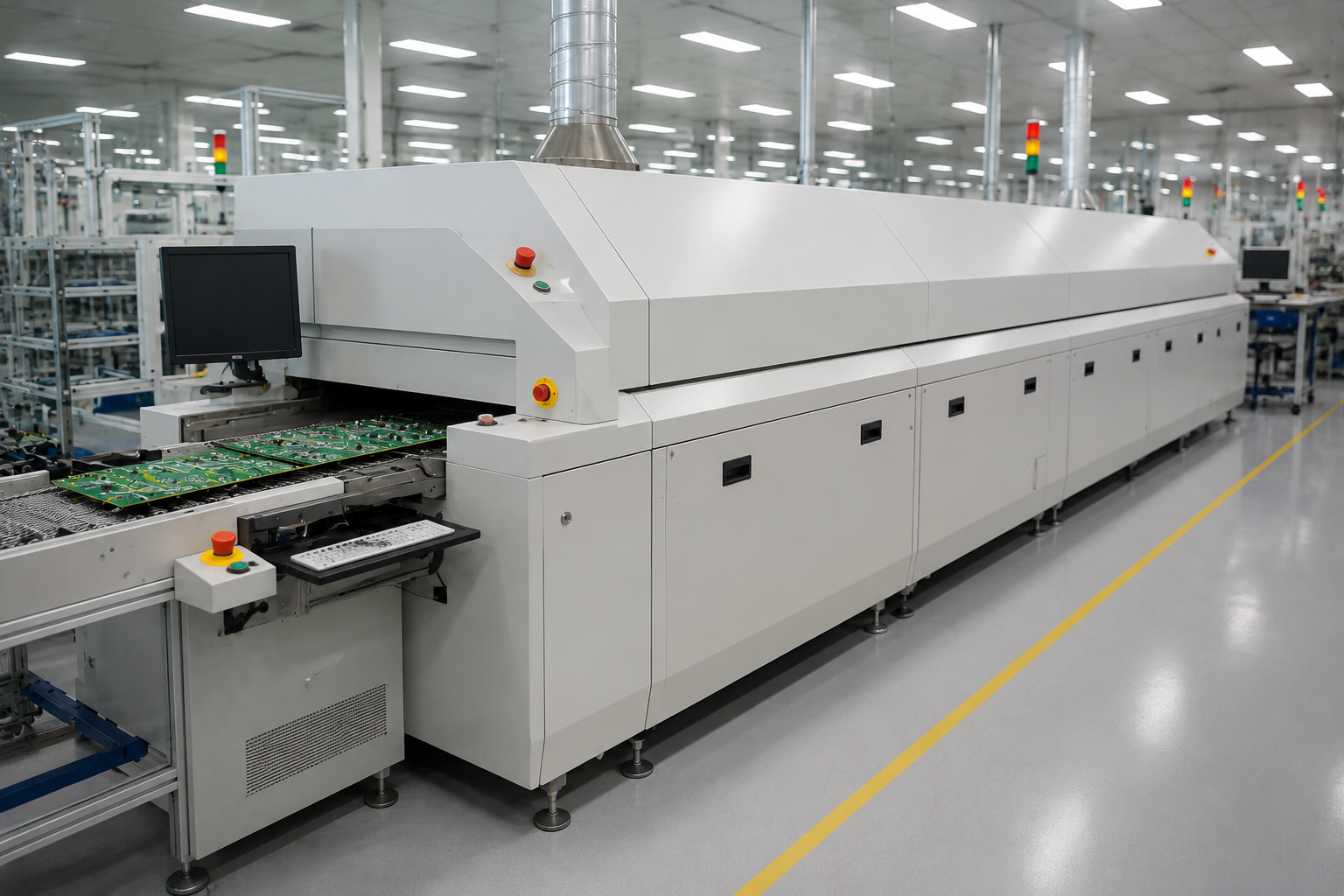
4. Reflow Soldering
A 10-zone Wuxi JTE-1200D reflow oven executes a controlled thermal profile: 1–3°C/s ramp-up, 150–180°C soak, 235–245°C peak (SAC305), and controlled cool-down. CBGA and PBGA packages each require distinct profile parameters.

STAGE-05
5. AOI (Automated Optical Inspection)
The Jiaguang VCTA-D820 dual-track AOI system inspects surface conditions: placement, orientation, and visible solder quality. Note: AOI cannot inspect BGA solder joints hidden beneath the package body — that role belongs exclusively to X-ray.
STAGE-06
6. Dual X-Ray Inspection
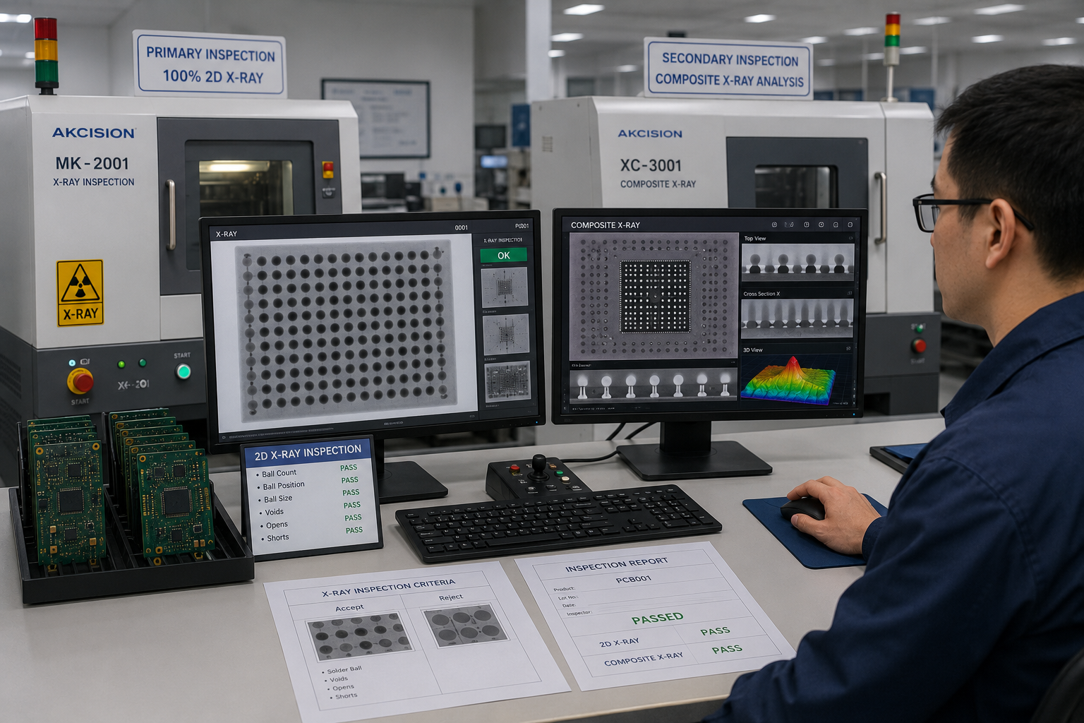
Every BGA assembly passes 100% through the Akcision MK-2001 2D X-ray. Fine-pitch, multi-BGA, or 6-layer-plus boards also receive XC-3001 composite X-ray analysis as a second inspection tier.
STAGE-07
7. Pass / Rework Decision
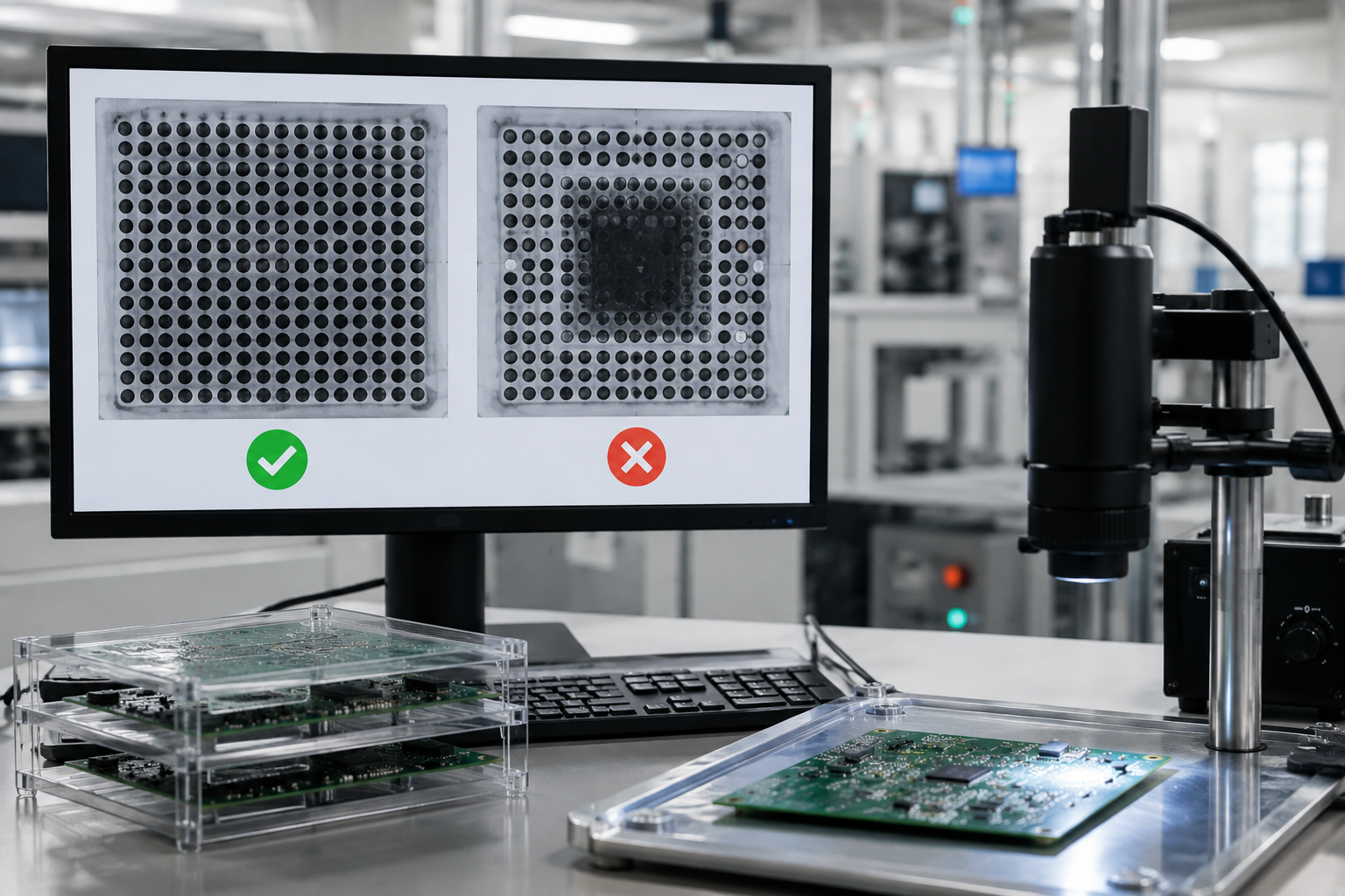
X-ray images are reviewed against IPC-7095C and JEDEC void tolerances. PCBark’s internal limit is <20% void area — stricter than IPC’s 25% evaluation threshold. Failing boards proceed to BGA rework; passing assemblies continue to final test.
STAGE-08
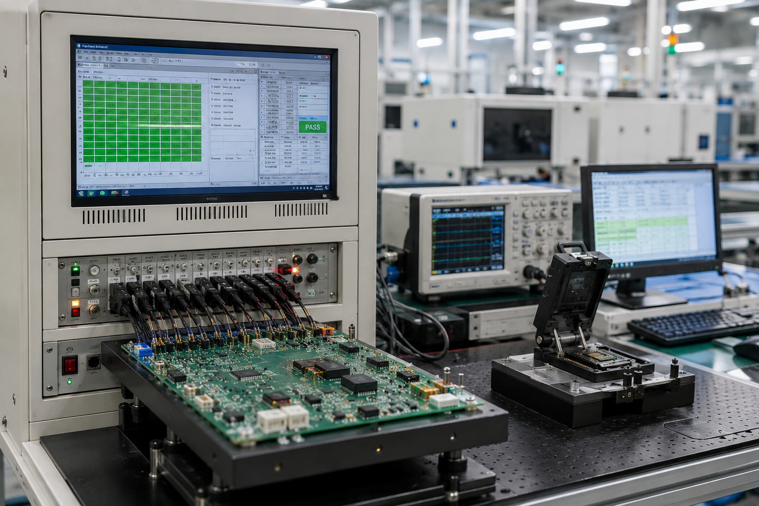
8. Final Testing
Order requirements determine the test suite: ICT for electrical continuity, flying probe for low-volume builds, burn-in for high-reliability applications, or functional test using customer-supplied fixtures.
The PCBark Dual X-Ray Protocol
PCBark operates two purpose-built Akcision X-ray systems — the only EMS in the competitive field to disclose both machine types and the decision logic for when each is applied. Neither machine is a repurposed medical or industrial imaging system.
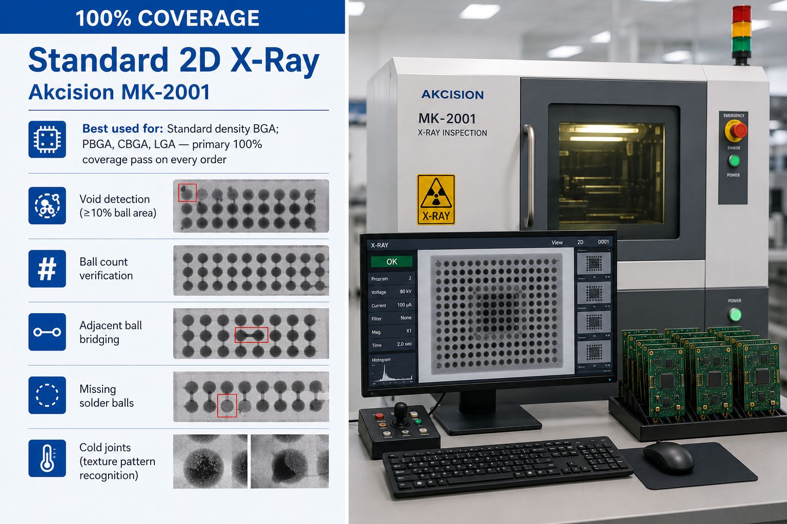
Standard 2D X-Ray
Akcision MK-2001
Best used for: Standard density BGA; PBGA, CBGA, LGA — primary 100% coverage pass on every order
- Void detection (≥10% ball area)
- Ball count verification
- Adjacent ball bridging
- Missing solder balls
- Cold joints (texture pattern recognition)

Composite X-Ray
Akcision XC-3001
Best used for: Fine-pitch BGA (µBGA, WLCSP, FCBGA); ≥6-layer boards; PoP assemblies; high-density complex builds
- Fine-pitch bridging (≤0.5mm pitch)
- Multi-layer void analysis
- Package warpage standoff detection
- Misalignment at ≤0.1mm resolution
- Alloy composition (density contrast)
XC-3001 Assignment Logic
Every BGA board runs through the MK-2001 (guaranteeing 100% coverage on all BGA assemblies). A board also receives XC-3001 composite inspection when any of the following apply: BGA pitch is ≤0.5mm; 3 or more BGA devices on one PCB; 6 or more copper layers; or PoP stacked assemblies.
AOI Cannot Inspect BGA Solder Joints
AOI checks visible surface conditions — up to ~90% surface defect coverage — but cannot reach solder joints hidden beneath the BGA package body. Any EMS describing their BGA inspection as “AOI only” is describing a process that physically cannot inspect the most critical joint on the board. Without X-ray, there is no BGA quality process, regardless of marketing language. PCBark’s internal void acceptance limit is <20% — stricter than IPC-7095C’s 25% evaluation threshold. Boards outside this spec are flagged for disposition review, not approved.
| Defect Type | Severity | AOI Detectable | MK-2001 (2D X-ray) | XC-3001 (Composite) | Required Action |
|---|---|---|---|---|---|
| Solder void ≥25% ball area | High (IPC reject) | ✗ No | ✔ Yes | ✔ Yes | Rework |
| Solder void 10–25% ball area | Medium (evaluation) | ✗ No | Partial (size-dep) | ✔ Yes | Disposition per IPC-7095C |
| Adjacent ball bridging | Critical (short circuit) | ✗ No | ✔ Yes | ✔ Yes | Rework |
| Missing solder ball | Critical (open joint) | ✗ No | ✔ Yes | ✔ Yes | Rework / Reballing |
| Ball misalignment ≤0.1mm offset | Medium | ✗ No | ✗ No (below res) | ✔ Yes | Monitor / Rework |
| Head-in-pillow (insufficient solder) | High (intermittent) | ✗ No | Partial | ✔ Yes | Rework |
| Cold joint (crystalline texture) | High (reliability risk) | ✗ No | ✔ Yes (texture) | ✔ Yes | Rework |
| Package warpage (standoff below min) | High (opens under stress) | ✗ No | ✗ No (2D proj) | ✔ Yes (height est) | Rework / Replace |
| Incorrect alloy composition | Medium (RoHS risk) | ✗ No | ✗ No | ✔ Yes (density) | Disposition review |
Quality Certifications & Inspection Suite
PCBark’s quality management systems encompass the entire assembly lifecycle. Inspection alone cannot fix a weak process — quality begins at DFM review and runs through every stage.
❮







❯
-
[CERT-01]
ISO 9001:2015
Quality Management System — documented procedures, process controls, corrective action, and continuous improvement programs.
-
[CERT-02]
ISO 14001:2015
Environmental Management — RoHS-compliant manufacturing; controlled disposal of all solder and chemical waste.
-
[CERT-03]
IATF 16949:2016
Global automotive QMS — covers APQP, FMEA, and control plan requirements. Currently the only top-10 result for “BGA assembly service” with this certification.
-
[CERT-04]
CE Marking
Conformity mark for products sold within the European Economic Area (EEA).
-
[CERT-05]
RoHS
Restriction of Hazardous Substances — lead-free solder process complying with Directive 2011/65/EU.
-
[CERT-06]
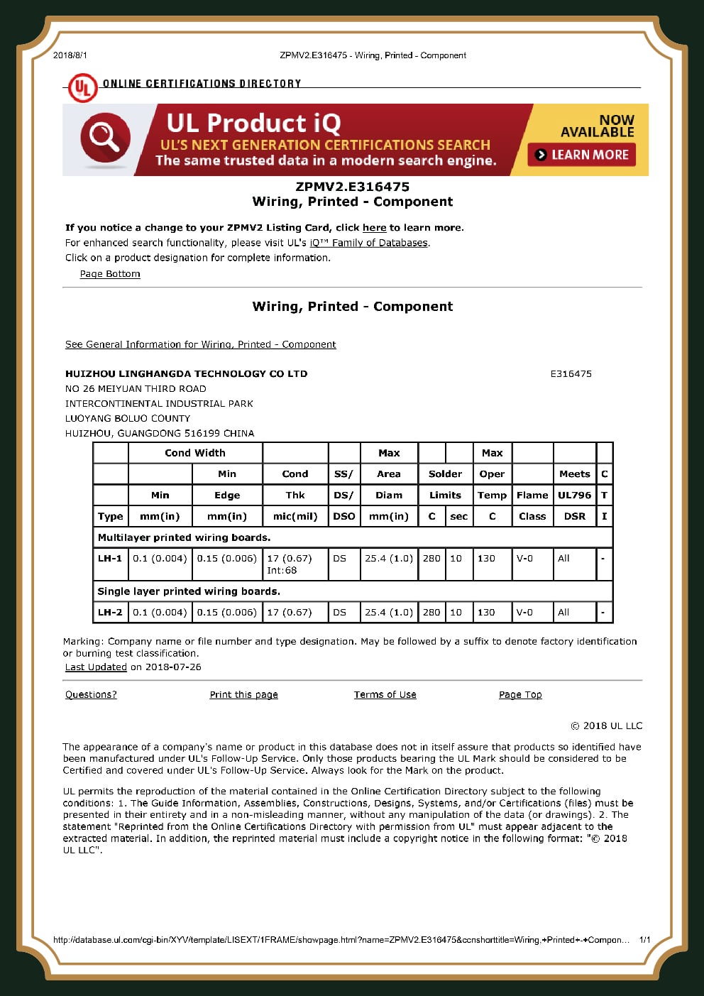
UL Certification
Underwriters Laboratories recognition for applicable manufacturing processes.
[DATA_LOG] Certification standards: ISO 9001:2015; ISO 14001:2015.
[SYS-PIPE] Layered Inspection Pipeline
-
[STAGE-01]
1. SPI — Solder Paste Inspection
Verifies solder volume and pad alignment before component placement. Addresses over 60% of downstream defects originating at the print stage.
-
[STAGE-02]
2. AOI — Automated Optical Inspection
Jiaguang VCTA-D820 dual-track line scan detects tombstoning, leaded bridging, polarity errors, and component skew. Cannot evaluate BGA solder joint quality.
-
[STAGE-03]
3. Dual X-Ray — BGA Joint Inspection (100%)
MK-2001 + XC-3001 inspect all BGA void, bridge, missing ball, and fine-pitch defects per the Dual X-Ray Protocol above.
-
[STAGE-04]
4. ICT / Flying Probe
Bed-of-nails or flying probe tests shorts, resistor/capacitor values, and diode orientation. Flying probe ideal for lower volumes without custom fixture tooling.
-
[STAGE-05]
5. Burn-In — Stress Testing
Prolonged stress under elevated temperature and electrical conditions, used for aerospace, defence, and industrial high-reliability applications.
-
[STAGE-06]
6. FCT — Functional Board Validation
Validates overall board-level operation using customer-supplied test fixtures to simulate real-world operating conditions.
[SPEC_REQ] IPC-A-610 Class II by default. Class III (military/aerospace) available on request — specify at quote stage.
Why PCBark for BGA Assembly
When evaluating BGA assembly partners, buyers consider five critical dimensions. Here is how PCBark performs across each — with equipment specifications and certifications behind every claim.
PCBark handles BGA as part of its broader circuit card assembly service — including SMT, THT, and mixed-technology builds, all on the same production lines.

[SYS-01] DEPTH
Dual X-Ray Depth
Two purpose-built Akcision X-ray systems: MK-2001 runs 100% of BGA boards; XC-3001 adds a second inspection tier for complex assemblies. No competitor in this space operates two X-ray systems.

[SPEC-02] ACCURACY
Fine-Pitch Accuracy (±0.025mm)
Five Yamaha YSM20R machines deliver ±0.025mm placement accuracy, supporting BGA pitches down to 0.35mm WLCSP. High-mix BGA assembly exceeds 20,000 BGAs/hour with no process bottlenecks.
[NODE-03] IN-HOUSE
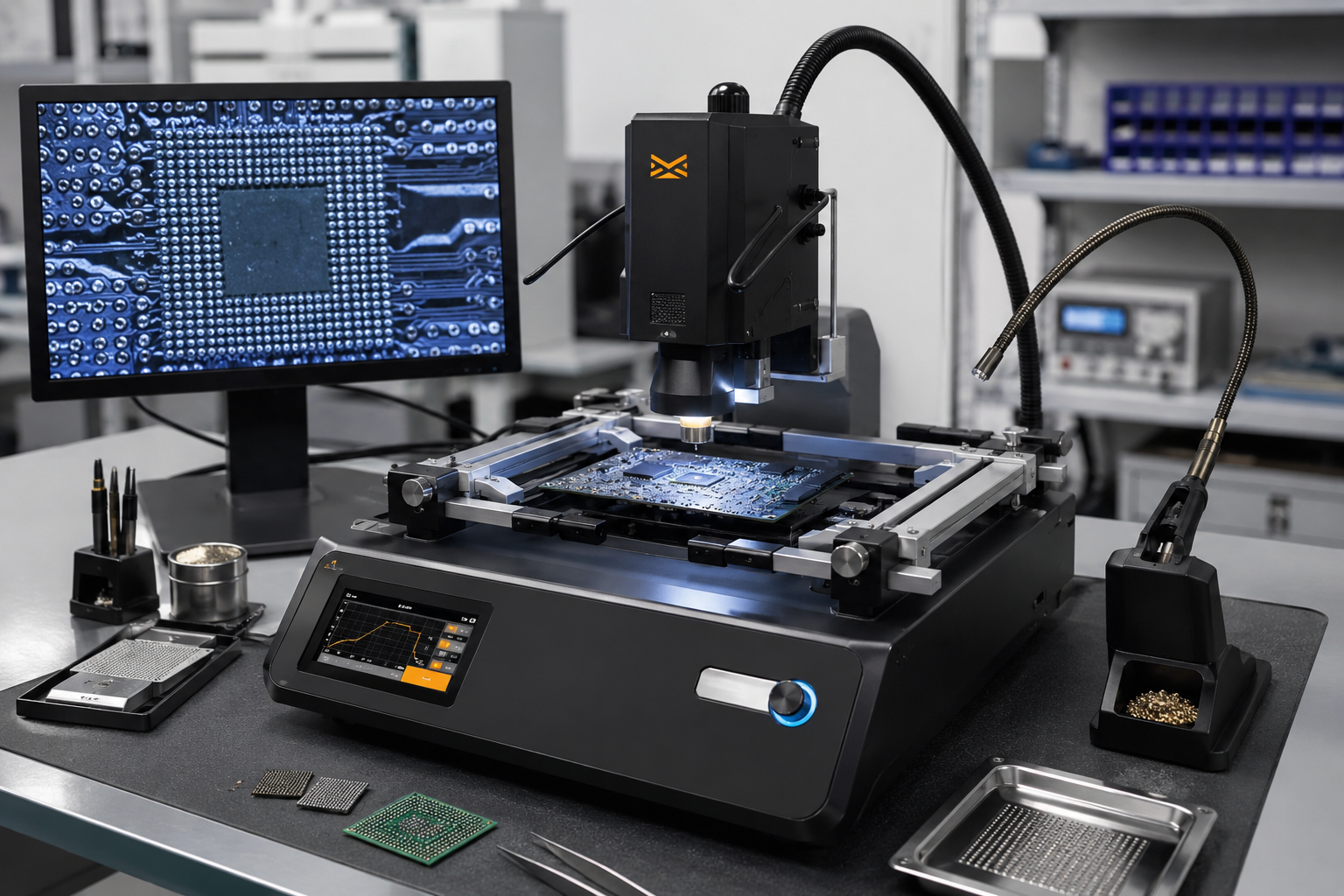
In-House BGA Rework (ZM-R5830)
The Metcal ZM-R5830 station handles on-site BGA removal, pad redress, reballing, and reflow. No outsourcing, no chain-of-custody gaps, no communication delays between your design team and rework technicians.

[CERT-04] STANDARD
IATF 16949 Automotive Grade
PCBark’s IATF 16949:2016 certification covers APQP, FMEA, and control plan requirements — the strictest global automotive quality standard. Currently the only top-10 result for “BGA assembly service” with this certification.

[CAP-05] SCALE
Production Capacity (9M/day)
8 SMT lines and 9,000,000 component placements per day on boards up to 680 × 550mm. The same factory that builds your prototypes handles your production ramp — no factory switch, no quality reset.
Industries Served
Aerospace & Defense
Explore aerospace capabilities →Medical Devices
diagnostic equipment, patient monitoring
Telecommunications
base station ICs, networking ASICs
Automotive Electronics
ADAS modules, ECU, power management BGA
Industrial Control
PLC, motion controller, power electronics
Consumer Electronics
high-density consumer product platforms
Networking Infrastructure
switch/router processor BGA assemblies
Test & Measurement
instrumentation, data acquisition systems
Ready to Start a BGA Assembly Project?
Upload your Gerbers and BOM, and PCBark’s engineering team will provide a detailed quote within 24 business hours, including Design for Manufacture (DFM) feedback.
BGA Assembly Engineering Calculators
Deploy our proprietary engineering models to evaluate your BGA assembly compliance, estimate hidden defect costs, and select the optimal package parameters before entering the manufacturing phase. These tools are built upon IPC-7095C standards and PCBark’s extensive dual X-Ray inspection data.
Void Acceptance Calculator
Calculate IPC-7095C compliant voiding thresholds for your specific BGA package size and pitch. Ensure your joints pass mission-critical reliability standards.
Launch Calculator →
Hidden Defect Cost Estimator
Quantify the financial impact of insufficient X-ray coverage and internal BGA joint failures on your production yield and field recall expenses.
Estimate Costs →
BGA Package Selector
Evaluate PBGA, FCBGA, WLCSP, and other formats against your thermal, pitch, and layer-count requirements to find the optimal footprint.
Select Package →
Supplier Qualification Scorecard
A rigorous evaluation matrix to audit EMS providers on their specific BGA placement, X-ray inspection, and dedicated rework capabilities.
Start Evaluation →
BGA Assembly & Technical Capabilities FAQ
Standards Basis: US6489557B2 (Micro BGA) | IPC-7095C | J-STD-001
PCBark features specialized manufacturing lines capable of ultra-fine pitch placement down to a minimum BGA ball pitch of 0.35 mm for micro-BGA architectures. For production viability, our automated optical and pick-and-place matrices leverage custom nozzle configurations to ensure pristine alignment, staying fully compliant with the geometric scaling constraints dictated by patent US6489557B2.
Yes, we operate independent, designated thermal reflow profiling lines for both lead-free (SAC305) and traditional leaded (Sn63Pb37) components. This separation eliminates any risk of cross-contamination and ensures precise alloy-specific thermal management according to J-STD-001 soldering requirements.
To generate an accurate and streamlined assembly quote, please provide your Gerber or ODB++ array files, a complete Bill of Materials (BOM) including manufacturer part numbers, an ASCII-formatted Centroid coordinate file (Pick and Place file) indicating rotation parameters, and clearly annotated assembly drawings.
Yes, PCBark is equipped with high-precision surface mount machinery that supports vertical device layering and advanced dip-fluxing methods. This allows for reliable Package-on-Package (PoP) assemblies, combining processor logic and memory configurations within compact footprints while ensuring perfect solder-joint coplanarity.
X-ray inspection is mandatory and performed on 100% of the assembled BGA packages on our boards. Our automated 3D X-ray systems screen specifically for solder voiding ratios, bridges, head-in-pillow effects, and concentric misalignments, matching the baseline benchmarks defined within the IPC-7095C process control standard.
Yes, we provide IPC-A-610 Class 3 inspection for high-reliability medical, aerospace, and critical military hardware. This service involves heightened visual verification metrics, meticulous process logging, and structural cross-checks to ensure continuous operation in severe or harsh environmental conditions.
Our typical turn-around window for prototype BGA assembly scales from 24 to 48 hours for expedited quick-turn runs. Standard low-to-mid volume production cycles generally require 5 to 7 business days following the complete arrival and verification of all kit components and bare substrates.
Yes, we have high-end, automated split-vision hot-air rework stations to safely remove, clean, re-ball, and replace faulted BGA structures. Thermal profiling is localized during rework cycles to shield adjacent components from heat damage, strictly upholding the post-rework integrity baselines of IPC-7095C.
We highly recommend Electroless Nickel Immersion Gold (ENIG) or ENEPIG finishes for fine-pitch BGA arrays. ENIG yields an exceptionally flat surface topography that prevents component skew or uneven ball height issues common with HASL, while our strict chemistry monitors avoid the risks of “black pad” defects.
PCBark’s DFM review for fine pitch BGA covers pad geometry versus IPC-7351 footprint requirements (NSMD preferred for fine-pitch applications), solder mask registration tolerances, the impact of via-in-pad on BGA escape routing capabilities, the impact of ball pitch on stencil aperture sizes, ENIG finish suitability and thermal relief design at BGAs.
Deliverable: All reviews are delivered in a written report and is at no additional cost to the customer for the initial review.

![16-24 Layer PCB: Stackup, Lamination & Design Guide [2026]](https://pcbark.com/wp-content/uploads/2026/07/16-24-layer-pcb-guide-featured-2-150x150.png)


