
Get in touch with PCBark Company

Industrial Control PCB & PCBA Solutions for Automation Equipment
Rugged boards for PLCs, motor drives, power supplies and sensors – built to IPC Class 2 or Class 3, fully tested and traceable, by a turnkey EMS partner with 16+ years on the line.
Request a Quote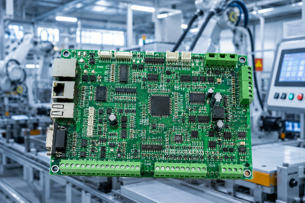
8
SMT lines · 9M placements/day
-40 to +85°C
Industrial temp range · high-Tg FR-4
IPC 2/3
Class to your application, not by default
1–15 days
Prototype to volume turn time
6
Test methods: X-ray · AOI · ICT · flying probe · burn-in · functional
500,000 m²
Annual production capacity · 16+ yrs
Why Industrial Control Boards Fail in the Field, and How to Prevent It
FIELD FAILURE DATA
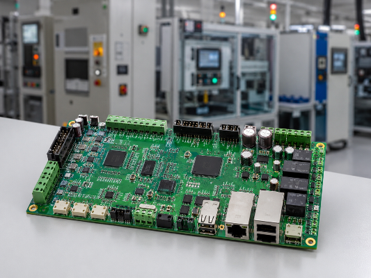
An industrial control PCB is the printed circuit board at the heart of a PLC controller, motor drive, power supply or sensor node – and when it fails on a running line, the board is the cheapest thing you lose. Heat, vibration, humidity and electrical noise are the four stresses that quietly degrade control electronics in a plant. Most field failures trace back to choices made before the first board was ever fabricated.
The real problem isn’t the board price — it’s the consequence of a stoppage. Industry analyses of 2024 plant data put the average cost of unplanned manufacturing downtime near $260,000 per hour. A control board that costs tens of dollars can idle a line that bleeds thousands per minute.
HOVER / TAP TO REVEAL
Consumer-grade boards are built for a desk; industrial control boards live inside cabinets that see high temperatures, constant vibration, corrosive gases and 24/7 duty. Reliability in those harsh environments is engineered upstream – in material selection, stackup, fabrication controls and test discipline – not patched afterward. That single idea drive every decision on this page.
-
Thermal
Standard FR-4 softens past its glass-transition point (~130–135°C); high-Tg laminate stays stable to ~180°C for high-power and lead-free reflow.
-
Vibration & shock
Solder joints and heavy components need mechanical margin designed in, then verified.
-
Corrosion & moisture
SO₂, NO₂ and H₂S plus humidity form conductive films on the circuit board surface unless materials and coating are specified for it — mitigated by anti-corrosion coatings such as USPTO patent US 8,879,275.
A concrete example
Take a variable-frequency motor drive in a 45°C packaging-line cabinet. A consumer-grade board on standard FR-4 with 1 oz copper runs hot, the plated holes fatigue under thermal cycling, and a hairline open trips the drive months later. The same design on high-Tg laminate with heavy copper and 100% AOI keeps the line running – that’s the difference a deliberate industrial pcb build makes.
PCBark Industrial Control PCB & PCBA Capabilities
Our industrial control PCB assembly runs on eight SMT lines rated at nine million placements per day, down to 0201 passives and fine-pitch BGA, QFP and CSP packages. Wave soldering and reflow handle mixed SMT and through-hole builds, and a 0-50KN press-fit station seats high-current connectors on boards up to 800x600mm. Every figure below is our own shop data, not a brochure number, produced under an ISO 9001:2015 quality management system.
PCBark PCBA capability — verified shop specs
| Parameter | PCBark capability |
|---|---|
| SMT lines / capacity | 8 lines · 9,000,000 placements/day |
| Placement speed | 0.15 sec/chip · 0.7 sec/QFP |
| Min component / packages | 0201 · long connector, CSP, BGA, QFP |
| Max board size (SMT) | 680×550 mm (smallest 0.25×0.25″) |
| Press-fit | 0–50 KN · board up to 800×600 mm |
| Assembly types | SMT and thru-hole · turn-key, partial turn-key, consignment |
| Solder | Leaded & lead-free · water-soluble solder paste |
| Inputs accepted | Bill of Materials, Gerber files, Pick-N-Place (XYRS) |
| Turn time | 1–15 days, prototype to production |
The Industrial Control PCB Material and Stack-Up Selector
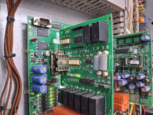
Material choice is where industrial reliability is won or lost – choosing the right industrial pcb materials is the first step to a high reliability pcb. Use this decision matrix to match the board to the stress it will see – it’s the same logic our engineers apply during DFM.
| If your board must… | Specify | Why it matters |
|---|---|---|
| Run hot / survive lead-free reflow | High-Tg FR-4 (Tg 170–180°C) | Standard FR-4 expands sharply past ~135°C; high-Tg controls Z-axis growth on plated holes. |
| Carry high current / dissipate heat | Heavy copper (3–6+ oz) | Thicker copper raises current capacity and spreads heat in power supplies and drives. |
| Move heat off LED / power devices | Aluminum substrate (IMS) | Metal core gives a low-resistance thermal path to the chassis for dissipation. |
| Hold signal integrity at speed | Controlled-impedance stackup | Defined stackup keeps timing and EMI in spec on fast control buses. |
| Resist a corrosive / humid plant | CAF-resistant laminate + conformal coating | Blocks moisture, dust and corrosive gas films per IPC-6012 reliability criteria. |
These aren’t repackaged generic PCBS, we specify, design and build these to the environment in which the control will run in – that’s the distinction between an industrial PCB and a commodity one. These design decisions go straight to cost and the lead-time which we cover in more detail under our procurement section below.
ENGINEERING INSIGHT
Industrial-Grade vs Consumer-Grade PCB, and the Honest Class 2/3 Decision
Contrary to what most suppliers imply, “industrial” does not automatically mean Class 3. The deciding factor is the consequence of failure, not the word on the datasheet. An HMI display or a temperature sensor board is fully compliant at IPC Class 2 — paying for Class 3 there is wasted money, while a safety-interlock or motor-drive board may genuinely need it.
Why get one more than we actually need? We’d rather tell you what tier you require than attempt to oversell a level of service you don’t really need – check this data to see what separates the true industrial controllerboard from commercial grade products.
Industrial-Grade vs Consumer-Grade PCB Reliability Comparison — industrial pcb vs commercial pcb, in numbers
Attribute
Consumer-grade
Industrial-control grade
Operating temperature
0 to +70°C
-40 to +85°C (high-Tg FR-4)
IPC workmanship class
Class 1–2
Class 2 or 3 (application-driven)
Inspection rigor
Sample-based
Up to 100% AOI + X-ray + flying probe
Copper weight
~1 oz
Up to heavy copper (3 oz+)
Conformal coating
Rare
Optional for moisture / corrosion / dust
Design service life
2–3 years
7–10+ years target
What actually changes between Class 2 and Class 3
Class 2
typical commercial and industrial systems, in which the failure of equipment can be, and is non-catastrophic. Common applications include HMIs, sensors, and control components for communication devices. Sample inspection and full functional testing will be employed.
Class 3
high reliability/harsh environment devices where equipment failures can and would be unacceptable (may involve safety-critical systems, if appropriate). 100% inspection and no electricals to pass through in process testing shall be in order, supported by automated methods like those in USPTO patent US 10,168,383 on testing PCB assembly. Larger annular rings and thicker board layers, in line with IPC-6012 requirements for high-reliability product.
AUDIT TRANSPARENCY
The other thing that makes our potential clients stay and do repeat business, that many competitor sites skimp over, is the ‘why’: We recommend Class along with an application map so you’ll pass a formal or informal quality or process audit – a level of transparency we build into the test as described in the next few section.
SLIDE TO REVEAL
Want a class recommendation for your operating conditions?
Request a custom comparison →PCB Solutions by Industrial Control Application
The rigors applied to a PCB are determined by its specific use – so a well-built industrial automated machinery PCB must correspond to your industrial automation hardware; Our Application-to-Specification map explains how we do that… it doubles as a useful RFQ/check-list for a design for your application.
SPEC.MAP
The Industrial Control Application to PCB Spec Map
Application
Typical board need
PCBark capability
PLC & I/O modules
Multilayer, Class 2/3, mixed SMT + THT
8 SMT lines + through-hole + functional test
Motor drives / VFD
Heavy copper, high-voltage clearance (≥6 mm at 500 V per IPC-2221)
Heavy copper + 0–50 KN press-fit connectors
Switching power supplies (SMPS)
Thermal management, high-current traces
Aluminum IMS / heavy copper for dissipation
HMI / operator panels
Fine-pitch, Class 2 sufficient
0201 & BGA placement, AOI verified
Sensors & instrumentation
Controlled impedance, conformal coating
Impedance test + coating + flying-probe test
Industrial IoT gateways
HDI / multilayer, RF sections
Multilayer build + electrical test
How We Build Reliability In, Process, Testing & Traceability
Reliability isn’t the final check on a finished PCB; it’s a chain that spans from design-for-manufacturability (DFM) to final traceability-linked testing. We offer integrated design-through-test to minimise handoffs for a smooth and efficient project from design file through fully tested, working electronic assembly. We record for you: where each part of your board was built and to what specifications.
01.
Our team runs a Design for Manufacturability and Reliability (DFM) Review on your PCB design to catch manufacturability & risk issues before you pay for tooling based on established IPC guidelines.
02.
Our facilities perform transparent procurement & PCB manufacturing: including LDI Laser Direct Imaging & CNC routing & drilling on our 5 dedicated lines; while in house Metrology Lab carries out 100% Copper peel tests, trace impedance checks and material property verifications.
03.
We assemble your through-hole components using the standard industry mix of Wave Solder processes whilst all surface-mount components (SMT) will undergo high-volume automated pick & place placement and reflow soldering followed by inline Solder Paste Inspection (SPI).
04.
Depending on the required reliability we also offer, X-Ray, and 100% functionally testing, flying probe test, AOI and In-circuit test(ICT) to support a burn-in strategy and where necessary, can provide conformal coating for your application to prevent contamination for hazardous environments.
Six test methods, in-house
The cheapest way to make a “cheap” board costly is to skip testing – a defective bare board sent to assembly is much more expensive than a clean one caught at the fabrication level. We perform in-house X-ray, AOI, ICT, flying probe, burn-in, and functional tests to identify defects and track them, rather than passing them off to a customer.
“On control boards we treat X-ray and flying-probe as non-negotiable, not optional. A hidden BGA void or a hairline open won’t show on a visual pass, it shows up six months later as a line stoppage, and by then it’s the customer’s problem, not ours.”
— PCBark Engineering Team, Process & Quality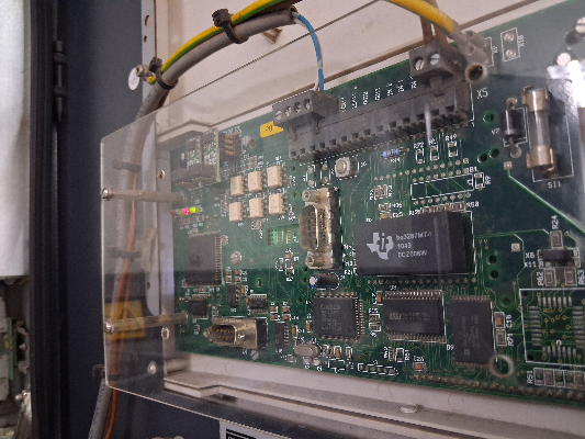
We use standard conformal coating techniques and patented chemistries for applications in corrosive or humid plants, like US 5,102,712 on the conformal coating of printed circuit boards.
Coupled with a CAF-resistant laminate, this protection prevents dendrites and salt spray corrosion and ensures durability in a corrosive environment where a less expensive vendor would skip this critical process. Because it would be more expensive for us to provide non-standard testing or not track parts, we keep the entire manufacturing and 8-line assembly process under our own roof to ensure quality control.
Request a capability walk-through →Certifications & Compliance
Our most commonly reported audit red flag involves missing Certificates of Conformity. While others produce just a logo and then “go silent” when these documents are requested, we’ve complete documentation for all claims, linked to 100% test traceability under an ISO 9001 and IATF 16949 certified system.
ISO 9001:2015
Quality management (PCB & assembly)
ISO 14001:2015
Environmental management
IATF 16949
Automotive-grade quality system
UL
Recognized board construction
CE / RoHS
EU compliance & lead-free
IPC-A-610
Assembly acceptability, Class 2/3
To satisfy an auditor, a supply chain need proof: a Certificate of Conformance, full material lot traceability, and test results tied to every production run. This trail of documentation comes standard from our 16+ year history as an IATF 16949-audited operation – not as an expensive add-on. It underlies the procurement terms detailed here.
Verified Certificates (SCROLL →)
RESOURCES / SPECIFICATIONS
Procurement Guide, MOQ, Lead Times & What Drives Cost
Buyers repeatedly cite two types of pricing deception: a low starting price that escalates with undeclared add-ons by shipment, and “optional” features included by default that drive up cost. Our quoting process reflects the clarity and integrity of our assembly and fabrication processes – no hidden charges or surprise selections.
What drives an industrial control PCBA quote
| Cost driver | How it affects price & lead time |
|---|---|
| Layer count & stack-up | More layers and controlled impedance add fabrication steps. |
| Copper weight / material | Heavy copper, high-Tg FR-4 and aluminum IMS cost more than standard FR-4. |
| IPC class (2 vs 3) | Class 3 adds 100% inspection and tighter tolerances — choose it only where failure consequence demands. |
| Test scope | ICT, flying probe and X-ray coverage scale with reliability targets (see USPTO patent US 10,048,312 on PCB assembly testing). |
| Finish & coating | ENIG, conformal coating and special finishes add process and time. |
| Volume & turn time | Prototype-to-production spans 1–15 days; quick-turn carries a premium. |
We scale quickly from prototype to high volume on our own 8-line floor, so your designs are proven for production and don’t require costly re-qualification. Two deceptions we strictly avoid: bait-and-switch pricing, and the silent adding of costly items like tented vias. Provide us with a Gerber, BOM, and Pick-N-Place files for a clear, itemized quote without forced add-ons.
Ready to scope your build?
Send your BOM for a 24-hour quote →
SYSTEM / ANALYSIS
The Field-Failure Cost of the Wrong Industrial PCB
$260,000 / hour
— industry-average cost of unplanned manufacturing downtime in 2024. At that, the premium for industrial-grade materials and full testing is paid back the very first time a board doesn’t fail.
The Field-Failure Cost Framework
A control board’s material cost is minuscule compared to the economic impact of its failure on the production line; the critical question isn’t its price, but the cost of each minute of its operation or, worse, its downtime.
The total cost of ownership on a control board is dominated by the cost of long-term reliability, not the unit price. Any board operating for years under constant industrial use will pay for itself by avoiding the only failure mode that can cause a catastrophic setback: an unscheduled downtime incident costing roughly $260,000 per hour. Unlike a broker that ships whatever a cheap PCB fab can throw together, we own the entire production process end to end – from in-house fabrication to our 8-line assembly floor – so the reliability you pay for is the reliability you get. Board-level integration of protection, as in USPTO patent US 10,594,246, is one way the industry engineers field failures out of control hardware.
-
01
Let’s specify the exact IPC class for the precise level of failure consequences – neither more, nor less.
-
02
The tests that address the failure modes your application just can’t afford to live with, the ones you pay for.
-
03
Every single detail, thoroughly documented – to transform a potential field failure into a traceable event.
Weighing industrial-grade against a cheaper quote?
Get a quote based on your volume →
SYSTEM TOOLS
Industrial PCB Engineering Tools
Access our technical utilities to configure material stack-ups, determine appropriate IPC classifications, and calculate trace current capacities for industrial control applications.
What’s a control PCB (or industrial control PCB)? It’s a printed circuit board that manages the operational logic and power distribution circuitry for a piece of automated industrial hardware, such as a Programmable Logic Controller (PLC), a variable frequency drive (VFD), or an embedded sensor. In industrial applications, it has a broader temperature tolerance, meets higher IPC classes, and undergoes more rigorous testing than typical consumer-grade circuitry.
Industrial control PCB assembly emphasizes wider temperature ranges (-40 to +85°C), higher IPC standards, heavier gauge copper traces for high current capacities, and fuller testing compared to consumer electronics production. These boards endure years of operation inside rugged industrial machinery, where reliability and complete traceability matter far more than minimizing unit costs.
Not necessarily – that’s our candid assessment. IPC class 3 is designed for applications where a board failure would result in severe consequences, such as safety interlock systems or critical motor drives. Many HMI screens, as well as certain types of sensors, perform adequately and reliably with the adherence to class 2 specifications. We consult with our customers to select the optimal class for their specific application and provide detailed justifications for our recommendations.
Our products comply with ISO 9001, IATF 16949 (for automotive applications), UL standards, CE directives, RoHS guidelines, and are assembled according to IPC-A-610 workmanship criteria. Our testing suite covers X-ray imaging, automated optical inspection (AOI), in-circuit testing (ICT), flying probe testing, burn-in, and final functional verification. Each board is accompanied by a Certificate of Conformance and complete traceability records.
High glass transition temperature (Tg) FR-4 laminates (Tg 170-180C) are used to withstand thermal stress and lead-free reflow processes, thick copper foils for managing high current and thermal dissipation, and aluminum substrates for optimal thermal management in demanding environments. The appropriate material selection is determined during our Design for Manufacturing (DFM) analysis based on the unique operational parameters of your intended application environment.
From rapid prototypes with turn times of 1 day to mass production quantities, we provide consistent quality across the full spectrum of production volumes, on a 1 to 15 day turnaround. Simply provide us with your Gerber files, Bill of Materials (BOM), and Pick-N-Place (XYRS) data, and we’ll issue an itemized quote promptly.
True reliability is built through a strong quality management system and a rigorous testing discipline, not determined by geography. Every board is backed by auditable ISO/IATF standards, an internal suite of six distinct testing methods, and complete documentation, so every claim of quality is verifiable.
![16-24 Layer PCB: Stackup, Lamination & Design Guide [2026]](https://pcbark.com/wp-content/uploads/2026/07/16-24-layer-pcb-guide-featured-2-150x150.png)


